Omnivision Module
1 Overview
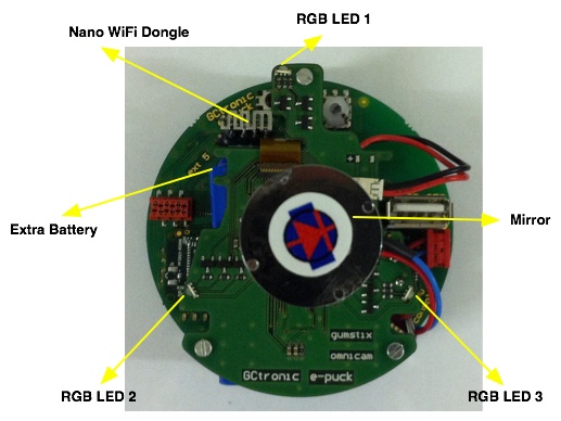
The omnivision module is an extension that is coupled with the e-puck extension for Gumstix Overo COM. The camera is the same as the one mounted on the e-puck, having a maximum resolution of 640x480 (thus 480x480 for this purpose) and a framerate of 18 fps with the current driver. The module includes the camera and 3 RGB leds as shown in the following figure.
The package will contain the omnivision extension board already mounted on the Gumstix extension (comprised of a Gumstix Earth COM) with the camera connected with the flex ribbon cable and a nano wifi dongle that is out of sight of the camera; the package is strongly recommended since the assembly is a little tricky, but the extension alone is available too for those who already have an e-puck extension for Gumstix Overo COM (nano wifi not included in this case).
The driver of the camera is open-source, you can find it in the camera driver section.
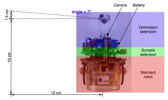
The field of view is up to 7 degrees over the horizon.
2 Getting started
2.1 1. Hardware
The camera mounted on the robot must be removed to avoid conflicts on the I2C bus.
2.2 2. Software
A specific firmware must be charged on the e-puck when working with this extension, it can be downloaded from section E-Puck#Standard_firmware. Remember to put the selector in position 10.
The system on the micro sd is the same used for the gumstix extension alone, refer to section https://www.gctronic.com/doc/index.php/Overo_Extension#File_system_image for more informations.
2.3 3. Terminal configuration
Execute a terminal program (e.g. minicom) and configure the connection with 115200-8N1. The serial device path should be typically something like "/dev/ttyUSB0". Make sure that the flow control parameter of minicom called "Hardware" is set to "No".
2.4 4. U-Boot
In order to use the extension module it's required to modify the boot commands within u-boot, as shown afterwards:
- 1) Turn on the robot and enter the u-boot command line by pressing "any key" when the following message is shown (it is displayed in a few seconds after turning on the robot):
Hit any key to stop autoboot: 1
- 2) modify the variable mmcargs, this will activate the clock for the camera:
setenv mmcargs setenv bootargs console=${console} video=${videospec},mode:${videomode} root=/dev/mmcblk0p2 rw
rootfstype=ext3 rootwait po6030cam.omap_gen_clock=1
- 3) add a new environment variable called confleds:
setenv confleds "mw.w 0x480020CE 0x000C; mw.w 0x48002114 0x000C; mw.w 0x48002126 0x000C; mw.w 0x48002128 0x000C;
mw.w 0x4800212A 0x000C; mw.w 0x4800212C 0x000C; mw.w 0x4800212E 0x000C; mw.w 0x48002132 0x000C; mw.w 0x48002130 0x000C"
- 4) modify the bootcmd varibale in order to call confleds:
setenv bootcmd "run confleds; if mmc init; then if run loadbootscript; then run bootscript; else if run loaduimage;
then run mmcboot; else run nandboot; fi; fi; else run nandboot; fi"
- 5) save the environment variables in order to preserve the configuration for the next boots:
saveenv
reset
- 6) login with user=root, password=root
2.5 5. WiFi
The nano WiFi dongle shipped with the extension board is an Edimax EW-7811Un, based on a Realtek chipset (RTL8192cu). The device isn't recognized automatically at boot, so you need to follow these steps in order to enable and use it:
- turn on the robot and login with user=root, password=root
- type insmod 8192cu.ko (the kernel module is located in /home/root); the wifi dongle should be recognized and a wlanX device created
- type ifconfig wlanX up (where X is a number) to turn on the device; now the wifi can be configured and used normally
2.6 6. Demos
Once logged in it's possible to execute the demos:
- type ./demos/test-leds to run the basic leds test demo
- type ./demos/leds-pwm to run the pwm demo
For more information and source code refer to Software section
3 Software
3.1 Demos
All the demos using the camera proposed in the gumstix extension section will work also with the omnivision module. Moreover some specific demos for this extension are available in the next sections.
3.1.1 Basic leds test demo
This application is thought to illustrate how to communicate with the 3 RGB leds of the omnivision extension. Basically there are 9 gpio lines (one for each color) exported automatically in the system (see section Getting started) that can be used to turn on and off all the leds. For more information on gpio refer to the section GPIO - pins mode. The leds test demo can downloaded from the following link test-leds.c.
3.1.2 PWM demo
This demo handles the leds implementing a software pwm; this let the user have finer control on the leds, that is their brightness is controllable and the range of reproducible colors is greater acting on the duty cycle of each one of the RGB leds. Once the application is started the user can control the duty cycles through the console with the following commands:
- red led 1: q (inc duty), w (dec duty)
- green led 1: a (inc duty), s (dec duty)
- blue led 1: y (ind duty), x (dec duty)
- red led 2: e (inc duty), r (dec duty)
- green led 2: d (inc duty), f (dec duty)
- blue led 2: c (inc duty), v (dec duty)
- red led 3: t (inc duty), z (dec duty)
- green led 3: g (inc duty), h (dec duty)
- blue led 3: b (inc duty), n (dec duty)
The leds handled through pwm demo can downloaded from the following link leds-pwm.c.
3.2 Camera driver
Refer to section camera driver for more information about the driver of the e-puck camera.
4 Image unwrapping
Once you get an image from the camera you can post-process the image in order to see the whole 360-degrees laid out in a rectangular strip. For this purpose vision software called RoboRealm; you can download a free 30 days trial.
Once you installed the software you can proceed with the following steps:
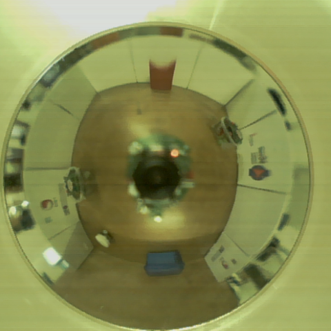
1) Grab an image from the camera:
2) Start RoboRealm, open the grabbed image and apply a polar transformation (Transforms=>Polar); you should get an image similar to the following one:
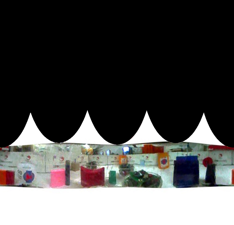
3) Finally you need to simply cut the relevant part of the image, as shown here:
5 Omnivision module with Caspa camera board
This version of the omnivision module use the caspa camera board instead of using the e-puck camera. It's based on the 2.6.34 kernel so it isn't possible to use both the robot camera and the omnivision camera, since at the moment the driver of the e-puck camera isn't compatible with the 2.6.34 kernel. Moreover the RGB leds aren't usable with this omnivision hardware version (not connected).
An image can be grabbed with the following command; in the example the image is cropped to 480x480 starting at offset (136,0) and saved as jpeg (10 frames grabbed):
mplayer tv:// -vo jpeg -vf crop=480:480:136:0 -ss 1 -frames 10 -loop 1 -tv driver=v4l2:device=/dev/video0
If the image results too dark, especially in indoor enviornments, it is possible to enable a camera parameter (companding) when loading the driver; follow these steps:
# rmmod mt9v032
# insmod /lib/modules/2.6.34/kernel/drivers/media/video/mt9v032.ko low_light=1
Now the next grabbed images should be brighter.
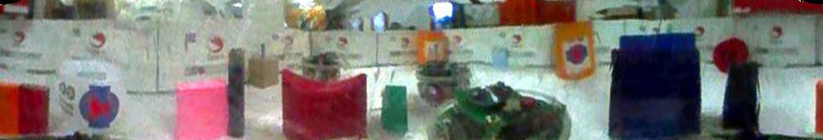
In order to setup the wifi connection, you need first stop "NetworkManager" with the following command:
/etc/init.d/NetworkManager stop
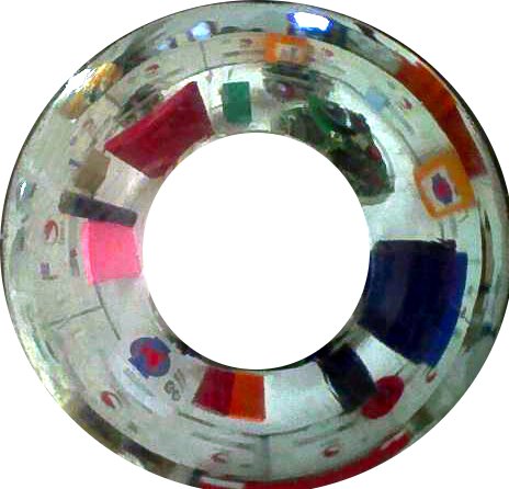
The following image is grabbed with the omnivsion coupled with the caspa: