e-puck2 programmer development
Flashing the programmer
First of all to update the programmer's firmware you need to enter DFU mode (device firmware upgrade). To do it refer to section Using the DFU, in particular Note 2.
The programmer will be recognized as STM Device in DFU Mode device.
Linux
In order to update the programmer firmware you need an utility called dfu-util.
To install it issue the command sudo apt-get install dfu-util.
Then issue the following command to upload the firmware: sudo dfu-util -d 0483:df11 -a 0 -s 0x08000000 -D programmer-firmware.bin
Windows
For Windows users it is available an application called DfuSe released by STMicroelectronics. You can download it from DfuSe_V3.0.5.zip.
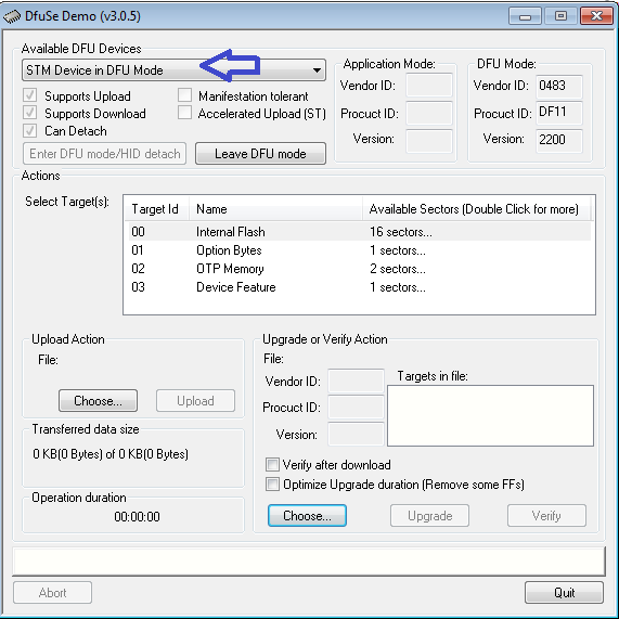
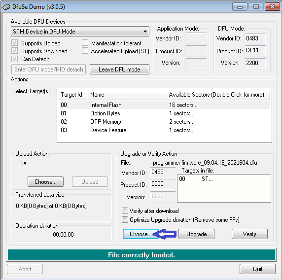
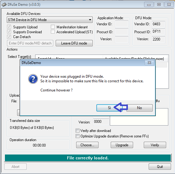
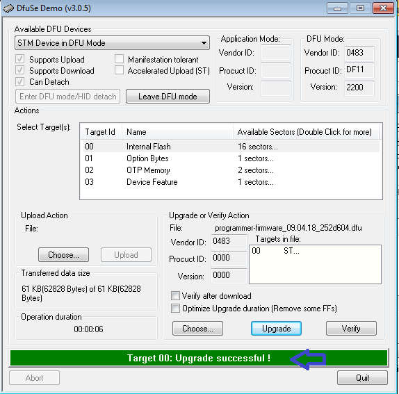
When the program is started, the programmer in DFU mode will be automatically detected as shown in figure 1. Then you need to open the compiled firmware by clicking on choose and then locating the file, as shown in figure 2. Now click on the upgrade button, a warning message will be shown, confirm the action by clicking on yes as shown in figure 3. If all is ok you'll be prompted with a message saying that the upgrade was successfull as shown in figure 4.
| [1] | [2] | [3] | [4] |
 |
 |
 |
 |
Configuring the Programmer's settings
The on-board programmer of the e-puck2 is based on the Blackmagic probe open source project firmware.
Some functionalities has been added on top of the original project to be able to control some functions of the robot, for example the power on or power off.
To access to the available commands of the programmer, it is needed to connect to the programmer with a GDB console.
To do so, you have to type the following command in a terminal window with the com port used by the 'e-puck2 GDB Server port of your e-puck2 :
arm-none-eabi-gdb
target extended-remote your_gdb_com_port
Once connected to the programmer with GDB, you can type
monitor help
or
mon help
to print the available commands of the programmer.
One command in particular is useful, which is mon select_mode. It is used to select in which mode the e-puck2 Serial Monitor com port will work.
mode 1 = the serial monitor is connected to the UART port of the main processor
mode 2 = the serial monitor is connected to the UART of the ESP32
mode 3 = the serial monitor works as a Aseba CAN to USB translator
The choice made for the mode is the only setting that is stored in a flash zone of the programmer, which means the choice is remembered, even if the robot is completely turned off.
Note : in mode 1 and 3, GDB can be used over the bluetooth connection of the e-puck2. But is is much slower than with USB and it doesn't work with Windows due to GDB limitations on this OS.
By being connected with GDB, you can also use the standard GDB command to program and debug the main processor of the e-puck2.
Using the DFU
To put the e-puck2 into DFU, it is needed to turn it on while keeping pressed the "407 boot" button located under the electronic card on the left side of the robot.
The robot will appear as "STM32 BOOTLOADER" in the USB devices.
Once in DFU, you can program it with dfu-util using the following command :
dfu-util -d 0483:df11 -a 0 -s 0x08000000 -D your_firmware.bin
See the manual page of dfu-util for further information on how to use it.
Note: For windows, it is needed to install a libusbK driver for the DFU device.
You can use the Zadig program located in the Eclipse_e-puck2\Tools\ (if you installed Eclipse_e-puck2 package) to install it.
Follow the same procedure as explained above under the Installation drivers section using libusbK driver instead of USB Serial (CDC).
Note 2: It is also possible to put the programmer in DFU by contacting two pinholes together while inserting the USB cable (no need to turn on the robot).
It is used to update the firmware of the programmer.
The two pin holes are located near the USB connector of the e-puck2, see the photo below.
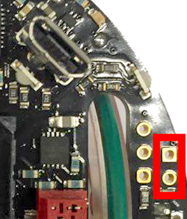
- Location of the pin holes to put the programmer into DFU