Pi-puck: Difference between revisions
| Line 72: | Line 72: | ||
==Audio recording== | ==Audio recording== | ||
Use the <code>arecord</code> utility to record audio from the onboard | Use the <code>arecord</code> utility to record audio from the onboard microphone. The following example shows how to record an audio of 2 seconds (<code>-d</code> parameter) and save it to a wav file (<code>test.wav</code>):<br/> | ||
<code>arecord -Dmic_mono -c1 -r16000 -fS32_LE -twav -d2 test.wav</code><br/> | <code>arecord -Dmic_mono -c1 -r16000 -fS32_LE -twav -d2 test.wav</code><br/> | ||
You can also specify a rate of 48 KHz with <code>-r48000</code> | You can also specify a rate of 48 KHz with <code>-r48000</code> | ||
Revision as of 05:52, 22 May 2019
Overview
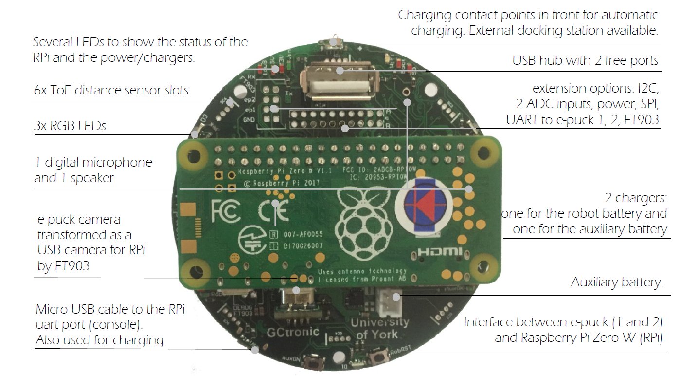
Features:
- Raspberry Pi zero W (rPi) connected to the robot via I2C
- interface between the robot base camera and the rPi via USB
- 1 digital microphone and 1 speaker
- USB hub connected to the rPi with 2 free ports
- uUSB cable to the rPi uart port. Also ok for charging
- 2 chargers. 1 for the robot battery and 1 for the auxiliary battery on top of the extension
- charging contact points in front for automatic charging. External docking station available
- several extension options. 6 i2C channels, 2 ADC inputs
- several LED to show the status of the rPi and the power/chargers
Getting started
This introductory section explains the minimal procedures needed to work with the Raspberry Pi Zero W mounted on the Pi-puck extension board and gives a general overview of the available basic demos and scripts shipped with the system flashed on the micro SD. More advanced demos are described in the following separate sections (e.g. ROS), but the steps documented here are fundamental, so be sure to fully understand them.
The extension is mostly an interface between the e-puck robot and the Raspberry Pi, so you can exploit the computational power of a Linux machine to extend the robot capabilities.
In most cases, the Pi-puck extension will be attached to the robot, but it's interesting to note that it can be used also alone when the interaction with the robot isn't required.
The following sections assume the full configuration (robot + extension), unless otherwise stated.
Requirements
The robot must be programmed with a special firmware in order to communicate via I2C bus with the Raspberry Pi mounted on the Pi-puck extension. The same I2C bus is shared by all the devices (camera, IMU, distance sensor, others extensions), the main microcontroller and the Raspberry Pi. Since the Raspberry Pi acts as I2C master, these devices will not be anymore reachable directly from the robot main microcontroller that will act instead as I2C slave.
e-puck1
e-puck2
The e-puck2 robot must be programmed with the following firmware e-puck2_main-processor_gumstix.elf (13.12.18) and the selector must be placed in position 10.
Turn on/off the extension
To turn on the extension you need to press the auxON button as shown in the follwoing figure; this will turn on also the robot (if not already turned on):
Similarly, if you turn on the robot then also the extension will turn on automatically.
To turn off the robot you need to press and hold the auxON button for 2 seconds; this will initiate the power down procedure.
/
Beware that if you turn off the robot, then the extension will remain turned on.
Console mode
The Pi-puck extension board comes with a pre-configured system ready to run without any additional configuration.
In order to access the system from a PC in console mode, the following steps must be performed:
1. connect a micro USB cable from the PC to the extension module. If needed, the drivers are available in the following link USB to UART bridge drivers
2. execute a terminal program and configure the connection with 115200-8N1 (no flow control). The serial device is the one created when the extension is connected to the computer
3. switch on the robot (the extension will turn on automatically); now the terminal should display the Raspberry Pi booting information. If the robot isn't present, then you can directly power on the extension board with the related button
4. login with user = pi, password = raspberry
Demos and scripts update
First of all you should update to the last version of the demos and scripts released with the system that you can use to start playing with the Pi-puck extension and the robot.
To update the repository follow these steps:
1. go to the directory /home/pi/Pi-puck
2. issue the command git pull
You can find the Pi-puck repository here https://github.com/gctronic/Pi-puck.
Communicate with the robot
An example showing how to exchange data between the robot and the Pi-puck extension is available in the Pi-puck repository; you can find it in the directory /home/pi/Pi-puck/e-puck2/.
You can build the program with the command gcc e-puck2_test.c -o e-puck2_test.
Now you can run the program by issueing ./e-puck2_test; this demo will print the sensors data on the terminal and send some commands to the robot at 2 Hz.
Communicate with the IMU
An example showing how to read data from the IMU is available in the Pi-puck repository; you can find it in the directory /home/pi/Pi-puck/e-puck2/.
You can build the program with the command gcc e-puck2_imu.c -o e-puck2_imu.
Now you can run the program by issueing ./e-puck2_imu and then choose whether to get data from the accelerometer or gyroscope; this demo will print the sensors data on the terminal.
Communicate with the ToF sensor
Capture an image
The robot camera is connected to the Pi-puck extension as a USB camera, so you can access it very easily.
An example showing how to capture an image from the robot's camera using OpenCV is available in the Pi-puck repository; you can find it in the directory /home/pi/Pi-puck/snapshot/.
You can build the program with the command g++ $(pkg-config --libs --cflags opencv) -ljpeg -o snapshot snapshot.cpp.
Now you can run the program by issueing ./snapshot; this will save a VGA image (JPEG) named image01.jpg to disk.
The program can accept up to 2 parameters: the first parameter specifies how many images to capture (1-99) and the second parameter specifies whether to print debug information (1) or not (0). Beware that in this demo the acquisition rate is fixed to 5 Hz, but the camera supports up to 15 FPS.
Audio recording
Use the arecord utility to record audio from the onboard microphone. The following example shows how to record an audio of 2 seconds (-d parameter) and save it to a wav file (test.wav):
arecord -Dmic_mono -c1 -r16000 -fS32_LE -twav -d2 test.wav
You can also specify a rate of 48 KHz with -r48000
Audio play
Use aplay to play wav files and mplayer to play mp3 files.
Battery reading
An example showing how to measure both the battery of the robot and the battery of the Pi-puck extension is available in the Pi-puck repository; you can find it in the directory /home/pi/Pi-puck/battery/.
The first time you need to change the mode of the script in order to be executable with the command sudo chmod +x read-battery.sh.
Then you can start reading the batteries value by issueing ./read-battery.sh.; this demo will print the batteries values (given in Volts) on the terminal.
WiFi configuration
Specify your network configuration in the file /etc/wpa_supplicant/wpa_supplicant-wlan0.conf.
Example:
ctrl_interface=DIR=/var/run/wpa_supplicant GROUP=netdev
update_config=1
country=CH
network={
        ssid="MySSID"
        psk="9h74as3xWfjd"
}
You can have more than one network parameter to support more networks.
File transfer
Image streaming
Operating system
The system is based on Raspbian Stretch and can be downloaded from the following link gctronic-stretch-ros-kinetic-opencv3.4.1.img.tar.gz.
When booting the first time, the first thing to do is expanding the file system in order to use all the available space on the micro sd:
1. sudo raspi-config
2. Select Advanced Options and then Expand Filesystem
3. reboot
Desktop mode
The system starts in console mode, to switch to desktop (LXDE) mode issue the command startx.
Camera viewer
ROS
ROS Kinetic is integrated in the Pi-puck system.
Initial configuration
The ROS workspace is located in ~/rosbots_catkin_ws/
The e-puck2 ROS driver is located in ~/rosbots_catkin_ws/src/epuck_driver_cpp/
Remember to follow the steps in the section Requirements , only once.
Remember to follow the steps in the section System: Startup configuration, each time the system is powered on.
The PC (if used) and the Pi-puck extension are supposed to be configured in the same network.
Running roscore
roscore can be launched either from the PC or directly from the Pi-puck.
Before starting roscore, open a terminal and issue the following commands:
export ROS_IP=roscore-ipexport ROS_MASTER_URI=http://roscore-ip:11311
where roscore-ip is the IP of the machine that runs roscore
Then start roscore by issueing roscore.
Running the ROS node
Before starting the e-puck2 ROS node on the Pi-puck, issue the following commands:
export ROS_IP=pipuck-ipexport ROS_MASTER_URI=http://roscore-ip:11311
where pipuck-ip is the IP of the Pi-puck extension and roscore-ip is the IP of the machine that runs roscore (can be the same IP if roscore runs directly on the Pi-puck).
To start the e-puck2 ROS node issue the command:
roslaunch epuck_driver_cpp epuck_minimal.launch debug_en:=true ros_rate:=20
The following graph shows all the topics published by the e-puck2 driver node:
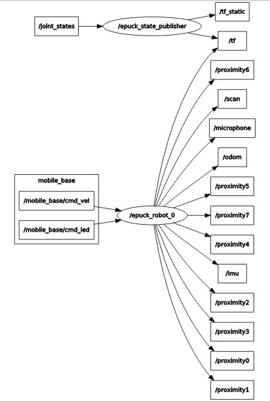 Click to enlarge
Get the source code
The last version of the e-puck2 ROS node can be downloaded from the git: git clone -b e-puck2 https://github.com/gctronic/epuck_driver_cpp.git
OpenCV
OpenCV 3.4.1 is integrated in the Pi-puck system.