Others Extensions: Difference between revisions
(Created page with "=Range and bearing= <span class="plainlinks">[http://www.gctronic.com/doc/images/randb-1-small.jpg <img height=150 src="http://www.gctronic.com/doc/images/randb-1.jpg">][http:...") |
(No difference)
|
Revision as of 08:48, 28 February 2018
1 Range and bearing
The board allows situated agents to communicate locally, obtaining at the same time both the range and the bearing of the emitter without the need of any centralized control or any external reference. Therefore, the board allows the robots to have an embodied, decentralized and scalable communication system. The system relies on infrared communications with frequency modulation and is composed of two interconnected modules for data and power measurement.
You can find more information about this board in the following links: http://www.e-puck.org/index.php?option=com_content&view=article&id=35&Itemid=23, http://www.rbzrobotdesign.com/en/products/e-puck.
A simple MPLAB project was created to let start using these modules. With the selector it's possible to choose whether the robot is an emitter (selector in position 0) or a receiver (selector in position 1). The receiver will send the information (data, bearing, distance, sensor) through Bluetooth.
2 Ground sensors

You can find more information about the ground sensors extension module in the following link http://www.e-puck.org/index.php?option=com_content&view=article&id=17&Itemid=18.
The main demo was extended to handle the ground sensors extension for the e-puck, this demo can be found in this link http://projects.gctronic.com/E-Puck/DemoGCtronic-complete-groundsensor/DemoGCtronic-complete-groundsensor.hex. In order to get the values from the sensors you must put the selector in position 3 and then issue the command m that will return three values, one for each sensor.
If you are interested in the sources you can refer to the section http://www.gctronic.com/doc/index.php/E-Puck#Standard_firmware in which there is a link to the MPLAB project and some information on how to build it; to enable the ground sensors you need to uncomment the definition at the top of the Asercom.c file before building.
If you couple the e-puck extension for Gumstix Overo with the ground sensor refer to the section http://www.gctronic.com/doc/index.php/Overo_Extension#Ground_sensor to have an example on how to read the sensor values.
3 Cliff sensor
The cliff module extends the capability of the groundsensor with two additional sensors placed in front of the wheels. One possible application is that the e-puck can now detect the end of a table and react accordingly. Moreover this module can be coupled with the automatic charger for the e-puck, that could let the robot autonomously charge itself when needed. The two spring contacts adapt only to the cliff module.
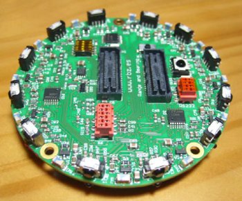
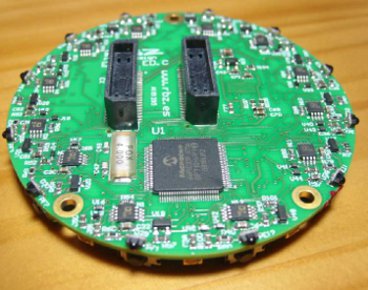
3.1 Assembly
| [1] | [2] | [3] | [4.1] | [4.2] |
 |  |  |  |  |
| [5.1] | [5.2] | [6] | [7] | [8] |
 | 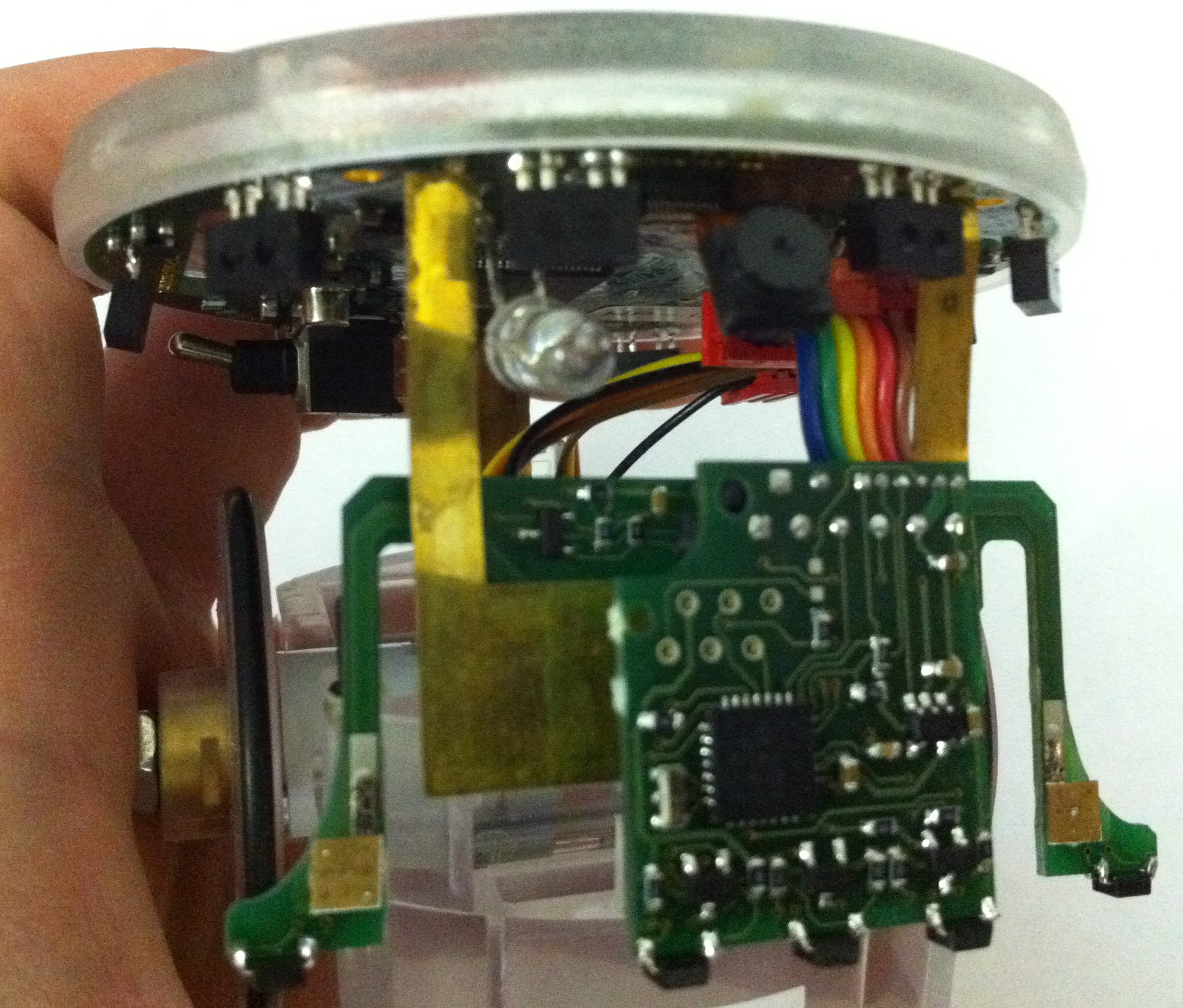 | 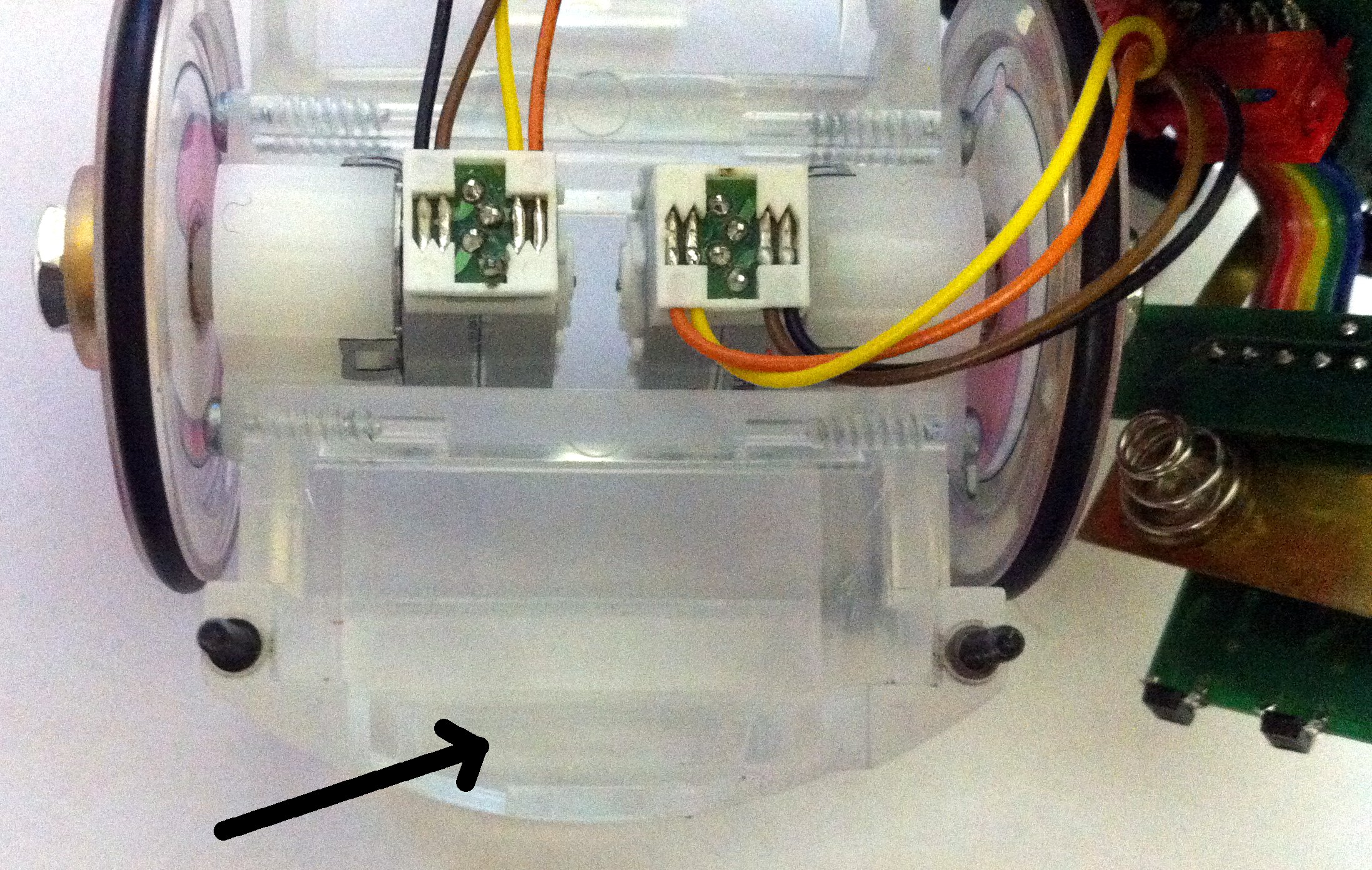 | 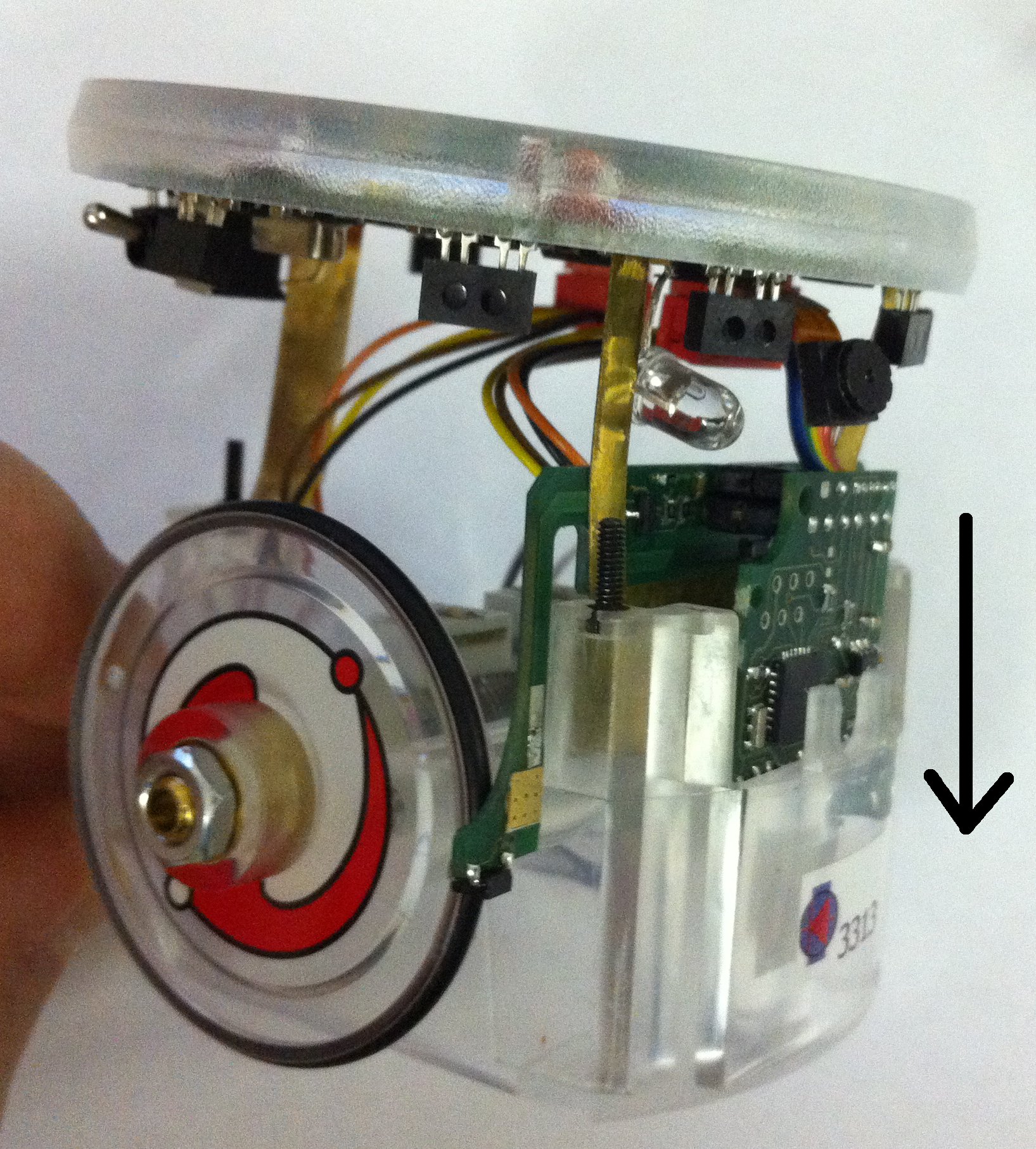 |  |
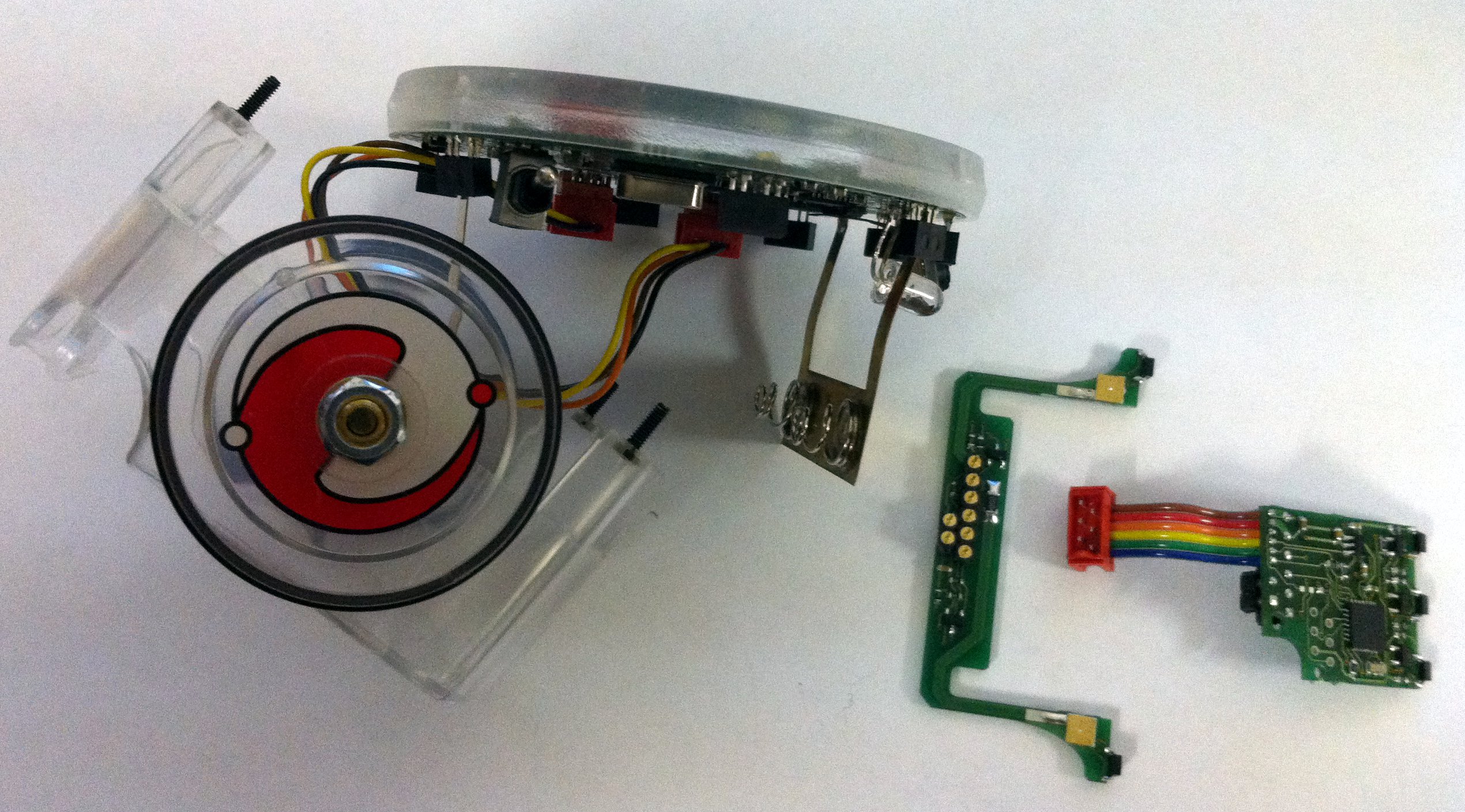
- Unscrew the 3 screws, unmount the e-jumper (top piece where there is the speaker) and unscrew the 3 spacers
- Remove the pcb from the case body gently
- Detach the two parts, cliff and ground pcb
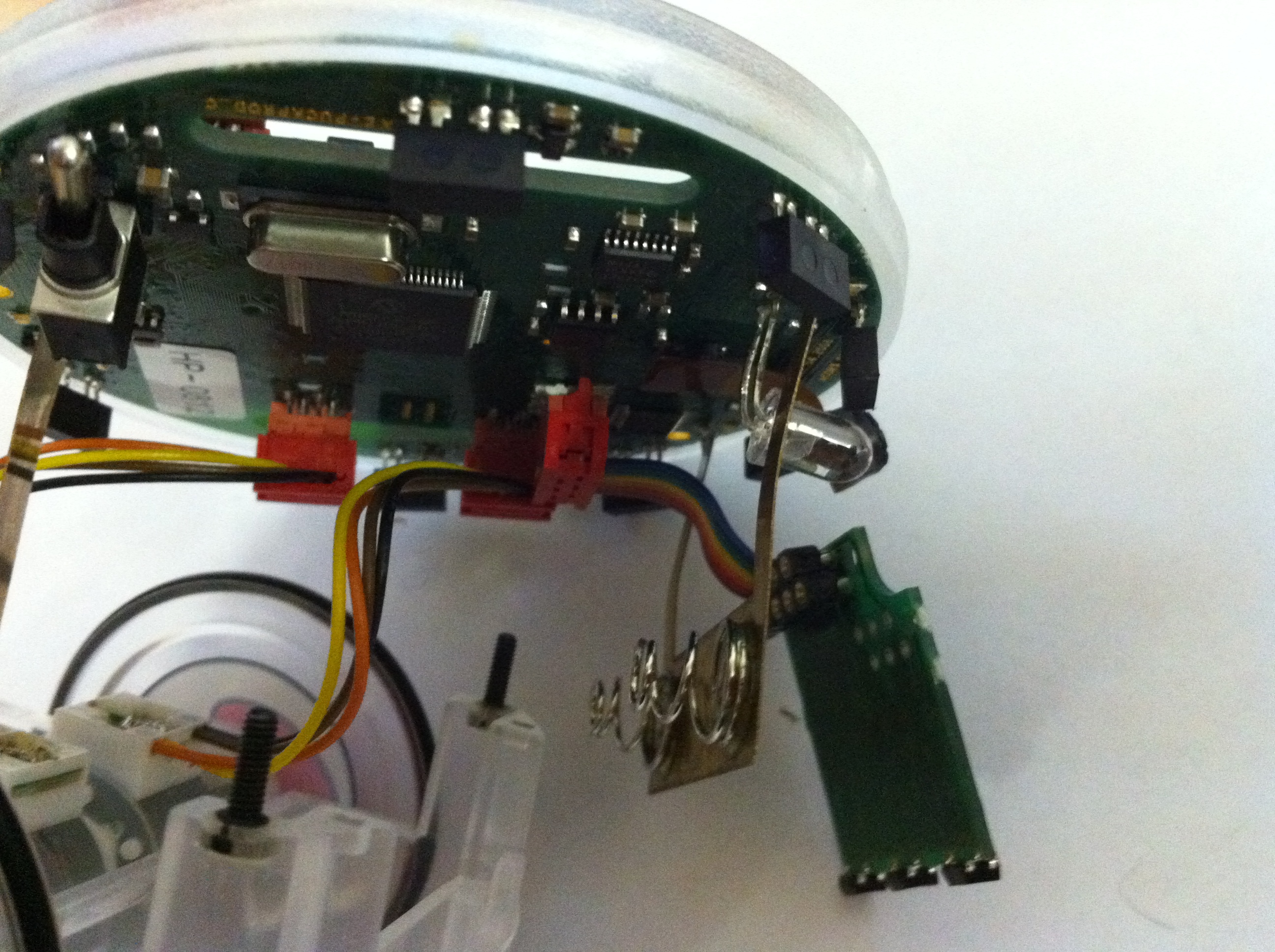
- Plug the ground module into its connector on the e-puck
- Attach the cliff module to the ground module being careful to leave the battery contact in the middle
- Push the ground module within its slot in the body case, the cliff module will remain external
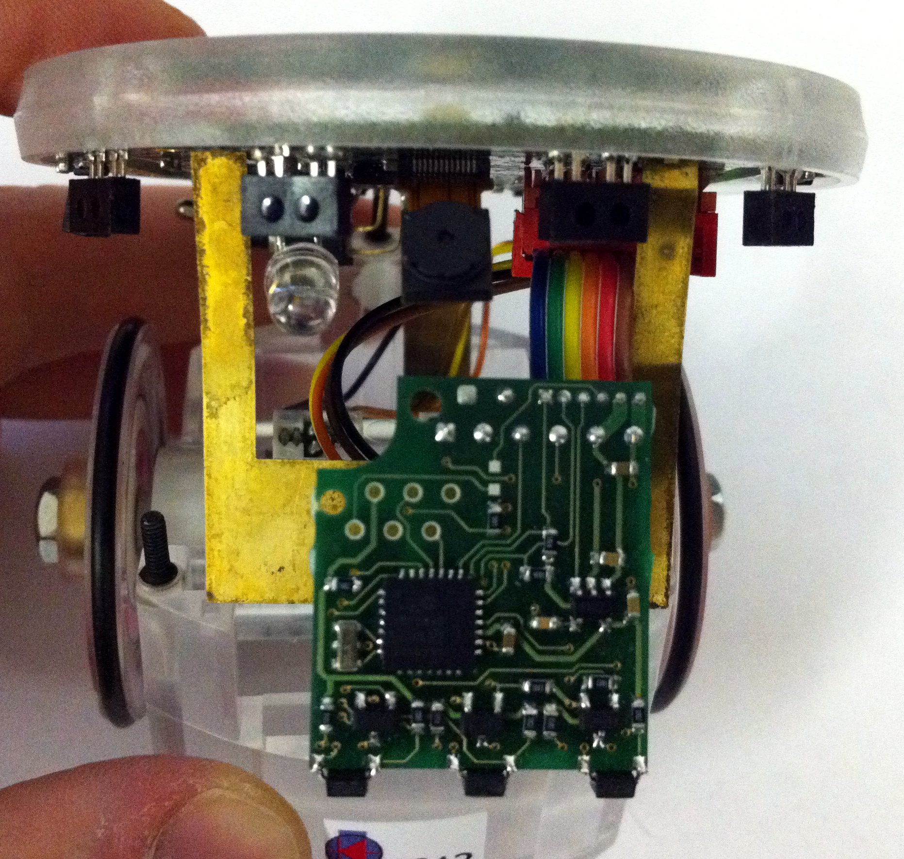
- Once both the modules are aligned, push them down
- The modules will remain really close to the case bottom; once the modules are fitted remount the spacers, the e-jumper and the screws
3.2 Electrical schema
The circuit diagram of the e-puck cliff extension is available to the community on the following link electrical schema.
3.3 Software
3.3.1 e-puck firmware
Refers to the section E-Puck Standard firmware for the firmware that need to be uploaded to the robot. Essentially the standard asercom demo (selector 3) released with the e-puck robot is extended in order to request and visualize 5 sensors values instead of 3 when issueing the m command; the sequence is: ground left, ground center, ground right, cliff right, cliff left. In order to enable the cliff sensors you need to define CLIFF_SENSORS in the asercom.c file in order to build the code parts related to this module.
3.3.2 e-puck demos
To demonstrate the capabilities of the cliff sensors module here is an MPLAB project Demo-cliff-autocharge.zip that contains two demos:
- selector 0: in this demo the robot is eventually piloted to the charger station autonomously after moving around for some time aovoiding obstacles; the demo is shown in the video section.
- selector 1: this is a cliff avoidance demo in which the robot is moved forward until it detects the end of the table and tries to avoid it moving back and rotating; the demo is shown in the video section.
3.3.3 Extension firmware
The ground sensor fimrware developed at EPFL (can be downloaded at the http://www.e-puck.org site from this page) was extended to interact with the additional two sensors. The source code can be downloaded from cliff-firmware; it is an MPLAB project and the MPLAB C Compiler for PIC18 MCUs is needed to build the project.
The communication between the e-puck and the module is handled through I2C (address 0xC0) and the following registers are defined:
- 0x00: reflected light, left IR sensor - high byte
- 0x01: reflected light, left IR sensor - low byte
- 0x02: reflected light, center IR sensor - high byte
- 0x03: reflected light, center IR sensor - low byte
- 0x04: reflected light, right IR sensor - high byte
- 0x05: reflected light, right IR sensor - low byte
- 0x06: ambient light, left IR sensor - high byte
- 0x07: ambient light, left IR sensor - low byte
- 0x08: ambient light, center IR sensor - high byte
- 0x09: ambient light, center IR sensor - low byte
- 0x0A: ambient light, right IR sensor - high byte
- 0x0B: ambient light, right IR sensor - low byte
- 0x0C: software revision number
- 0x0D: reflected light, right cliff sensor - high byte
- 0x0E: reflected light, right cliff sensor - low byte
- 0x0F: reflected light, left cliff sensor - high byte
- 0x10: reflected light, left cliff sensor - low byte
- 0x11: ambient light, right cliff sensor - high byte
- 0x12: ambient light, right cliff sensor - low byte
- 0x13: ambient light, left cliff sensor - high byte
- 0x14: ambient light, left cliff sensor - low byte
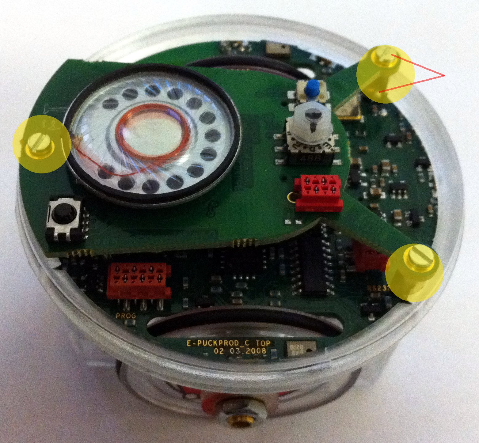
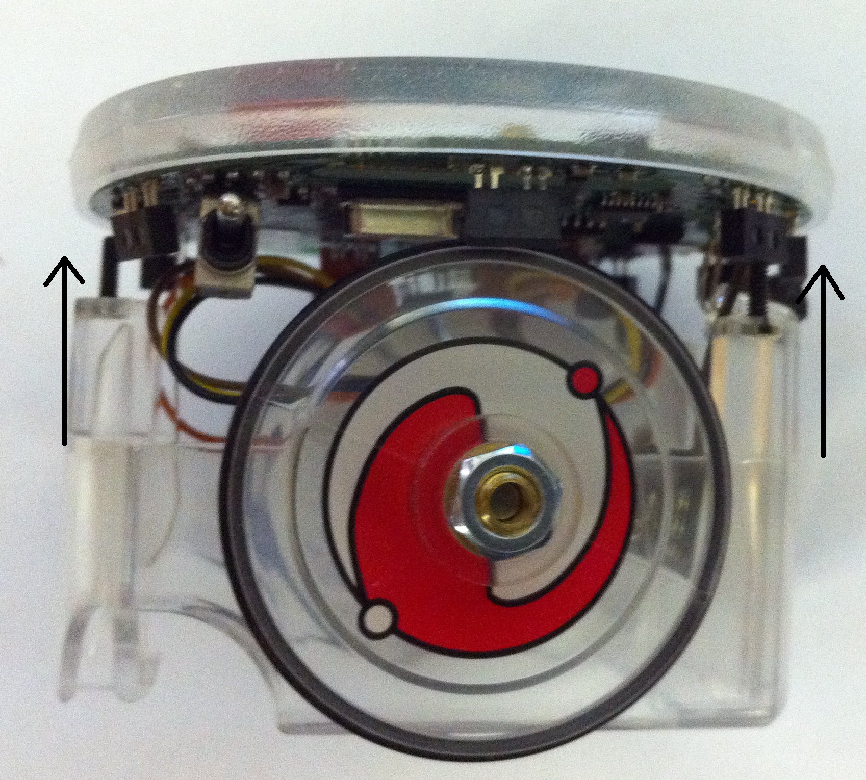
3.4 Images
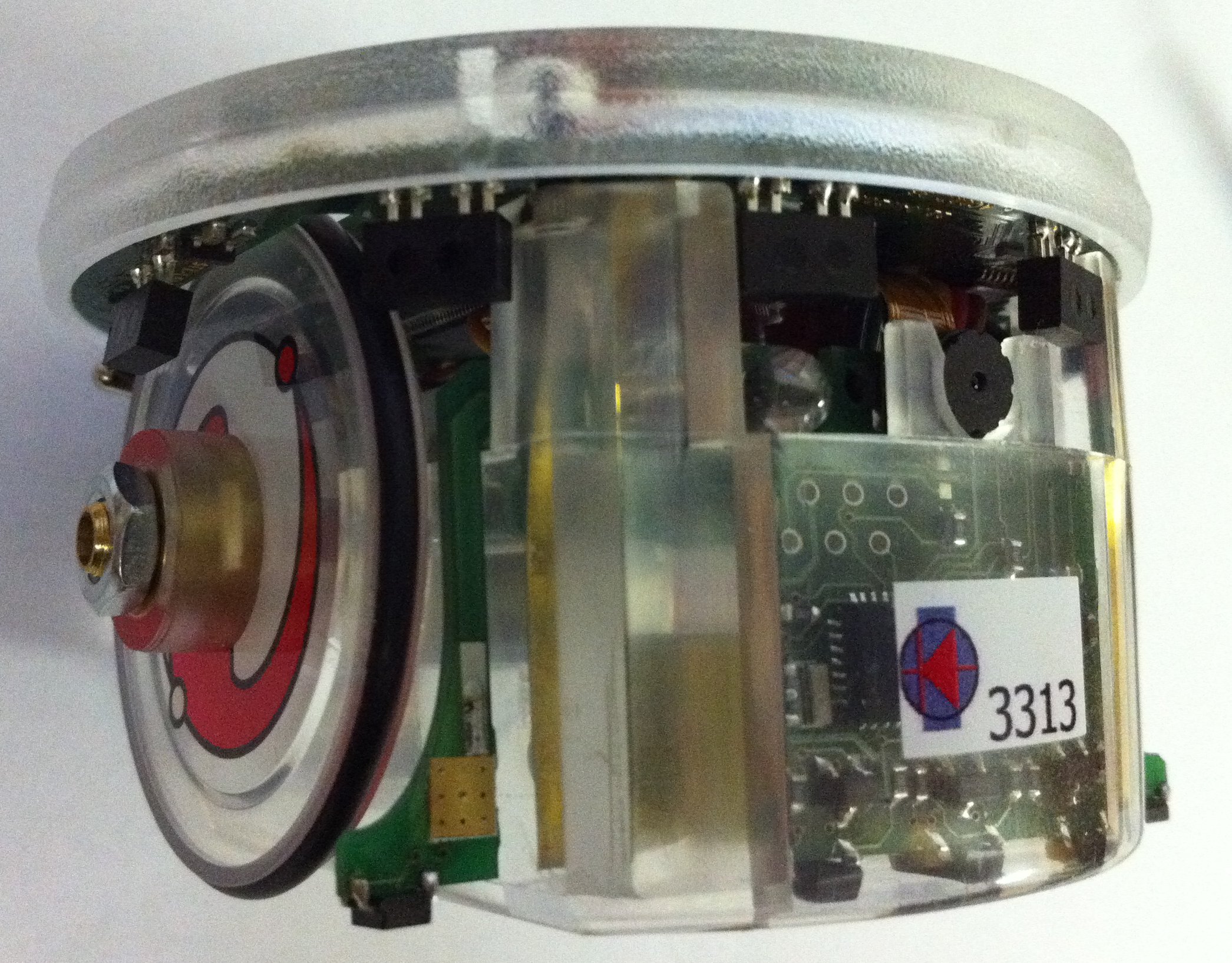
Robot equipped with the cliff sensor:
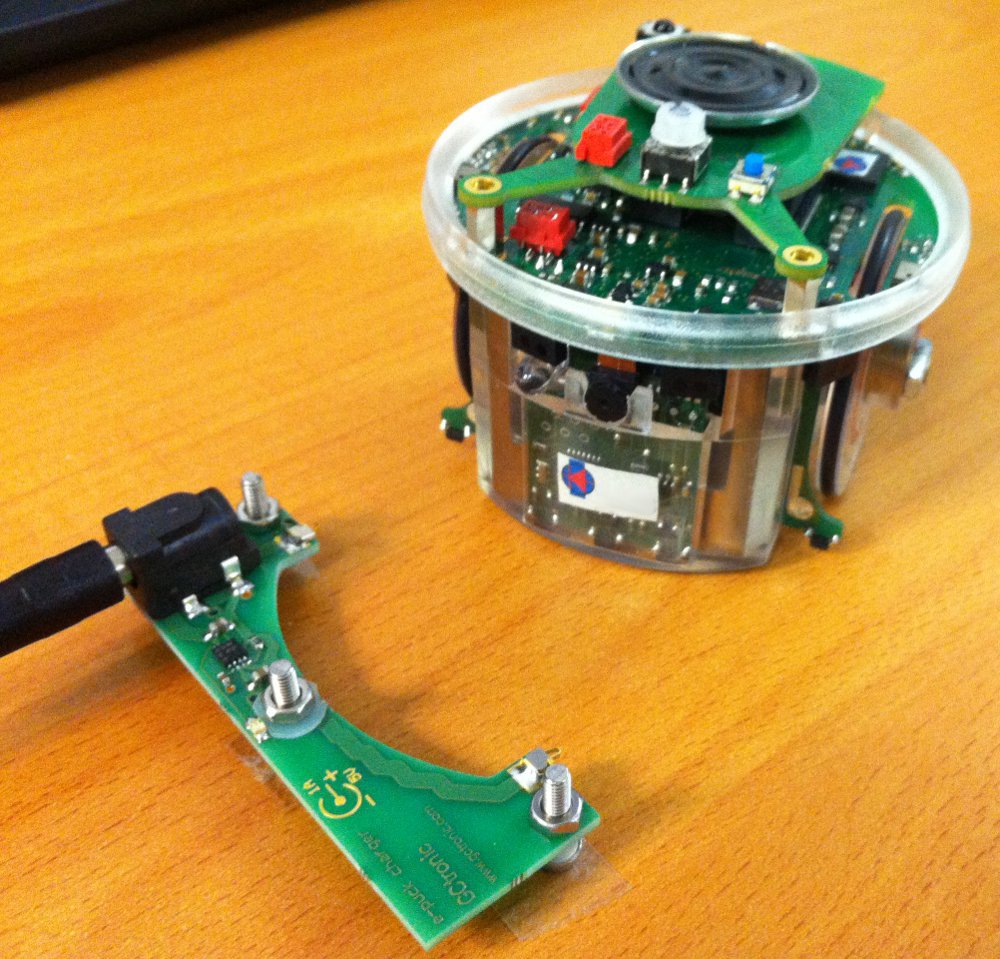
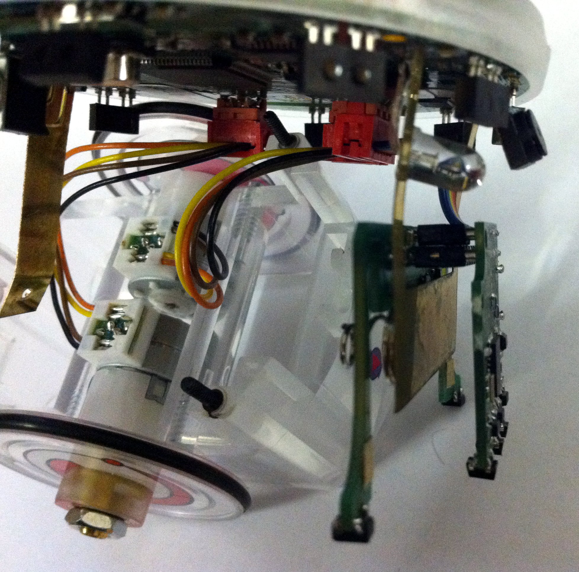
The robot can be easily moved to the charging station as shown in the following figure:
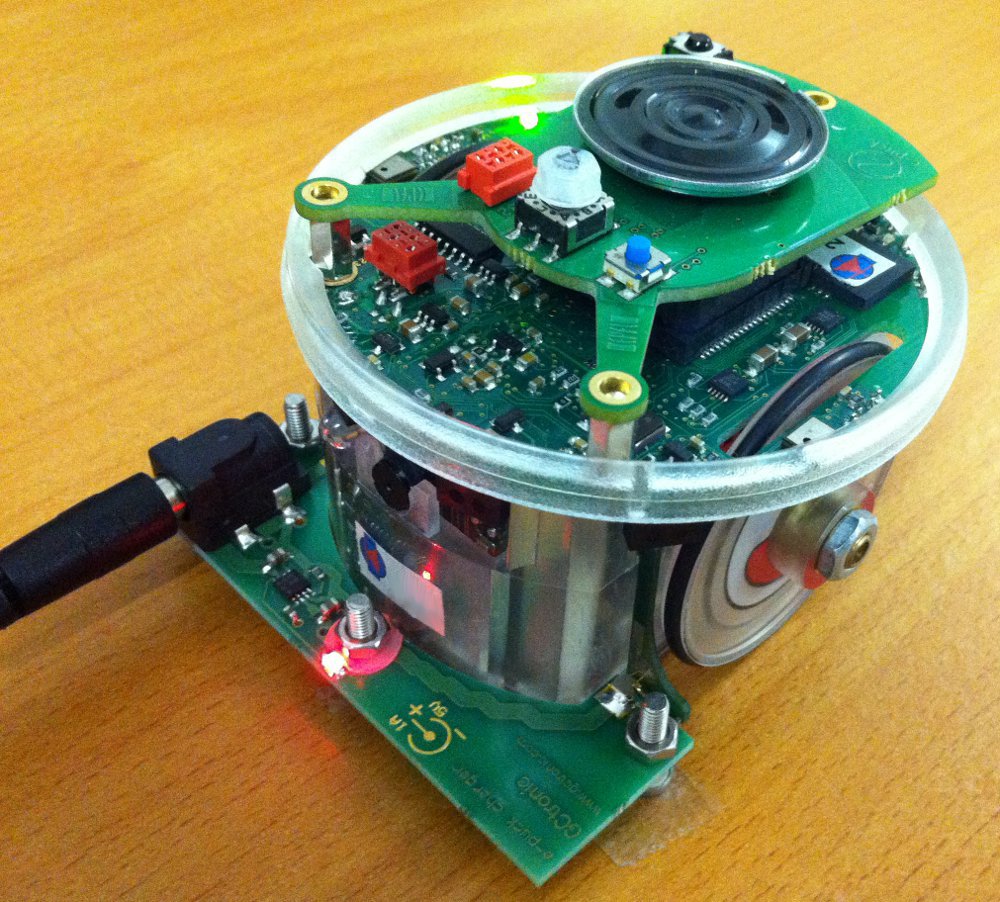
The following figure shows the two additional sensors (near the wheels) mounted on the cliff module and the three frontal sensors of the ground module:
