e-puck2 PC side development
Robot firmware update
Now and then there could be an official firmware update for the robot and it's important to keep the robot updated with the last firmware to get possibile new features, improvements and for bug fixes.
The onboard programmer run a GDB server, so we use GDB commands to upload a new firmware, for this reason a toolchain is needed to upload a new firmware to the robot.
The following steps explain how to update the robot firmware:
1. Download the package containing the required toolchain and script to program the robot: Windows, [Linux], [Mac OS]
2. Download the last version of the robot standard firmware
3. Extract the package and put the firmware file (with elf extension) inside the package directory; beware that only one elf file must be present inside this directory
4. Attach the USB cable and turn on the robot
5. Run the script:
- Windows: double click
program.bat - Linux:
- Mac OS:
Robot configuration
This section explains how to configure the robot based on the communication channel you will use for your developments, thus you need to read only one of the following sections, but it would be better if you spend a bit of time reading them all in order to have a full understanding of the available configurations.
Bluetooth and USB
The robot is initially programmed with a firmware that includes many demos that could be started based on the selector position, refer to section Standard firmware for a list of all the demos and related description.
If the robot isn't programmed with the standard firmware or if you want to be sure to have the last firmware on the robot, you need to program it with the last standard firmware, refer to section Robot firmware update.
When you want to interact with the robot from the computer you need to place the selector in position 3 if you want to work with Bluetooth, or in position 8 if you want to work with USB. Both communication channels use the same protocol called asercom v2, refer to section Communication protocol: BT and USB for detailed information about this protocol.
WiFi
For working with the WiFi there is a special firmware, refer to section [].
Communication protocol
Bluetooth and USB
WiFi
The communication is based on TCP; the robot create a TCP server and wait for a connection.
Each packet is identified by an ID (1 byte). The following IDs are used to send data from the robot to the computer:
- 0x00 = reserved
- 0x01 = QQVGA color image packet (only the first segment includes this id); packet size (without id) = 38400 bytes; image format = RGB565
- 0x02 = sensors packet; packet size (without id) = 104 bytes; the format of the returned values are based on the asercom protocol and are compatible with e-puck1.x:

- Acc: raw axes values, between -1500 and 1500, resolution is +-2g
- Acceleration: acceleration magnitude
 , between 0.0 and about 2600.0 (~3.46 g)
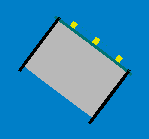
 - Orientation: between 0.0 and 360.0 degrees
0.0 deg 90.0 deg 180 deg 270 deg 


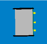
- Inclination: between 0.0 and 90.0 degrees (when tilted in any direction)
0.0 deg 90.0 deg 
- Gyro: raw axes values, between -32768 and 32767, range is +-250dps
- Magnetometer: raw axes values, between -32760 and 32760, range is +-4912 uT (magnetic flux density expressed in micro Tesla)
- Temp: temperature given in Celsius degrees
- IR proximity: between 0 (no objects detected) and 4095 (object near the sensor)
- IR ambient: between 0 (strong light) and 4095 (dark)
- ToF distance: distance given in millimeters
- Mic volume: between 0 and 4095
- Motors steps: 1000 steps per wheel revolution
- Battery:
- uSD state: 1 if the micro sd is present and can be read/write, 0 otherwise
- TV remote data: RC5 protocol
- Selector position: between 0 and 15
- Ground proximity: between 0 (no surface at all or not reflective surface e.g. black) and 1023 (very reflective surface e.g. white)
- Ground ambient: between 0 (strong light) and 1023 (dark)
- Button state: 1 button pressed, 0 button released
- Inclination: between 0.0 and 90.0 degrees (when tilted in any direction)
- 0x03 = empty packet (only id is sent); this is used as an acknowledgment for the commands packet when no sensors and no image is requested
The following IDs are used to send data from the computer to the robot:
- 0x80 = commands packet; packet size (without id) = 20 bytes:
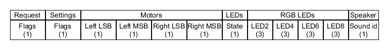
- request:
- bit0: 0=stop image stream; 1=start image stream
- bit1: 0=stop sensors stream; 1=start sensors stream
- settings:
- bit0: 1=calibrate IR proximity sensors
- bit1: 0=disable onboard obstacle avoidance; 1=enable onboard obstacle avoidance (not implemented yet)
- bit2: 0=set motors speed; 1=set motors steps (position)
- left and right: when bit2 of
settingsfield is0, then this is the desired motors speed (-1000..1000); when1then this is the value that will be set as motors position (steps) - LEDs: 0=off; 1=on; 2=toggle
- bit0: 0=LED1 off; 1=LED1 on
- bit1: 0=LED3 off; 1=LED3 on
- bit2: 0=LED5 off; 1=LED5 on
- bit3: 0=LED7 off; 1=LED7 on
- bit4: 0=body LED off; 1=body LED on
- bit5: 0=front LED off; 1=front LED on
- RGB LEDs: for each LED, it is specified in sequence the value of red, green and blue (0...100)
- sound id: 0x01=MARIO, 0x02=UNDERWOLRD, 0x04=STARWARS, 0x08=4KHz, 0x10=10KHz, 0x20=stop sound
- request:
For example to receive the camera image (stream) the following steps need to be followed:
1) connect to the robot through TCP
2) send the command packet:
0x80 0x01 0x00 0x00 0x00 0x00 0x00 0x00 0x00 0x00 0x00 0x00 0x00 0x00 0x00 0x00 0x00 0x00 0x00 0x00 0x00
3) read the ID (1 byte) and the QQVGA color image pakcet (38400 bytes)
4) go to step 3
Webots
TBD
ROS
TBD