e-puck2
Hardware
Overview
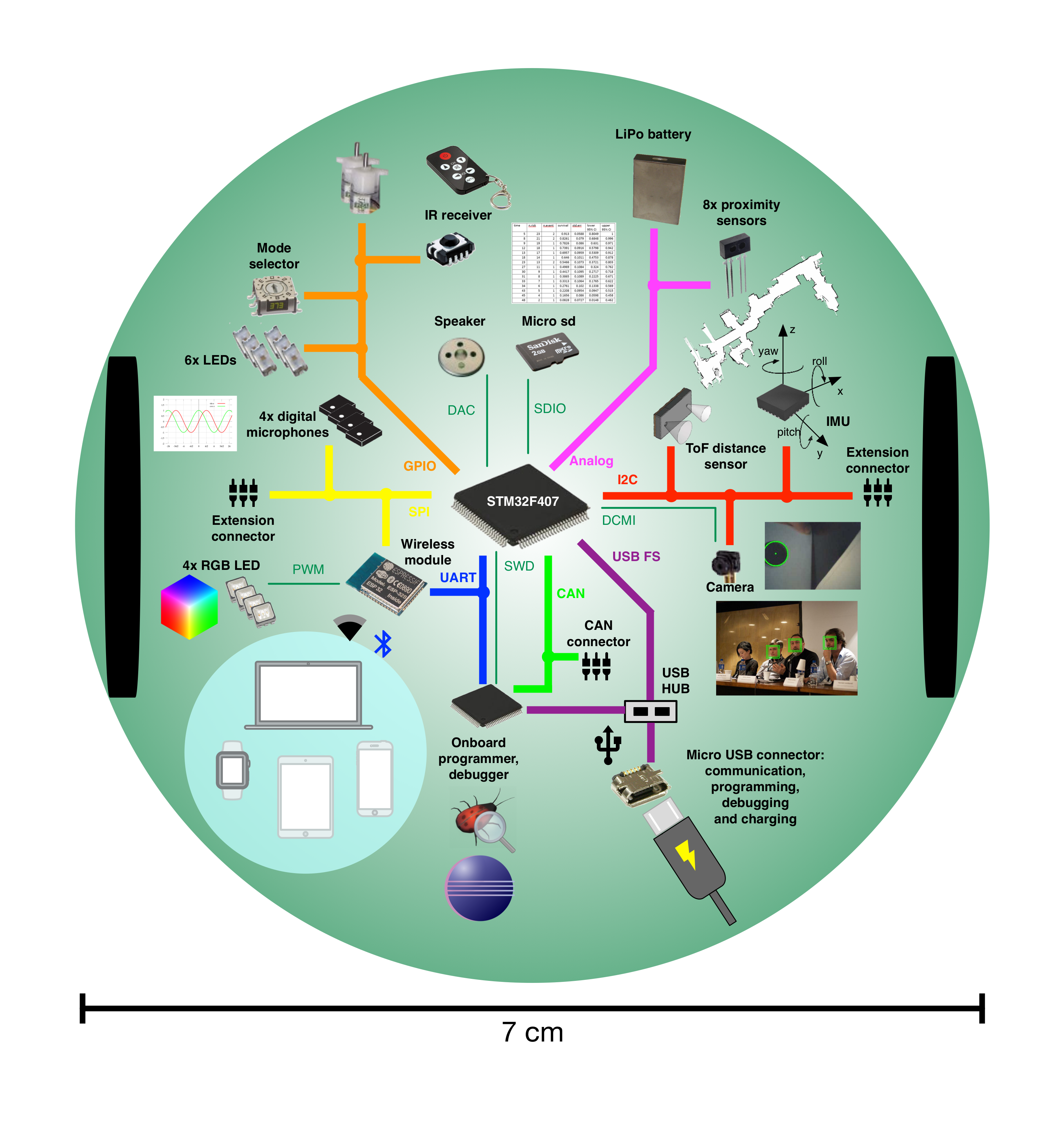
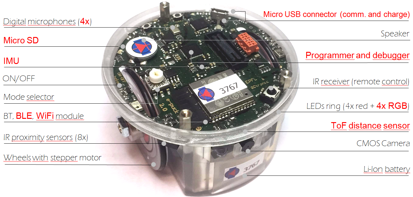
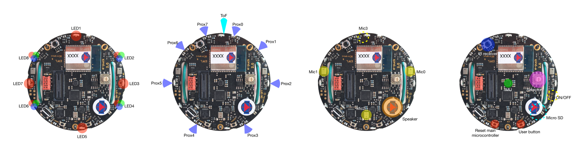
The following figures show the main components offered by the e-puck2 robot and where they are physically placed:
Specifications
The e-puck2 robot maintains full compatibility with its predecessor e-puck (e-puck HWRev 1.3 is considered in the following table):
| Feature | e-puck1.3 | e-puck2 | Compatibility | Additional |
| Size, weight | 70 mm diameter, 55 mm height, 150 g | Same form factor: 70 mm diameter, 45 mm, 130 g | No e-jumper required | |
| Battery, autonomy | LiIPo rechargeable battery (external charger), 1800 mAh. About 3 hours autonomy. Recharging time about 2-3h. |
Same battery; USB charging, recharging time about 2.5h. | USB charging | |
| Processor | 16-bit dsPIC30F6014A @ 60MHz (15 MIPS), DSP core for signal processing | 32-bit STM32F407 @ 168 MHz (210 DMIPS), DSP and FPU, DMA | ~10 times faster | |
| Memory | RAM: 8 KB; Flash: 144 KB | RAM: 192 KB; Flash: 1024 KB | RAM: 24x more capable Flash:~7x more capable | |
| Motors | 2 stepper motors with a 50:1 reduction gear; 20 steps per revolution; about 0.13 mm resolution | Same motors | ||
| Wheels | Wheels diamater = 41 mm Distance between wheels = 53 mm |
Same wheels | ||
| Speed | Max: 1000 steps/s (about 12.9 cm/s) | Max: 1200 steps/s (about 15.4 cm/s) | 20% faster | |
| Mechanical structure | Transparent plastic body supporting PCBs, battery and motors | Same mechanics | ||
| Distance sensor | 8 infra-red sensors measuring ambient light and proximity of objects up to 6 cm | Same infra-red sensors Front real distance sensor, Time of fight (ToF), up to 2 meter. |
ToF sensor | |
| IMU | 3D accelerometer and 3D gyro | 3D accelerometer, 3D gyro, 3D magnetometer | 3D magnetometer | |
| Camera | VGA color camera; typical use: 52x39 or 480x1 | Same camera; typical use: 160x120 | Bigger images handling | |
| Audio | 3 omni-directional microphones for sound localization speaker capable of playing WAV or tone sounds |
4 omni-directional microhpones (digital) for sound localization speaker capable of playing WAV or tone sounds |
+1 front microphone | |
| LEDs | 8 red LEDs around the robot, green body light, 1 strong red LED in front | 4 red LEDs and 4 RGB LEDs around the robot, green light, 1 strong red LED in front | 4x RGB LEDs | |
| Communication | RS232 and Bluetooth 2.0 for connection and programming | USB Full-speed, Bluetooth 2.0, BLE, WiFi | WiFi, BLE | |
| Storage | Not available | Micro SD slot | Micro SD | |
| Remote Control | Infra-red receiver for standard remote control commands | Same receiver | ||
| Switch / selector | 16 position rotating switch | Same selector | ||
| Extensions | Ground sensors, range and bearing, RGB panel, Gumstix extension, omnivision, your own | All extension supported | ||
| Programming | Free C compiler and IDE, Webots simulator, external debugger | Free C compiler and IDE, Webots simulator, onboard debugger (GDB) | Onboard debugger |
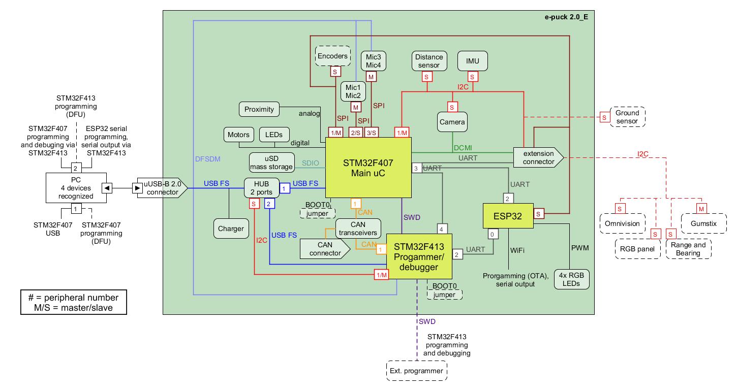
This is the overall communication schema:
Documentation
- Main microcontroller: STM32F407, datasheet, reference-manual
- Programmer/debugger: STM32F413, datasheet, reference-manual
- Radio module: Espressif ESP32, datasheet, reference-manual
- Camera: PixelPlus PO8030D CMOS image sensor, datasheet, no IR cut filter
- Microphones: STM-MP45DT02, datasheet
- Optical sensors: Vishay Semiconductors Reflective Optical Sensor, datasheet
- ToF distance sensor: STM-VL53L0X, datasheet, user-manual
- IMU: InvenSense MPU-9250, product-specification, register-map
- Motors: details
- Speaker: Diameter 13mm, power 500mW, 8 Ohm, DS-1389 or PSR12N08AK or similar
- IR receiver: TSOP36230
Installation of the e-puck2 environment
Some programs are needed to program the e-puck2.
- Eclipse_e-puck2 is a distribution of Eclipse IDE for C/C++ Developers specially modified to edit and compile e-puck2's projects out of the box. It doesn't require to be installed and everything needed is located in the package given. The only dependency needed to be able to run Eclipse is Java.
- Drivers must also be installed for Windows older than Windows 10.
Installation for Windows
Java 8 32bits
This section can be ignored if Java version 8 32bits is already installed on your computer.
To verify, you can open the Programs and Features panel and search for a Java 8 Update xxx install.
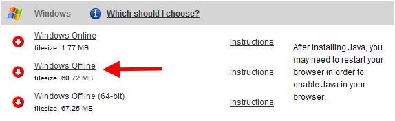
- Go to the Java download page and download "Windows offline" This is the 32bits version of Java.
- Run the downloaded installer and follow its instructions to proceed with the installation of Java 32bits.
- Close the internet browser if it opened at the end of the installation.
- Java download page
Eclipse_e-puck2
- Download the Eclipse_e-puck2 package for windows.
- Unzip the downloaded file to the location you want (can take time). It is strongly recommended for better performance and less extraction time to use 7Zip. You can download it on http://www.7-zip.org.
- You can now run the
Eclipse_e-puck2.exeto launch Eclipse. - You can create a shortcut to Eclipse_e-puck2.exe and place it anywhere if you want.
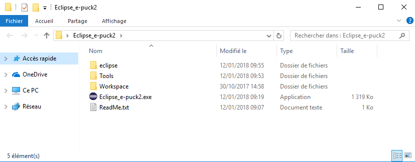
- Eclipse_e-puck2 folder obtained after extraction
Important things to avoid :
- 1. The path to the Eclipse_e-puck2 folder must contain zero space.
- Example :
C:\epfl_stuff\Eclipse_e-puck2OKC:\epfl stuff\Eclipse_e-puck2NOT OK
- 2. You must not put Ellipse_e-puck2 folder into Program Files (x86). Otherwise the compilation when using Eclipse will not work.
- 3. The file’s structure in the Eclipse_e-puck2 folder must remain the same. It means no file inside this folder must be moved to another place.
Drivers
This part concerns only the users of a Windows version older than Windows 10. The drivers are automatically installed with Windows 10.
- Open
zadig-2.3.exelocated in theEclipse_e-puck2\Tools\folder you installed before. - Connect the e-puck2 with the USB cable and turn it on. Three unknown devices appear in the device list of the program, namely e-puck2 STM32F407, e-puck2 GDB Server (Interface 0) and e-puck2 Serial Monitor (Interface 2).
- For each of the three devices mentioned above, select the
USB Serial (CDC)driver and click on theInstall Driverbutton to install it. Accept the different prompts which may appear during the process. After that you can simply quit the program and the drivers are installed. These steps are illustrated on Figure 3 below.
- Note : The drivers installed are located in
C:\Users\"your_user_name"\usb_driver
- Note : The drivers installed are located in
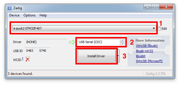
- Example of driver installation for e-puck2 STM32F407
Installation for Linux
Java 8
This section can be ignored if Java is already installed on your computer.
To verify whether it is installed or not you can type the following command into a terminal window:
update-java-alternatives -l
If Java is installed, you will get some information about it, otherwise the command will be unknown.
You need to have Java 1.8.xxxx listed to be able to run Eclipse_e-puck2.
Type the following commands in a terminal session to install Java SDK:
sudo add-apt-repository ppa:openjdk-r/ppa
sudo apt-get update
sudo apt-get install openjdk-8-jre
Eclipse_e-puck2
- Install
make(probably you already have it installed) by issueing the command:sudo apt-get install make - Download the Eclipse_e-puck2 package for Linux 32bits / 64bits. Pay attention to the 32bits or 64bits version. If unsure which Linux version you have, enter the following comand
uname -ain the terminal window and look for i686 (32bit) or x86_64 (64 bit). - Extract the downloaded file to the location you want (can take time).
- You can now run the
Eclipse_e-puck2executable to launch Eclipse.
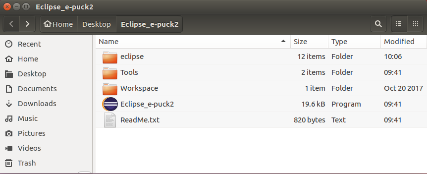
- Eclipse_e-puck2 folder obtained after extraction
Note : The icon of the Eclipse_e-puck2 executable will appear after the first launch of the program.
Important things to avoid :
- 1. You cannot create a Link to the Eclipse_e-puck2 executable because otherwise the program will think its location is where the Link is and it will not find the resource located in the Eclipse_e-puck2 folder.
- 2. The path to the Eclipse_e-puck2 folder must contain zero space.
- Example :
/home/student/epfl_stuff/Eclipse_e-puck2OK/home/student/epfl stuff/Eclipse_e-puck2NOT OK
- 3. The file’s structure in the Eclipse_e-puck2 folder must remain the same. It means no file inside this folder must be moved to another place.
Serial Port
In order to let Eclipse (or any program ran by you) to access the serial ports, a little configuration is needed.
Type the following command in a terminal session. Once done, you need to log off to let the change take effect.
sudo adduser $USER dialout
Installation for Mac
Command Line Tools
To compile on Mac with Eclipse_e-puck2, it is necessary to have the Command Line Tools installed. It is a bundle of many commonly used tools.
You can install it by typing the following command in a terminal window. It will then open a popup asking you if you want to install this bundle. Otherwise it will tell you it is already installed.
xcode-select --install
Java 8
This section can be ignored if Java is already installed on your computer.
To verify whether it is installed or not you can type the following command into a terminal window. It will list all the Java runtimes installed on your Mac.
/usr/libexec/java_home -V
You need to have Java SE 8 listed to be able to run Eclipse_e-puck2.
- 1. Go to the Java download page and download the
Mac OS X Java 8 SE Development Kit. It is the .dmg file without the Demos and Samples.- For example:
jdk-8uXXX-macosx-x64.dmg
- For example:
- 2. Open the .dmg file downloaded, run the installer and follow the instructions to proceed with the installation of Java SDK.
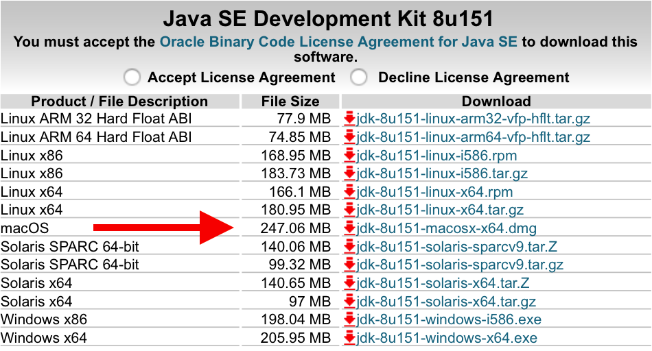
- Java download page
Eclipse_e-puck2
- 1. Download the Eclipse_e-puck2 package for Mac.
- 2. Open the .dmg file downloaded and DragAndDrop the Eclipse_e-puck2.app into the Applications folder
- Note : You can place the Eclipse_e-puck2.app anywhere, as long as the full path to it doesn’t contain any space, if you don’t want it to be in Applications.
- 3. You can create an Alias to Eclipse_e-puck2.app and place it anywhere if you want.
First launch and Gatekeeper
It’s very likely that Gatekeeper (one of the protections of Mac OS) will prevent you to launch Eclipse_e-puck2.app because it isn’t signed from a known developer.
If you can’t run the program because of a warning of the system, press OK and try to launch it by right clicking on it and choosing open in the contextual menu (may be slow to open the first time).
If Unable to open "Eclipse_e-puck2.app" because this app comes from an unidentified developer. or if "Eclipse.app" is corrupted and cannot be opened. You should place this item in the Trash. appears after executing the app the first time, it is needed to disable temporarily Gatekeeper.
To do so :
- 1. Go to
System Preferences->security and privacy->Generaland authorize downloaded application fromAnywhere.
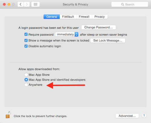
- Security settings of Mac OS
- If you are on Mac OS Sierra or greater (greater or equal to Mac OS 10.12), you must type the following command on the terminal to make the option above appear.
sudo spctl --master-disable
- 2. Now you can try to run the application and it should work.
- 3. If Eclipse opened successfully, it is time to reactivate Gatekeeper. Simply set back the setting of Gatekeeper.
- For the ones who needed to type a command to disable Gatekeeper, here is the command to reactivate it.
sudo spctl --master-enable
This procedure is only needed the first time. After that Gatekeeper will remember your choice to let run this application and will not bother you anymore, as long as you use this application. If you re-download it, you will have to redo the procedure for Gatekeeper.
Important things to avoid :
- 1. The path to the Eclipse_e-puck2.app must contain zero space.
- Example :
/home/student/epfl_stuff/Eclipse_e-puck2OK/home/student/epfl stuff/Eclipse_e-puck2NOT OK
- 2. The file’s structure in the Eclipse_e-puck2.app must remain the same. It means no file inside this app must be moved to another place.
Getting Started
Meaning of the LEDs
The e-puck2 has three groups of LEDs that are not controllable by the user.
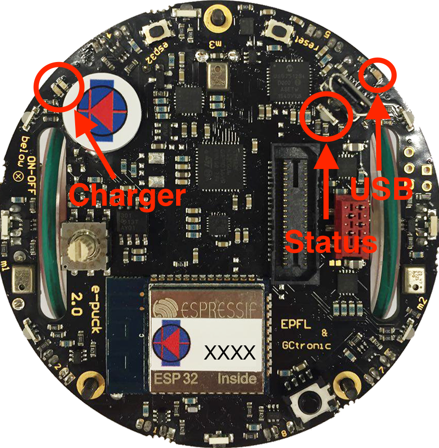
- Top view of the e-puck2
- Charger : RED if charging, GREEN if charge complete and RED and GREEN if an error occurs
- USB : Turned ON if the e-puck2 detects a USB connection with a computer
- STATUS : Turned ON if the robot is ON and OFF is the robot is OFF. When ON, gives an indication of the level of the battery. Also blinks GREEN if the program is running during a debug session.
Battery level indications (STATUS RGB LED):
- GREEN if the system's tension is greater than 3.5V
- ORANGE if the system's tension is between 3.5V and 3.4V
- RED if the system's tension is between 3.4V and 3.3V
- RED blinking if the system's tension is below 3.3V
The robot is automatically turned OFF if the system's tension gets below 3.2V during 10 seconds.
Finding the USB serial ports used
Two ports are created by the e-puck2's programmer when the USB cable is connected to the robot (even if the robot is turned off):
- e-puck2 GDB Server. The port used to program and debug the e-puck2 with Eclipse_e-puck2 (GDB).
- e-puck2 Serial Monitor. A serial monitor. #see dedicated chapter(not yet ready)
A third port could be available depending on the code inside the e-puck2's microcontroller. With the standard firmware a port named e-puck2 STM32F407 is created.
Windows
- Open the Device Manager
- Under Ports (COM & LPT) you can see the virtual ports connected to your computer.
- Do a Right-click -> properties on the COM port you want to identify.
- Go under the details tab and select Bus reported device description in the properties list.
- The name of the port should be written in the text box below.
- Once you found the desired device, you can simply look at its port number (COMX).
Linux
- 1. Open a terminal window (ctrl+alt+t) and enter the following command.
ls /dev/ttyACM*
- 2. Look for ttyACM0 and ttyACM1 in the generated list, which are respectively e-puck2 GDB Server and e-puck2 Serial Monitor.
Note : Virtual serial port numbering on Linux is made by the connections order, thus it can be different if another device using virtual serial ports is already connected to your computer.
Mac
- 1. Open a terminal window and enter the following command.
ls /dev/cu.usbmodem*
- 2. Look for two cu.usbmodemXXXX, where XXXX is the number attributed by your computer. You should find two names, more or less following in the numbering, which are respectively e-puck2 GDB Server and e-puck2 Serial Monitor.
Note : Virtual serial port numbering on Mac depends on the physical USB port used and the device. If you want to keep the same names, you must connect to the same USB port each time.
Configuring the Debugger's settings
Eclipse_e-puck2 contains everything needed to compile, program and debug the e-puck2.
The only settings to configure with a new project are located under the Debug Configurations tab of Eclipse (you can also find it on Run->Debug Configurations).
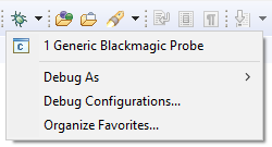
Once in the settings, select Generic Blackmagic Probe preset on the left panel. Then you need to configure two things :
- If you already have a project, under the main tab, you need to select which project to debug and the path to the compiled file. If the project has already been compiled, Eclipse must have indexed the binaries and you can list the project and the compiled files using respectively the Browse... and Search Project... buttons. If you do not already have a project, add a random name as the title which will act as a place holder, allowing you to apply the next configuration.
- Under the Startup tab, you need to replace the path to the serial port written on the first line of the text box by the one used by the GDB Server of your e-puck. See how to find it.
- For Windows, it will be \\.\COMX, X being the port number.
- For Linux, it will be /dev/ttyACMX, X being the port number
- For Mac, it will be /dev/cu.usbmodemXXXXX, XXXXX being the port number.
- You can also type ${COM_PORT} instead of the com port in order to use the variable COM_PORT for the debug configuration.
To change the value of this variable, go to the main tab again, click on the Variables... button and click on the Edit Variables... button. The opened window will let you edit the value of the variable.
Using the variable COM_PORT instead of the real com port in a debug configuration is useful if you have multiple debug configurations for example. If for one reason you need to change the com port to use, then you can simply edit the variable COM_PORT instead of editing the com port for each debug configuration
If you want to debug another project, you can change the settings of the Generic Blackmagic Probe preset or copy it into another preset and configure this one in order to have one preset by project. Now you should be able to use the debugger with Eclipse.
Creating a project
Basic standard project
e-puck2_main-processor is the basic standard project containing all the libraries written for the e-puck2. Refer to the Library section to download the complete version.
The basic standard project shows how to use the libraries and can be interfaced with e-puck2 monitor.
This project can be added to Eclipse_e-puck2 by following the next steps:
- Run Eclipse and then select File->New->Makefile Project with Existing Code.
- Next choose the project folder and set a project name (otherwise you can keep the one created by Eclipse). Choose None for the the toolchain.
- Click on the Finish button and the project is added to Eclipse.
Project template
The basic standard project can also be used as a library to build your own project on top of it.
To accomplish that, you have to copy the folder Project_template, contained in the e-puck2_main-processor project, where you want to place your project.
You can of course rename the folder to the name you want.
The next step is to edit the makefile of your project. Set the name of your project, write the updated path to the e-puck2_main-processor folder, and also rewrite the path to the .c files. Lastly, include the path for any desired .h files from other folders.
All the .h files located next to the makefile are automatically included in the compilation. But if you need to place them into folders, you have to specify these folders in the makefile.
This makefile uses the main makefile of the e-puck2_main-processor project. This means you can add custom commands to the makefile but it should not interfere with the main makefile.
The result of the compilation will appear in a build folder in your project folder.
Adding to Eclipse_epuck2
- To add the project into Eclipse, you need to select File->New->Makefile Project with Existing Code.
- Next choose your project folder and set a project name. Choose None for the the toolchain.
- Click on the Finish button and the project is added to Eclipse.
- Rename the file Debug_project_template.launch contained in the project folder by the name you want for the debug configuration of your project.
- Go to Run->Debug Configurations... and select on the left your new debug configuration and set the project to debug and the path to the compiled file of the project (as explained in the chapter before). If there is nothing apering when you press Search Project... then you must enter the .elf file name by hand, which can be found in your project folder under a folder named build.
- Go to Project->Properties->C/C++ General->Preprocessor Include Paths, Macros etc->Providers and Check CDT Cross GCC Built-in Compiler Settings.
Then in the textbox below, write arm-none-eabi-gcc ${FLAGS} -E -P -v -dD "${INPUTS}". - Create a linked folder inside your project that links to the e-puck2_main-processor library. This allows Eclipse to index the declarations and implementations of the functions and variables in the code of the library.
- Go to File->New->Folder.
- Check Advanced >> on the bottom.
- Choose Link to alternate location (Linked Folder).
- Type PROJECT_LOC and then add to this path the path to the e-puck2_main-processor folder. For example PROJECT_LOC/../e-puck2_main-processor if the library is located as the same level as your project folder.
- Before you compile, make sure the robot is turned on, and in addition make sure that the Makefile, has a capital M in the front.
- After you compile the project and if it succeeded, select the project root folder and go to Project->C/C++ Index->Rebuild to rebuild the index. (We need to have compiled at least one time in order to let Eclipse find all the paths to the files used.)
You should now be able to use the project with Eclipse.
Flashing the main microcontroller
In order to update the firmware of the main microcontroller (STM32F407) you can either use Eclipse (as explained in section Configuring the Debugger settings) or you can do it manually as explained in this section. The onboard programmer run a gdb server, so we can use gdb commands to upload a new firmware.
1. download the gdb init file mygdbinit and place it in the same folder of the compiled firmware. This file has the following content:
target extended-remote \\.\COM72
monitor swdp_scan
attach 1
set mem inaccessible-by-default off
load
In this file you need to change the port to reflect the one of the GDB server (see chapter Finding the USB serial ports used).
2. issue the following command to start the upload
Windows: arm-none-eabi-gdb.exe --interpreter=mi -x mygdbinit firmware.elf
Linux/Mac: arm-none-eabi-gdb --interpreter=mi -x mygdbinit firmware.elf
In this command you need to change the name of the firmware with the one you have.
Moreover if the PATH variable is not set (see chapter Configuring the PATH variable) you need to insert the absolute path to the debugger that you can find in the Eclipse package (see chapter Installation of the e-puck2 environment) inside the directory Tools\gcc-arm-none-eabi-XXX\bin.
When the upload is complete you'll see an output like in the following figure:
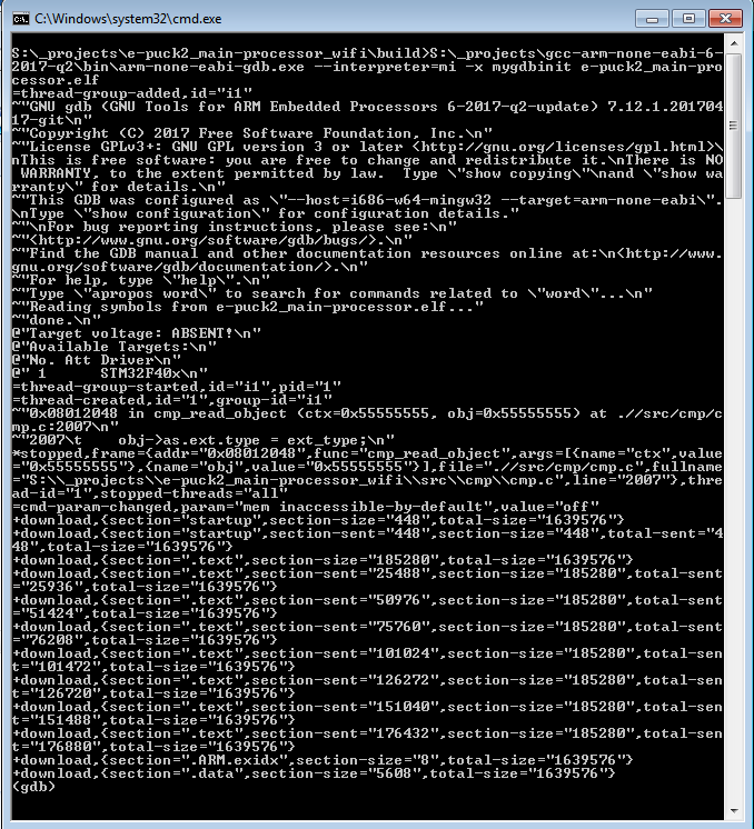
The final line should contain ".data", , and it should all be enclosed at the end with (gdb). You can then close the terminal window.
If you encounter some problem, try to unplug and plug again the USB cable and power cycle the robot, then retry.
Flashing the radio module
In order to update the firmware of the ESP32 WiFi module you need to use a python script called esptool provided by Espressif (manufacturer of the chip). This script was modified to work with the e-puck2 robot and is available from the following link:
- Windows: esptool.exe; Python not required on the system.
- Linux/Mac: esptool.py; Python 3.4 and pySerial 2.5 need to be installed on the system.
Place the script in the same folder as the firmware (composed by 3 bin files: bootloader.bin, ESP32_E-Puck_2.bin and partitions_singleapp.bin) and then issue the following command:
- Windows:
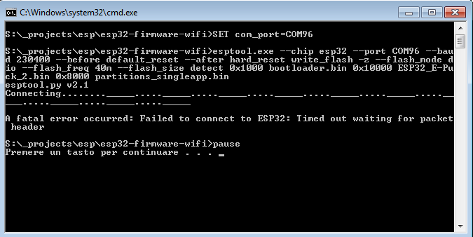
esptool.exe --chip esp32 --port COM96 --baud 230400 --before default_reset --after hard_reset write_flash -z --flash_mode dio --flash_freq 40m --flash_size detect 0x1000 bootloader.bin 0x10000 ESP32_E-Puck_2.bin 0x8000 partitions_singleapp.bin
Alternatively you can download the following batch file esp32-flashing.bat
- Linux/Mac:
python esptool.py --chip esp32 --port COM96 --baud 230400 --before default_reset --after hard_reset write_flash -z --flash_mode dio --flash_freq 40m --flash_size detect 0x1000 bootloader.bin 0x10000 ESP32_E-Puck_2.bin 0x8000 partitions_singleapp.bin
In all cases you need to specify the correct port (with --port parameter) that is the one labeled Serial monitor (see chapter Finding the USB serial ports used).
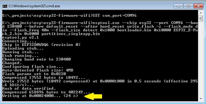
The upload should last about 10-15 seconds and you'll see the progress as shown in the following figure:
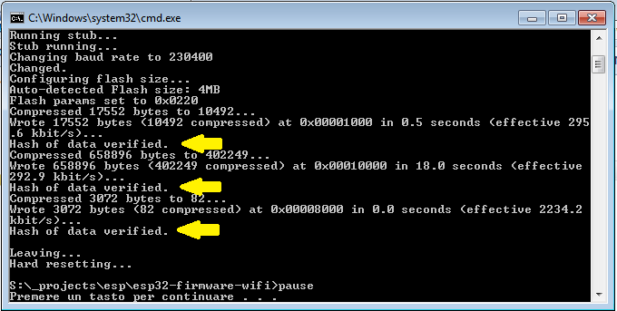
When the upload is complete you'll see that all 3 bin files are uploaded correctly as shown in the following figure:
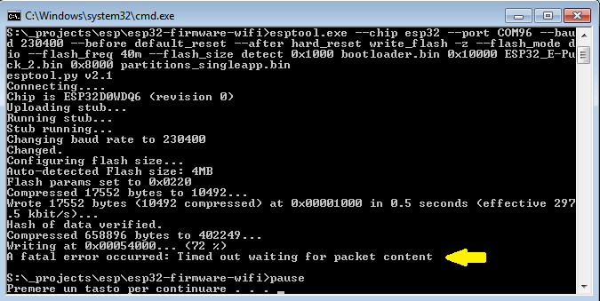
Sometime you could encounter a timeout error as shown in the following figures; in these cases you need to unplug and plug again the USB cable and power cycle the robot, then you can retry.
Connecting to the Bluetooth
The default firmware in the ESP32, the module which provides Bluetooth and Wi-Fi connectivity, creates 3 Bluetooth channels using the RFcomm protocol:
- Channel 1, GDB: port to connect with GDB if the programmer is in mode 1 or 3 (refer to chapter Configuring the Programmer's settings for more information about these modes)
- Channel 2, UART: port to connect to the UART port of the main processor
- Channel 3, SPI: port to connect to the SPI port of the main processor (not yet implemented. Just do an echo for now)
By default, the e-puck2 is not visible when you search for it in the Bluetooth utility of your computer.
To make it visible, it is necessary to hold the USER button (also labeled "esp32" on the electronic board) while turning on the robot with the ON/OFF button.
Then it will be discoverable and you will be able to pair with it.
Note that a prompt could ask you to confirm that the number written on the screen is the same on the e-puck. just ignore this and accept. Otherwise if you are asked for a pin insert 0000.
Windows 7
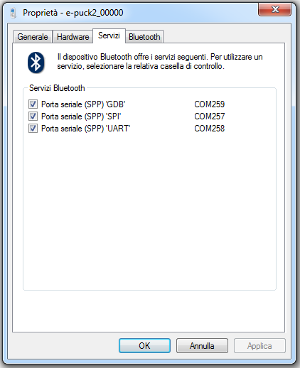
When you pair your computer with the e-puck2, 3 COM ports will be automatically created.
To see which COM port corresponds to which channel you need to open the properties of the paired e-puck2 robot from Bluetooth devices. Then the ports and related channels are listed in the Services tab, as shown in the following figure:
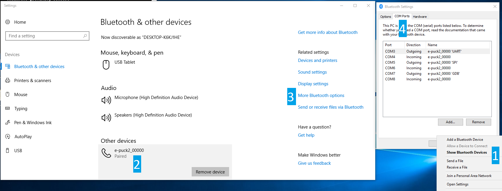
Windows 10
When you pair your computer with the e-puck2, 6 COM ports will be automatically created. The three ports you will use have Outgoing direction and are named e_puck2_xxxxx-GDB, e_puck2_xxxxx-UART, e_puck2_xxxxx-SPI. xxxxx is the ID number of your e-puck2.
To see which COM port corresponds to which channel you need to:
- open the Bluetooth devices manager
- pair with the robot
- click on
More Bluetooth options - the ports and related channels are listed in the
COM Portstab, as shown in the following figure:
Linux
Once paired with the Bluetooth manager, you need to create the port for communicating with the robot by issueing the command:
sudo rfcomm bind /dev/rfcomm0 MAC_ADDR 2
The MAC address is visible from the Bluetooth manager. The parameter 2 indicates the channel, in this case a port for the UART channel is created. If you want to connect to another service you need to change this parameter accordingly (e.g. 1 for GDB and 3 for SPI). Now you can use /dev/rfcomm0 to connect to the robot.
Mac
When you pair your computer with the e-puck2, 3 COM ports will be automatically created: /dev/cu.e-puck2_xxxxx-GDB, /dev/cu.e-puck2_xxxxx-UART and /dev/cu.e-puck2_xxxxx-SPI. xxxxx is the ID number of your e-puck2.
Connecting to the WiFi
At the moment the WiFi channel is used to transfer the image to the computer (a QQVGA color image is transferred) together with the sensors values (magnetometer, selector and tv remote not supported at the moment). The robot is also able to receive commands from the computer (only motors and red LEDs are supported at the moment).
A dedicated configuration is needed to use the WiFi, thus the robot and WiFi module firmwares need to be updated; moreover a PC application is provided to receive the data from the robot and send commands to it:
- main processor firmware (see chapter Flashing the main microcontrollerto update the firmware); put the selector in position 15. If you are interested to the source code, refer to chapter Main microcontroller - WiFi support.
- WiFi module firmware (see chapter Flashing the radio module to update the firmware). If you are interested to the source code, refer to chapter Radio module - WiFi support.
- PC application: Monitor WiFi. If you are interested to the source code, refer to chapter PC interface - WiFi support.
The LED2 is used to indicate the state of the WiFi connection:
- red indicates that the robot is in access point mode (waiting for configuration)
- green indicates that the robot is connected to a network and has received an IP address
- blue (toggling) indicates that the robot is transferring the image to the computer
Network configuration
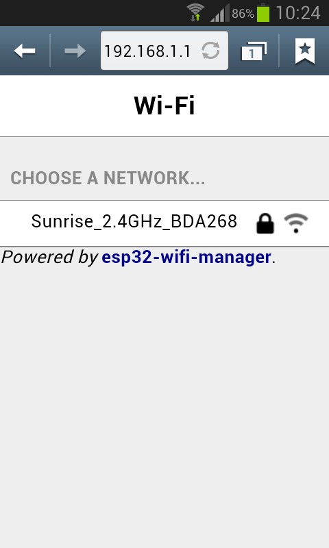
If there is no WiFi configuration saved in flash, then the robot will be in access point mode in order to let the user connect to it and setup a WiFi connection. The LED2 is red.
The access point SSID will be e-puck2_0XXXX where XXXX is the id of the robot; the password to connect to the access point is e-puck2robot.
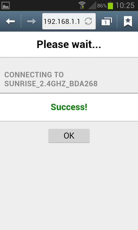
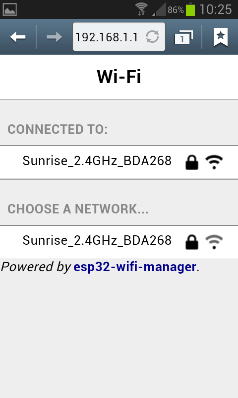
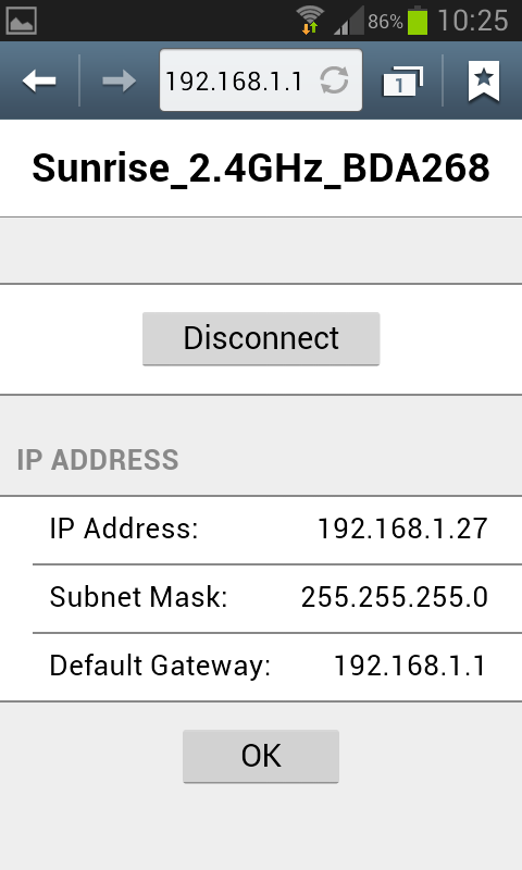
You can use a phone, a tablet or a computer to connect to the robot's WiFi and then you need to open a browser and insert the address 192.168.1.1. The available networks are scanned automatically and listed in the browser page as shown in figure 1. Choose the WiFi signal you want the robot to establish a conection with from the web generated list, and enter the related password; if the password is correct you'll get a message saying that the connection is established as shown in figure 2. After pressing OK you will be redirected to the main page showing the network to which you're connected and the others available nearby as shown in figure 3. If you press on the connected network, then you can see your IP address as shown in figure 4; take note of the address since it will be needed later.
| [1] | [2] | [3] | [4] |
 |
 |
 |
 |
Now the configuration is saved in flash, this means that when the robot is turned on it will read this configuration and try to establish a connection automatically.
Remember that you need to power cycle the robot at least once for the new configuration to be active.
Once the connection is established, the LED2 will be green.
In order to reset the current configuration you need to press the user button for 2 seconds (the LED2 red will turn on), then you need to power cycle the robot to enter access point mode.
Receiving the image
Run the pc application and insert the IP address of the robot. Click on Connect to start receiving the image. The LED2 blue will toggle.
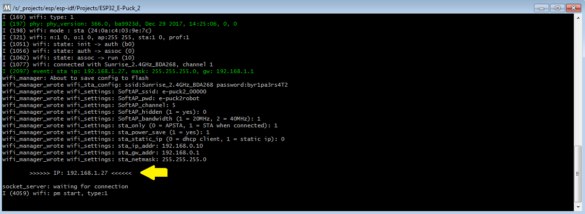
Often the IP address assigned to the robot will remain the same when connecting to the same network, so if you took note of the IP address in section Network configuration probably you're ready to go.
Otherwise you need to connect the robot to the computer with the USB cable and open the port labeled Serial Monitor (see chapter Finding the USB serial ports used). Then power cycle the robot and the IP address will be shown in the terminal (together with others informations), as illustrated in the following figure:
Configuring the PATH variable
The PATH variable is a environment variable used to store a list of the paths to the folders containing the executables we can run in a terminal with Windows, Mac and Linux.
If you want to use the arm-none-eabi toolchain provided inside the Eclipse_e-puck2 package, you have to add it to the PATH variable to be able to call it inside a terminal window.
Setting the PATH variable for Windows :
set PATH=your_installation_path\Eclipse_e-puck2\Tools\gcc-arm-none-eabi-7-2017-q4-major-win32\bin;%PATH%
Setting the PATH variable for Linux :
export PATH=your_installation_path/Eclipse_e-puck2/Tools/gcc-arm-none-eabi-7-2017-q4-major/bin:$PATH
Setting the PATH variable for Mac :
export PATH=your_installation_path/Eclipse_e-puck2.app/Contents/Eclipse_e-puck2/Tools/gcc-arm-none-eabi-7-2017-q4-major/bin:$PATH
What is important to know is that this procedure is temporary. It applies only to the terminal window used to type it. If you open a new terminal window or close this one, you will have to set again the PATH variable.
Note : The arm-none-eabi version can differ from the one given in this example. It could be needed to adapt the path to the correct version.
Software
PC interface
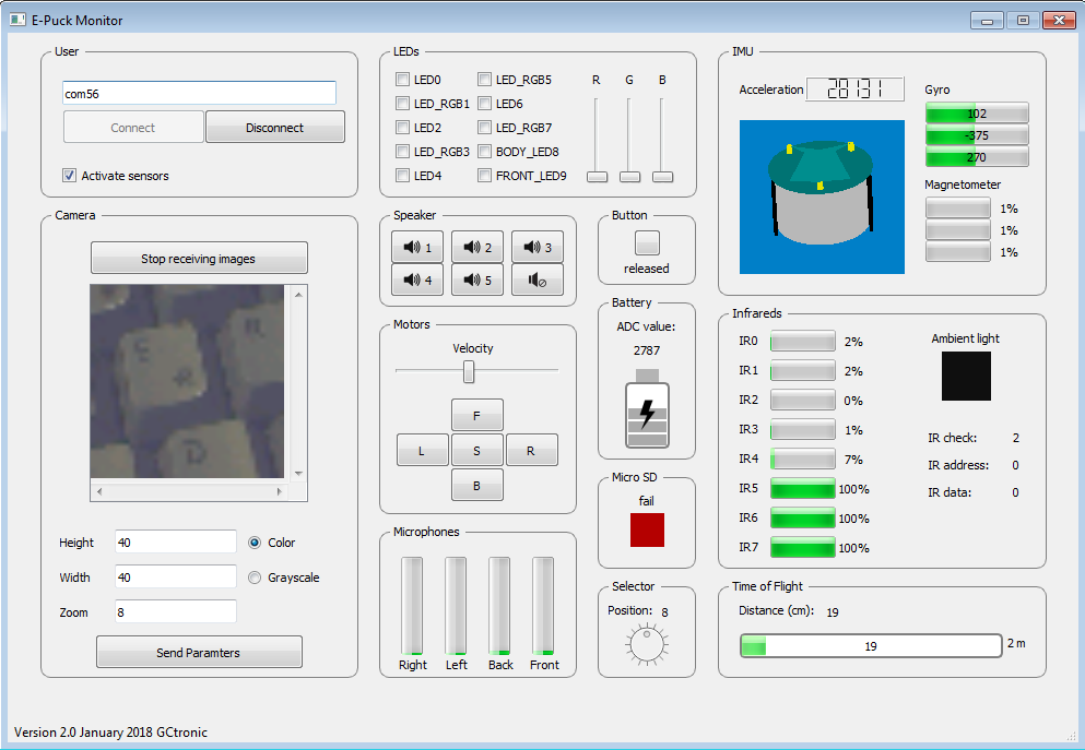
An interface running on a computer and connecting to the e-puck2 either through Bluetooth (selector position 3) or via USB (selector position 8) based on the advanced sercom protocol was developed; from this interface it's possible to have information about all the sensors, receive camera images and control the leds and motors. The source code is available from the repository https://github.com/e-puck2/monitor.
Available executables:
- Windows executable: tested on Windows 7 and Windows 10
- Max OS X executable
On Linux remember to apply the configuration explained in the chapter Installation for Linux - Serial Port in order to access the serial port.
WiFi support
A dedicated WiFi version of the monitor application was developed to communicate with the robot through TCP protocol.
For more information about the communication protocol, refer to section WiFi communication protocol.
The source code can be downloaded with the command git clone -b wifi --recursive https://github.com/e-puck2/monitor.git
A Windows executable is available here Monitor WiFi for Windows.
Main microcontroller firmware
The robot is initially programmed with a firmware that includes many demos that could be started based on the selector position:
- Selector position 0: Aseba
- Selector position 1: Shell
- Selector position 2: Read proximity sensors
- Selector position 3: Asercom protocol v2 (BT)
- Selector positoin 4: Range and bearing extension (receiver)
- Selector position 5: Range and bearing extension (transmitter)
- Selector position 6: ESP32 UART communication test
- Selector position 7: ...
- Selector position 8: Asercom protocol v2 (USB)
- Selector position 9: Asercom protocol (BT)
- Selector position 10: This position is used to work with the gumstix extension.
- Selector position 11: Simple obstacle avoidance + some animation
- Selector position 12: Hardware test
- Selector position 13: LEDs reflect orientation of the robot
- Selector position 14: Read magnetometer sensor
- Selector position 15: ...
The source code is available in the git repo https://github.com/e-puck2/e-puck2_main-processor.
The pre-built firmware is available here e-puck2-firmware.
Flashing the main microcontroller
Refer to section Flashing the main microcontroller.
WiFi support
At the moment there is a separate firmware if the user want to use the WiFi; this firmware was specifically developed to transmit the camera image and sensors to the computer and receive commands from the computer (only motors and red LEDs are supported at the moment).
In the future the WiFi support will be integrated in the standard firmware.
The source code can be downloaded with the command git clone -b wifi --recursive https://github.com/e-puck2/e-puck2_main-processor.git
The pre-built firmware is available here e-puck2-firmware_wifi.
Library
The library contains all the functions needed to interact with the robot's sensors and actuators; the project includes also the basic standard firmware that shows how to use these functions.
A snapshot of the library can be donwloaded from e-puck2_main-processor_snapshot_16.02.18.zip.
Otherwise the latest version can be downloaded with the command: git clone --recursive https://github.com/e-puck2/e-puck2_main-processor.git
If you don't have git, you can issue the command: sudo apt-get install git.
Programmer firmware
This firmware is based on Black Magic Probe programmer/debugger.
The source code can be downloaded with the command git clone --recursive -b e-puck-2.0_E https://github.com/e-puck2/e-puck2-programmer
In order to build the firmware you need to issue the following commands form the main repo directory:
make clean
make PROBE_HOST=e-puck/2.0
The result is a bin file named blackmagic.bin that you can find in the src directory.
The pre-built firmware is available here programmer-firmware.bin; it is also available in dfu format here programmer-firmware.dfu.
Flashing the programmer
First of all to update the programmer's firmware you need to enter DFU mode (device firmware upgrade). To do it refer to section Using the DFU, in particular Note 2.
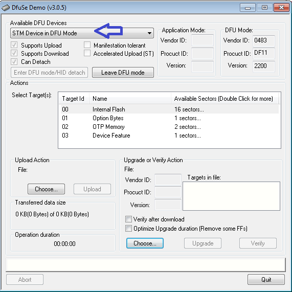
The programmer will be recognized as STM Device in DFU Mode device.
Linux
In order to update the programmer firmware you need an utility called dfu-util.
To install it issue the command sudo apt-get install dfu-util.
Then issue the following command to upload the firmware: sudo dfu-util -d 0483:df11 -a 0 -s 0x08000000 -D programmer-firmware.bin
Windows
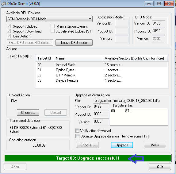
For Windows users it is available an application called DfuSe released by STMicroelectronics. You can download it from DfuSe_V3.0.5.zip.
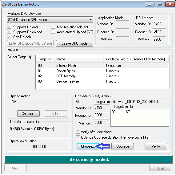
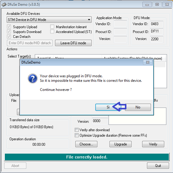
When the program is started, the programmer in DFU mode will be automatically detected as shown in figure 1. Then you need to open the compiled firmware by clicking on choose and then locating the file, as shown in figure 2. Now click on the upgrade button, a warning message will be shown, confirm the action by clicking on yes as shown in figure 3. If all is ok you'll be prompted with a message saying that the upgrade was successfull as shown in figure 4.
| [1] | [2] | [3] | [4] |
 |
 |
 |
 |
Radio module firmware
The firmware support Bluetooth communication.
The source code can be downloaded with the command git clone --recursive https://github.com/e-puck2/esp-idf.git
In order to build the firmware you need to install the toolchain, refer to http://esp-idf.readthedocs.io/en/latest/get-started/#setup-toolchain. Once installed you can issue the command make flash from the directory Projects\ESP32_E-Puck_2 to build the firmware. For more information have a look at http://esp-idf.readthedocs.io/en/latest/get-started/#build-and-flash.
The pre-built firmware is available here esp32-firmware.zip.
Flashing the radio module
Refer to section Flashing the radio module.
WiFi support
At the moment there is a separate firmware if the user want to use the WiFi; this firmware was specifically developed to transmit the camera image and sensors to the computer and receive commands from the computer (only motors and red LEDs are supported at the moment).
In the future the WiFi support will be integrated in the standard firmware.
The source code can be downloaded with the command git clone -b wifi --recursive https://github.com/e-puck2/esp-idf.git
The pre-built firmware is available here esp32-firmware_wifi.zip.
Advanced usage
Configuring the Programmer's settings
The on-board programmer of the e-puck2 is based on the Blackmagic probe open source project firmware.
Some functionalities has been added on top of the original project to be able to control some functions of the robot, for example the power on or power off.
To access to the available commands of the programmer, it is needed to connect to the programmer with a GDB console.
To do so, you have to type the following command in a terminal window with the com port used by the 'e-puck2 GDB Server port of your e-puck2 :
arm-none-eabi-gdb
target extended-remote your_gdb_com_port
Once connected to the programmer with GDB, you can type
monitor help
or
mon help
to print the available commands of the programmer.
One command in particular is useful, which is mon select_mode. It is used to select in which mode the e-puck2 Serial Monitor com port will work.
mode 1 = the serial monitor is connected to the UART port of the main processor
mode 2 = the serial monitor is connected to the UART of the ESP32
mode 3 = the serial monitor works as a Aseba CAN to USB translator
The choice made for the mode is the only setting that is stored in a flash zone of the programmer, which means the choice is remembered, even if the robot is completely turned off.
Note : in mode 1 and 3, GDB can be used over the bluetooth connection of the e-puck2. But is is much slower than with USB and it doesn't work with Windows due to GDB limitations on this OS.
By being connected with GDB, you can also use the standard GDB command to program and debug the main processor of the e-puck2.
Using the DFU
To put the e-puck2 into DFU, it is needed to turn it on while keeping pressed the "407 boot" button located under the electronic card on the left side of the robot.
The robot will appear as "STM32 BOOTLOADER" in the USB devices.
Once in DFU, you can program it with dfu-util using the following command :
dfu-util -d 0483:df11 -a 0 -s 0x08000000 -D your_firmware.bin
See the manual page of dfu-util for further information on how to use it.
Note: For windows, it is needed to install a libusbK driver for the DFU device.
You can use the Zadig program located in the Eclipse_e-puck2\Tools\ (if you installed Eclipse_e-puck2 package) to install it.
Follow the same procedure as explained above under the Installation drivers section using libusbK driver instead of USB Serial (CDC).
Note 2: It is also possible to put the programmer in DFU by contacting two pinholes together while inserting the USB cable (no need to turn on the robot).
It is used to update the firmware of the programmer.
The two pin holes are located near the USB connector of the e-puck2, see the photo below.
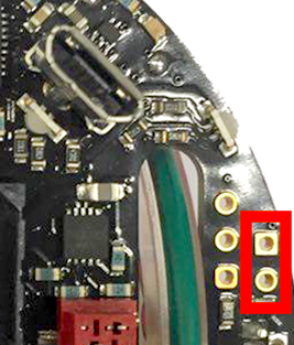
- Location of the pin holes to put the programmer into DFU
WiFi communication protocol
The communication is based on TCP; the robot create a TCP server and wait for a connection.
Each packet is identified by an ID (1 byte). The following IDs are used to send data from the robot to the computer:
- 0x00 = reserved
- 0x01 = QQVGA color image packet (only the first segment includes this id); packet size (without id) = 38400 bytes; image format = RGB565
- 0x02 = sensors packet; packet size (without id) = 98 bytes; the format of the returned values are based on the asercom protocol:

- 0x03 = empty packet (only id is sent); this is used as an acknowledgment for the commands packet when no sensors and no image is requested
The following IDs are used to send data from the computer to the robot:
- 0x80 = commands packet; packet size (without id) = 20 bytes:
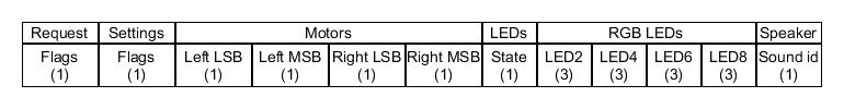
- request:
- bit0: 0=stop image stream; 1=start image stream
- bit1: 0=stop sensors stream; 1=start sensors stream
- settings:
- bit0: 1=calibrate IR proximity sensors
- bit1: 0=disable onboard obstacle avoidance; 1=enable onboard obstacle avoidance (not implemented yet)
- bit2: 0=set motors speed; 1=set motors steps (position)
- left and right: when bit2 of
settingsfield is0, then this is the desired motors speed (-1000..1000); when1then this is the value that will be set as motors position (steps) - LEDs: 0=off; 1=on; 2=toggle
- bit0: 0=LED1 off; 1=LED1 on
- bit1: 0=LED3 off; 1=LED3 on
- bit2: 0=LED5 off; 1=LED5 on
- bit3: 0=LED7 off; 1=LED7 on
- bit4: 0=body LED off; 1=body LED on
- bit5: 0=front LED off; 1=front LED on
- RGB LEDs: for each LED, it is specified in sequence the value of red, green and blue (0...100)
- sound id: 0x01=MARIO, 0x02=UNDERWOLRD, 0x04=STARWARS, 0x08=4KHz, 0x10=10KHz, 0x20=stop sound
- request:
For example to receive the camera image (stream) the following steps need to be followed:
1) connect to the robot through TCP
2) send the command packet:
0x80 0x01 0x00 0x00 0x00 0x00 0x00 0x00 0x00 0x00 0x00 0x00 0x00 0x00 0x00 0x00 0x00 0x00 0x00 0x00 0x00
3) read the ID (1 byte) and the QQVGA color image pakcet (38400 bytes)
4) go to step 3