e-puck2 and e-puck2 PC side development: Difference between pages
| Line 1: | Line 1: | ||
[{{fullurl:e-puck2}} e-puck2 main wiki]<br/> | |||
=Robot configuration= | |||
This section explains how to configure the robot based on the communication channel you will use for your developments, thus you need to read only one of the following sections, but it would be better if you spend a bit of time reading them all in order to have a full understanding of the available configurations. | |||
==Bluetooth and USB== | |||
The main microcontroller and radio module of the robot are initially programmed with firmwares that together support Bluetooth and USB communication.<br/> | |||
If the main microcontroller and radio module aren't programmed with the factory firmware or if you want to be sure to have the last firmwares on the robot, you need to program them with the last factory firmwares: | |||
* for the main microcontroller, refer to section [http://www.gctronic.com/doc/index.php?title=e-puck2#Firmware_update main microcontroller firmware update] | |||
* for the radio module, refer to section [http://www.gctronic.com/doc/index.php?title=e-puck2#Firmware_update_2 radio module firmware update] | |||
When you want to interact with the robot from the computer you need to place the selector in position 3 if you want to work with Bluetooth, or in position 8 if you want to work with USB. <br/> | |||
Section [http://www.gctronic.com/doc/index.php?title=e-puck2_PC_side_development#Connecting_to_the_Bluetooth Connecting to the Bluetooth] gives step by step instructions on how to accomplish your first Bluetooth connection with the robot.<br/> | |||
Section [http://www.gctronic.com/doc/index.php?title=e-puck2#PC_interface PC interface] gives step by step instructions on how to connect the robot with the computer via USB.<br/> | |||
Once you tested the connection with the robot and the computer, you can start developing your own application by looking at the details behind the communication protocol. Both communication channels use the same protocol called <code>advanced sercom v2</code>, refer to section [http://www.gctronic.com/doc/index.php?title=e-puck2_PC_side_development#Bluetooth_and_USB_2 Communication protocol: BT and USB] for detailed information about this protocol.<br/> | |||
==WiFi== | |||
For working with the WiFi, the main microcontroller and radio module must be programmed with dedicated firmwares (not the factory ones): | |||
* [http://projects.gctronic.com/epuck2/e-puck2_main-processor_wifi_afaa618.elf main microcontroller wifi firmware], for information on how to update the firmware refer to section [http://www.gctronic.com/doc/index.php?title=e-puck2#Firmware_update main microcontroller firmware update] | |||
* [http://projects.gctronic.com/epuck2/esp32-firmware-wifi-7bf44de.zip radio module wifi firmware], for information on how to update the firmware refer to section [http://www.gctronic.com/doc/index.php?title=e-puck2#Firmware_update_2 radio module firmware update] | |||
Put the selector in position 15.<br/> | |||
Section [http://www.gctronic.com/doc/index.php?title=e-puck2_PC_side_development#Connecting_to_the_WiFi Connecting to the WiFi] gives step by step instructions on how to accomplish your first WiFi connection with the robot.<br/> | |||
The communication protocol is described in detail in the section [http://www.gctronic.com/doc/index.php?title=e-puck2_PC_side_development#WiFi_2 Communication protocol: WiFi].<br/> | |||
The | |||
=Connecting to the Bluetooth= | |||
The factory firmware of the radio module creates 3 Bluetooth channels using the RFcomm protocol when the robot is paired with the computer: | |||
# Channel 1, GDB: port to connect with GDB if the programmer is in mode 1 or 3 (refer to chapter [http://www.gctronic.com/doc/index.php?title=e-puck2_programmer_development#Configuring_the_Programmer.27s_settings Configuring the Programmer's settings] for more information about these modes) | |||
# Channel 2, UART: port to connect to the UART port of the main processor | |||
# Channel 3, SPI: port to connect to the SPI port of the main processor (not yet implemented. Just do an echo for now) | |||
By default, the e-puck2 is not visible when you search for it in the Bluetooth utility of your computer.<br> | |||
To | '''To make it visible, it is necessary to hold the USER button (also labeled "esp32" on the electronic board) while turning on the robot with the ON/OFF button.'''<br> | ||
::<span class="plain links">[http://projects.gctronic.com/epuck2/wiki_images/e-puck2- | ::<span class="plain links">[http://projects.gctronic.com/epuck2/wiki_images/e-puck2-bt-pair.png <img width=250 src="http://projects.gctronic.com/epuck2/wiki_images/e-puck2-bt-pair-small.png">]</span><br/> | ||
Then it will be discoverable and you will be able to pair with it.<br> | |||
Note that a prompt could ask you to confirm that the number written on the screen is the same on the e-puck. just ignore this and accept. Otherwise if you are asked for a pin insert 0000. | |||
== | ==Windows 7== | ||
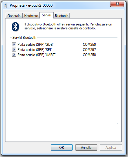
When you pair your computer with the e-puck2, 3 COM ports will be automatically created. | |||
To see which COM port corresponds to which channel you need to open the properties of the paired e-puck2 robot from <code>Bluetooth devices</code>. Then the ports and related channels are listed in the <code>Services</code> tab, as shown in the following figure:<br/> | |||
<span class="plain links">[http://projects.gctronic.com/epuck2/wiki_images/BT-connection-win7.png <img width=300 src="http://projects.gctronic.com/epuck2/wiki_images/BT-connection-win7.png">]</span> | |||
::<span class="plain links">[http://projects.gctronic.com/epuck2/wiki_images/ | ==Windows 10== | ||
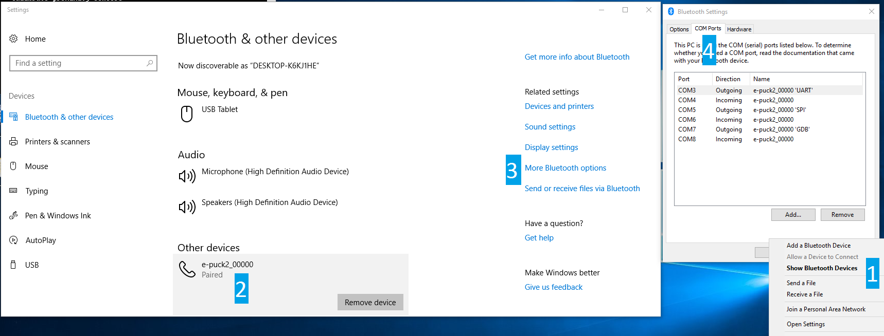
When you pair your computer with the e-puck2, 6 COM ports will be automatically created. The three ports you will use have <code>Outgoing</code> direction and are named <code>e_puck2_xxxxx-GDB</code>, <code>e_puck2_xxxxx-UART</code>, <code>e_puck2_xxxxx-SPI</code>. <code>xxxxx</code> is the ID number of your e-puck2.<br/> | |||
To see which COM port corresponds to which channel you need to: | |||
# open the Bluetooth devices manager | |||
# pair with the robot | |||
# click on <code>More Bluetooth options</code> | |||
# the ports and related channels are listed in the <code>COM Ports</code> tab, as shown in the following figure:<br/> | |||
:<span class="plain links">[http://projects.gctronic.com/epuck2/wiki_images/BT-connection-win10.png <img height=300 src="http://projects.gctronic.com/epuck2/wiki_images/BT-connection-win10.png">]</span> | |||
==Linux== | |||
Once paired with the Bluetooth manager, you need to create the port for communicating with the robot by issueing the command: <br/> | |||
<code>sudo rfcomm bind /dev/rfcomm0 MAC_ADDR 2</code><br/> | |||
The MAC address is visible from the Bluetooth manager. The parameter <code>2</code> indicates the channel, in this case a port for the <code>UART</code> channel is created. If you want to connect to another service you need to change this parameter accordingly (e.g. <code>1</code> for <code>GDB</code> and <code>3</code> for <code>SPI</code>). Now you can use <code>/dev/rfcomm0</code> to connect to the robot. | |||
==Mac== | |||
When you pair your computer with the e-puck2, 3 COM ports will be automatically created: <code>/dev/cu.e-puck2_xxxxx-GDB</code>, <code>/dev/cu.e-puck2_xxxxx-UART</code> and <code>/dev/cu.e-puck2_xxxxx-SPI</code>. xxxxx is the ID number of your e-puck2. | |||
==Testing the Bluetooth connection== | |||
You need to download the PC application provided in section [http://www.gctronic.com/doc/index.php?title=e-puck2#Available_executables PC interface: available executables].<br/> | |||
In the connection textfield you need to enter the UART channel port, for example: | |||
* Windows 7: <code>COM258</code> | |||
* Windows 10: <code>e_puck2_xxxxx-UART</code> | |||
* Linux: <code>/dev/rfcomm0</code> | |||
* Mac: <code>/dev/cu.e-puck2_xxxxx-UART</code> | |||
and then click <code>Connect</code>. <br/> | |||
You should start receiving sensors data and you can send commands to the robot.<br/> | |||
Alternatively you can also use a simple terminal program (e.g. <code>realterm</code> in Windows) instead of the PC application, then you can issue manually the commands to receive sensors data or for setting the actuators (once connected, type <code>h + ENTER</code> for a list of availables commands). | |||
= | =Connecting to the WiFi= | ||
The | The WiFi channel is used to communicate with robot faster than with Bluetooth. At the moment a QQVGA (160x120) color image is transferred to the computer together with the sensors values at about 10 Hz; of course the robot is also able to receive commands from the computer.<br/> | ||
In order to communicate with the robot through WiFi, first you need to configure the network parameters on the robot by connecting directly to it, since the robot is initially configured in access point mode, as explained in the following section. Once the configuration is saved on the robot, it will then connect automatically to the network and you can connect to it. | |||
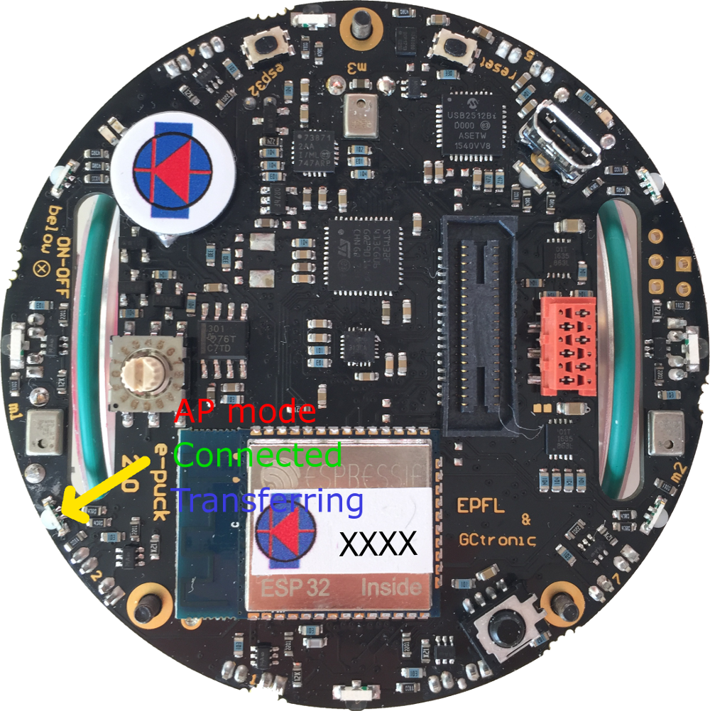
The LED2 is used to indicate the state of the WiFi connection: | |||
* red indicates that the robot is in ''access point mode'' (waiting for configuration) | |||
* green indicates that the robot is connected to a network and has received an IP address | |||
* blue (toggling) indicates that the robot is transferring the image to the computer | |||
* off when the robot cannot connect to the saved configuration | |||
::<span class="plain links">[http://projects.gctronic.com/epuck2/wiki_images/e-puck2-wifi-led.png <img width=250 src="http://projects.gctronic.com/epuck2/wiki_images/e-puck2-wifi-led-small.png">]</span><br/> | |||
==Network configuration== | |||
If there is no WiFi configuration saved in flash, then the robot will be in ''access point mode'' in order to let the user connect to it and setup a WiFi connection. The LED2 is red. | |||
The | The access point SSID will be <code>e-puck2_0XXXX</code> where <code>XXXX</code> is the id of the robot; the password to connect to the access point is <code>e-puck2robot</code>.<br/> | ||
You can use a phone, a tablet or a computer to connect to the robot's WiFi and then you need to open a browser and insert the address <code>192.168.1.1</code>. The available networks are scanned automatically and listed in the browser page as shown in ''figure 1''. Choose the WiFi signal you want the robot to establish a conection with from the web generated list, and enter the related password; if the password is correct you'll get a message saying that the connection is established as shown in ''figure 2''. After pressing <code>OK</code> you will be redirected to the main page showing the network to which you're connected and the others available nearby as shown in ''figure 3''. If you press on the connected network, then you can see your IP address as shown in ''figure 4''; <b>take note of the address since it will be needed later</b>.<br/> | |||
<span class="plainlinks"> | |||
<table> | |||
<tr> | |||
<td align="center">[1]</td> | |||
<td align="center">[2]</td> | |||
<td align="center">[3]</td> | |||
<td align="center">[4]</td> | |||
</tr> | |||
<tr> | |||
<td>[http://projects.gctronic.com/epuck2/wiki_images/esp32-wifi-setup1.png <img width=150 src="http://projects.gctronic.com/epuck2/wiki_images/esp32-wifi-setup1.png">]</td> | |||
<td>[http://projects.gctronic.com/epuck2/wiki_images/esp32-wifi-setup2.png <img width=150 src="http://projects.gctronic.com/epuck2/wiki_images/esp32-wifi-setup2.png">]</td> | |||
<td>[http://projects.gctronic.com/epuck2/wiki_images/esp32-wifi-setup3.png <img width=150 src="http://projects.gctronic.com/epuck2/wiki_images/esp32-wifi-setup3.png">]</td> | |||
<td>[http://projects.gctronic.com/epuck2/wiki_images/esp32-wifi-setup4.png <img width=150 src="http://projects.gctronic.com/epuck2/wiki_images/esp32-wifi-setup4.png">]</td> | |||
</tr> | |||
</table> | |||
</span><br/> | |||
Now the configuration is saved in flash, this means that when the robot is turned on it will read this configuration and try to establish a connection automatically.<br/> | |||
Remember that you need to power cycle the robot at least once for the new configuration to be active.<br/> | |||
Once the connection is established, the LED2 will be green.<br/> | |||
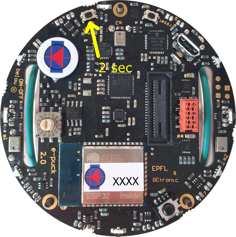
In order to reset the current configuration you need to press the user button for 2 seconds (the LED2 red will turn on), then you need to power cycle the robot to enter ''access point mode''. | |||
= | ::<span class="plain links">[http://projects.gctronic.com/epuck2/wiki_images/e-puck2-wifi-reset.png <img width=250 src="http://projects.gctronic.com/epuck2/wiki_images/e-puck2-wifi-reset-small.png">]</span><br/> | ||
== | ==Finding the IP address== | ||
: | Often the IP address assigned to the robot will remain the same when connecting to the same network, so if you took note of the IP address in section [http://www.gctronic.com/doc/index.php?title=e-puck2#Network_configuration Network configuration] you're ready to go to the next section. <br/> | ||
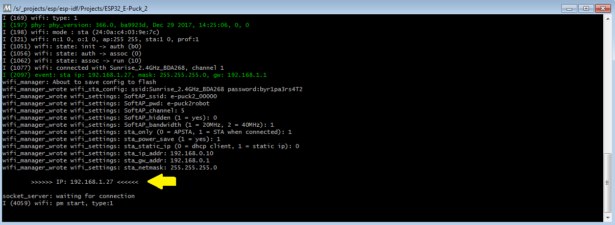
Otherwise you need to connect the robot to the computer with the USB cable, open a terminal and connect to the port labeled <code>Serial Monitor</code> (see chapter [http://www.gctronic.com/doc/index.php?title=e-puck2#Finding_the_USB_serial_ports_used Finding the USB serial ports used]). Then power cycle the robot and the IP address will be shown in the terminal (together with others informations), as illustrated in the following figure:<br/> | |||
<span class="plain links">[http://projects.gctronic.com/epuck2/wiki_images/esp32-wifi-setup5.png <img width=500 src="http://projects.gctronic.com/epuck2/wiki_images/esp32-wifi-setup5.png">]</span> | |||
: | |||
==Testing the WiFi connection== | |||
A dedicated WiFi version of the PC application was developed to communicate with the robot through TCP protocol. You can download the executable from one of the following links: | |||
== | * [http://projects.gctronic.com/epuck2/monitor_wifi_27dddd4.zip Windows executable - WiFi] | ||
* Mac (not available yet) | |||
A PC application was developed to | |||
* [http://projects.gctronic.com/epuck2/ | |||
* | |||
* Linux (not available yet) | * Linux (not available yet) | ||
If you are interested to the source code, you can download it with the command <code>git clone -b wifi --recursive https://github.com/e-puck2/monitor.git</code><br/> | |||
Run the PC application, insert the IP address of the robot in the connection textfield and then click on the <code>Connect</code> button. You should start receiving sensors data and you can send commands to the robot. The LED2 blue will toggle.<br/> | |||
=Communication protocol= | |||
This section is the hardest part to understand. It outlines all the details about the communication protocols that you'll need to implement in order to communicate with the robot form the computer. So spend a bit of time reading and re-reading this section in order to grasp completely all the details. | |||
== | ==Bluetooth and USB== | ||
The communication protocol is based on the [http://www.gctronic.com/doc/index.php/Advanced_sercom_protocol advanced sercom protocol], used with the e-puck1.x robot. The <code>advanced sercom v2</code> includes all the commands available in the <code>advanced sercom</code> protocol and add some additional commands to handle the new features of the e-puck2 robot. In particular here are the new commands: | |||
{| border="1" cellpadding="10" cellspacing="0" | |||
!Command | |||
!Description | |||
!Return value / set value | |||
|- | |||
|<code>0x08</code> | |||
|Get all sensors | |||
|see section [http://www.gctronic.com/doc/index.php?title=e-puck2_PC_side_development#WiFi_2 Communication protocol: WiFi] | |||
|- | |||
|<code>0x09</code> | |||
|Set all actuators | |||
|see section [http://www.gctronic.com/doc/index.php?title=e-puck2_PC_side_development#WiFi_2 Communication protocol: WiFi] | |||
|- | |||
|<code>0x0A</code> | |||
|Set RGB LEDs | |||
|<code>[LED2_red][LED2_blue][LED2_green][LED4_red][LED4_blue][LED4_green][LED6_red][LED6_blue][LED6_green][LED8_red][LED8_blue][LED8_green]</code> | |||
|- | |||
|<code>0x0B</code> | |||
|Get button state: 0 = not pressed, 1 = pressed | |||
|<code>[STATE]</code> | |||
|- | |||
|<code>0x0C</code> | |||
|Get all 4 microphones volumes | |||
|<code>[MIC0_LSB][MIC0_MSB][MIC1_LSB][MIC1_MSB][MIC2_LSB][MIC2_MSB][MIC3_LSB][MIC3_MSB]</code> | |||
|- | |||
|<code>0x0D</code> | |||
|Get distance from ToF sensor (millimeters) | |||
|<code>[DIST_LSB][DIST_MSB]</code> | |||
|- | |||
|<code>0x0E</code> | |||
|Get SD state: 0 = micro sd not connected, 1 = micro sd connected | |||
|<code>[STATE]</code> | |||
|} | |||
==WiFi== | |||
The communication is based on TCP; the robot create a TCP server and wait for a connection.<br/> | |||
=== | Each packet is identified by an ID (1 byte). The following IDs are used to send data from the robot to the computer: | ||
* 0x00 = reserved | |||
* 0x01 = QQVGA color image packet (only the first segment includes this id); packet size (without id) = 38400 bytes; image format = RGB565 | |||
* 0x02 = sensors packet; packet size (without id) = 104 bytes; the format of the returned values are based on the [http://www.gctronic.com/doc/index.php/Advanced_sercom_protocol advanced sercom protocol] and are compatible with e-puck1.x: | |||
:<span class="plain links">[http://projects.gctronic.com/epuck2/wiki_images/packet-format-robot-to-pc.jpg <img width=1150 src="http://projects.gctronic.com/epuck2/wiki_images/packet-format-robot-to-pc.jpg">]</span><br/> | |||
* | :*Acc: raw axes values, between -1500 and 1500, resolution is +-2g | ||
:*Acceleration: acceleration magnitude <img width=70 src="http://projects.gctronic.com/epuck2/wiki_images/3dvector-magnitude.png">, between 0.0 and about 2600.0 (~3.46 g) | |||
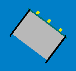
:*Orientation: between 0.0 and 360.0 degrees <table><tr><td align="center">0.0 deg</td><td align="center">90.0 deg</td><td align="center">180 deg</td><td align="center">270 deg</td></tr><tr><td><img width=80 src="http://projects.gctronic.com/epuck2/wiki_images/orientation0.png"></td><td><img width=80 src="http://projects.gctronic.com/epuck2/wiki_images/orientation90.png"></td><td><img width=80 src="http://projects.gctronic.com/epuck2/wiki_images/orientation180.png"></td><td><img width=80 src="http://projects.gctronic.com/epuck2/wiki_images/orientation270.png"></td></tr></table> | |||
:*Inclination: between 0.0 and 90.0 degrees (when tilted in any direction)<table><tr><td align="center">0.0 deg</td><td align="center">90.0 deg</td></tr><tr><td><img width=80 src="http://projects.gctronic.com/epuck2/wiki_images/inclination0.png"></td><td><img width=80 src="http://projects.gctronic.com/epuck2/wiki_images/inclination90.png"></td></tr></table> | |||
* | :*Gyro: raw axes values, between -32768 and 32767, range is +-250dps | ||
:*Magnetometer: raw axes values, between -32760 and 32760, range is +-4912 uT (magnetic flux density expressed in micro Tesla) | |||
:*Temp: temperature given in Celsius degrees | |||
:*IR proximity: between 0 (no objects detected) and 4095 (object near the sensor) | |||
:*IR ambient: between 0 (strong light) and 4095 (dark) | |||
:*ToF distance: distance given in millimeters | |||
:*Mic volume: between 0 and 4095 | |||
:*Motors steps: 1000 steps per wheel revolution | |||
:*Battery: | |||
:*uSD state: 1 if the micro sd is present and can be read/write, 0 otherwise | |||
:*TV remote data: RC5 protocol | |||
:*Selector position: between 0 and 15 | |||
:*Ground proximity: between 0 (no surface at all or not reflective surface e.g. black) and 1023 (very reflective surface e.g. white) | |||
:*Ground ambient: between 0 (strong light) and 1023 (dark) | |||
:*Button state: 1 button pressed, 0 button released | |||
* 0x03 = empty packet (only id is sent); this is used as an acknowledgment for the commands packet when no sensors and no image is requested | |||
The following IDs are used to send data from the computer to the robot: | |||
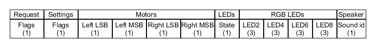
* 0x80 = commands packet; packet size (without id) = 20 bytes: | |||
= | :<span class="plain links">[http://projects.gctronic.com/epuck2/wiki_images/packet-format-pc-to-robot.jpg <img width=600 src="http://projects.gctronic.com/epuck2/wiki_images/packet-format-pc-to-robot.jpg">]</span><br/> | ||
= | :*request: | ||
:** bit0: 0=stop image stream; 1=start image stream | |||
:** bit1: 0=stop sensors stream; 1=start sensors stream | |||
:*settings: | |||
:** bit0: 1=calibrate IR proximity sensors | |||
:** bit1: 0=disable onboard obstacle avoidance; 1=enable onboard obstacle avoidance (not implemented yet) | |||
:** bit2: 0=set motors speed; 1=set motors steps (position) | |||
:*left and right: when bit2 of <code>settings</code> field is <code>0</code>, then this is the desired motors speed (-1000..1000); when <code>1</code> then this is the value that will be set as motors position (steps) | |||
:*LEDs: 0=off; 1=on; 2=toggle | |||
:** bit0: 0=LED1 off; 1=LED1 on | |||
:** bit1: 0=LED3 off; 1=LED3 on | |||
:** bit2: 0=LED5 off; 1=LED5 on | |||
:** bit3: 0=LED7 off; 1=LED7 on | |||
:** bit4: 0=body LED off; 1=body LED on | |||
:** bit5: 0=front LED off; 1=front LED on | |||
:*RGB LEDs: for each LED, it is specified in sequence the value of red, green and blue (0...100) | |||
:* sound id: 0x01=MARIO, 0x02=UNDERWOLRD, 0x04=STARWARS, 0x08=4KHz, 0x10=10KHz, 0x20=stop sound | |||
For example to receive the camera image (stream) the following steps need to be followed:<br/> | |||
1) connect to the robot through TCP<br/> | |||
2) send the command packet: | |||
:{| border="1" | |||
|0x80 | |||
|0x01 | |||
|0x00 | |||
|0x00 | |||
|0x00 | |||
|0x00 | |||
|0x00 | |||
|0x00 | |||
|0x00 | |||
|0x00 | |||
|0x00 | |||
|0x00 | |||
|0x00 | |||
|0x00 | |||
|0x00 | |||
|0x00 | |||
|0x00 | |||
|0x00 | |||
|0x00 | |||
|0x00 | |||
|0x00 | |||
|} | |||
3) read the ID (1 byte) and the QQVGA color image pakcet (38400 bytes)<br/> | |||
4) go to step 3 | |||
== | =Webots= | ||
TBD | |||
= | =ROS= | ||
TBD | |||
Revision as of 08:34, 9 August 2018
Robot configuration
This section explains how to configure the robot based on the communication channel you will use for your developments, thus you need to read only one of the following sections, but it would be better if you spend a bit of time reading them all in order to have a full understanding of the available configurations.
Bluetooth and USB
The main microcontroller and radio module of the robot are initially programmed with firmwares that together support Bluetooth and USB communication.
If the main microcontroller and radio module aren't programmed with the factory firmware or if you want to be sure to have the last firmwares on the robot, you need to program them with the last factory firmwares:
- for the main microcontroller, refer to section main microcontroller firmware update
- for the radio module, refer to section radio module firmware update
When you want to interact with the robot from the computer you need to place the selector in position 3 if you want to work with Bluetooth, or in position 8 if you want to work with USB.
Section Connecting to the Bluetooth gives step by step instructions on how to accomplish your first Bluetooth connection with the robot.
Section PC interface gives step by step instructions on how to connect the robot with the computer via USB.
Once you tested the connection with the robot and the computer, you can start developing your own application by looking at the details behind the communication protocol. Both communication channels use the same protocol called advanced sercom v2, refer to section Communication protocol: BT and USB for detailed information about this protocol.
WiFi
For working with the WiFi, the main microcontroller and radio module must be programmed with dedicated firmwares (not the factory ones):
- main microcontroller wifi firmware, for information on how to update the firmware refer to section main microcontroller firmware update
- radio module wifi firmware, for information on how to update the firmware refer to section radio module firmware update
Put the selector in position 15.
Section Connecting to the WiFi gives step by step instructions on how to accomplish your first WiFi connection with the robot.
The communication protocol is described in detail in the section Communication protocol: WiFi.
Connecting to the Bluetooth
The factory firmware of the radio module creates 3 Bluetooth channels using the RFcomm protocol when the robot is paired with the computer:
- Channel 1, GDB: port to connect with GDB if the programmer is in mode 1 or 3 (refer to chapter Configuring the Programmer's settings for more information about these modes)
- Channel 2, UART: port to connect to the UART port of the main processor
- Channel 3, SPI: port to connect to the SPI port of the main processor (not yet implemented. Just do an echo for now)
By default, the e-puck2 is not visible when you search for it in the Bluetooth utility of your computer.
To make it visible, it is necessary to hold the USER button (also labeled "esp32" on the electronic board) while turning on the robot with the ON/OFF button.
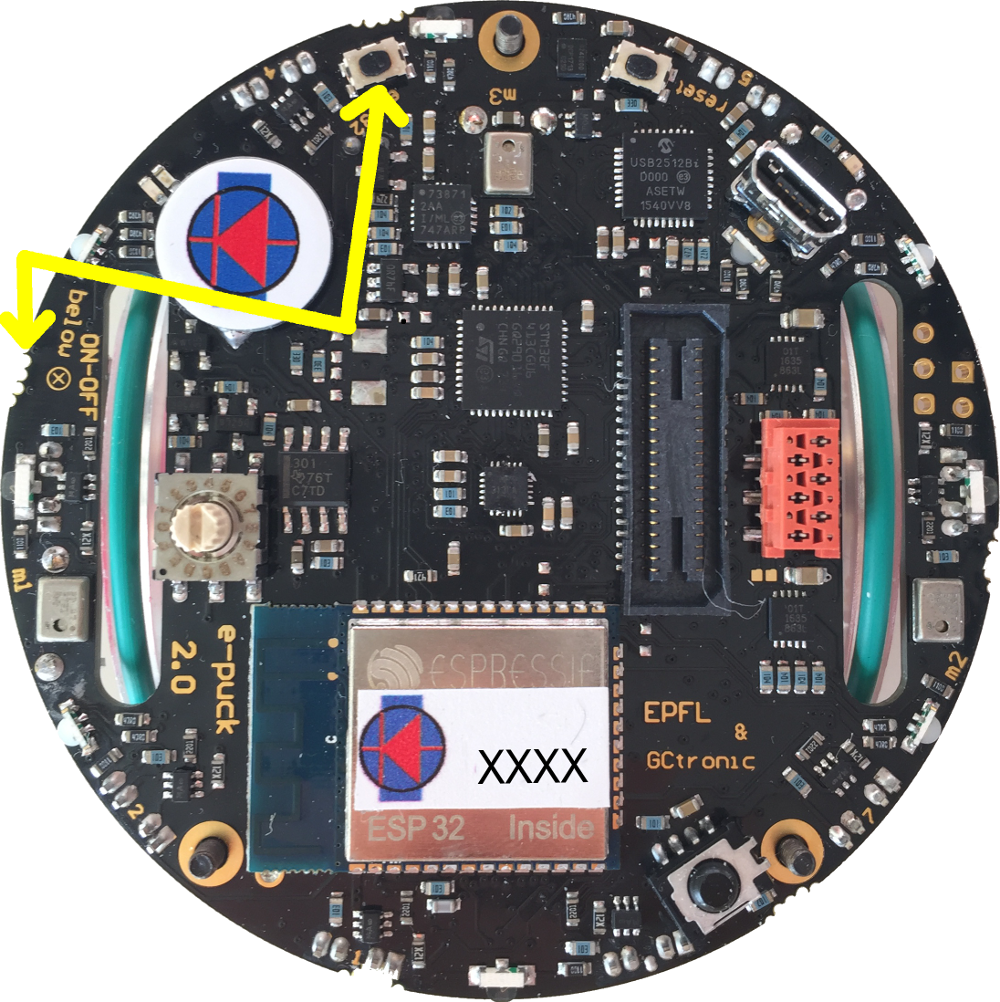
Then it will be discoverable and you will be able to pair with it.
Note that a prompt could ask you to confirm that the number written on the screen is the same on the e-puck. just ignore this and accept. Otherwise if you are asked for a pin insert 0000.
Windows 7
When you pair your computer with the e-puck2, 3 COM ports will be automatically created.
To see which COM port corresponds to which channel you need to open the properties of the paired e-puck2 robot from Bluetooth devices. Then the ports and related channels are listed in the Services tab, as shown in the following figure:
Windows 10
When you pair your computer with the e-puck2, 6 COM ports will be automatically created. The three ports you will use have Outgoing direction and are named e_puck2_xxxxx-GDB, e_puck2_xxxxx-UART, e_puck2_xxxxx-SPI. xxxxx is the ID number of your e-puck2.
To see which COM port corresponds to which channel you need to:
- open the Bluetooth devices manager
- pair with the robot
- click on
More Bluetooth options - the ports and related channels are listed in the
COM Portstab, as shown in the following figure:
Linux
Once paired with the Bluetooth manager, you need to create the port for communicating with the robot by issueing the command:
sudo rfcomm bind /dev/rfcomm0 MAC_ADDR 2
The MAC address is visible from the Bluetooth manager. The parameter 2 indicates the channel, in this case a port for the UART channel is created. If you want to connect to another service you need to change this parameter accordingly (e.g. 1 for GDB and 3 for SPI). Now you can use /dev/rfcomm0 to connect to the robot.
Mac
When you pair your computer with the e-puck2, 3 COM ports will be automatically created: /dev/cu.e-puck2_xxxxx-GDB, /dev/cu.e-puck2_xxxxx-UART and /dev/cu.e-puck2_xxxxx-SPI. xxxxx is the ID number of your e-puck2.
Testing the Bluetooth connection
You need to download the PC application provided in section PC interface: available executables.
In the connection textfield you need to enter the UART channel port, for example:
- Windows 7:
COM258 - Windows 10:
e_puck2_xxxxx-UART - Linux:
/dev/rfcomm0 - Mac:
/dev/cu.e-puck2_xxxxx-UART
and then click Connect.
You should start receiving sensors data and you can send commands to the robot.
Alternatively you can also use a simple terminal program (e.g. realterm in Windows) instead of the PC application, then you can issue manually the commands to receive sensors data or for setting the actuators (once connected, type h + ENTER for a list of availables commands).
Connecting to the WiFi
The WiFi channel is used to communicate with robot faster than with Bluetooth. At the moment a QQVGA (160x120) color image is transferred to the computer together with the sensors values at about 10 Hz; of course the robot is also able to receive commands from the computer.
In order to communicate with the robot through WiFi, first you need to configure the network parameters on the robot by connecting directly to it, since the robot is initially configured in access point mode, as explained in the following section. Once the configuration is saved on the robot, it will then connect automatically to the network and you can connect to it.
The LED2 is used to indicate the state of the WiFi connection:
- red indicates that the robot is in access point mode (waiting for configuration)
- green indicates that the robot is connected to a network and has received an IP address
- blue (toggling) indicates that the robot is transferring the image to the computer
- off when the robot cannot connect to the saved configuration
Network configuration
If there is no WiFi configuration saved in flash, then the robot will be in access point mode in order to let the user connect to it and setup a WiFi connection. The LED2 is red.
The access point SSID will be e-puck2_0XXXX where XXXX is the id of the robot; the password to connect to the access point is e-puck2robot.
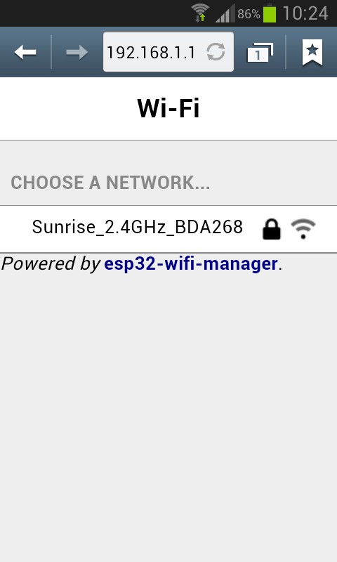
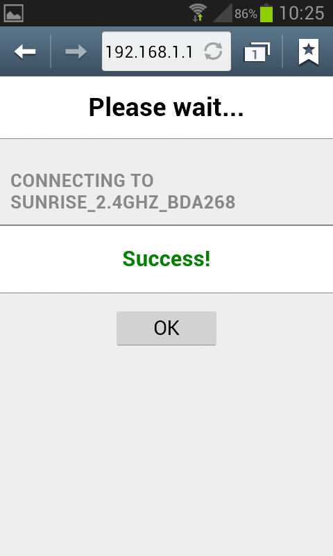
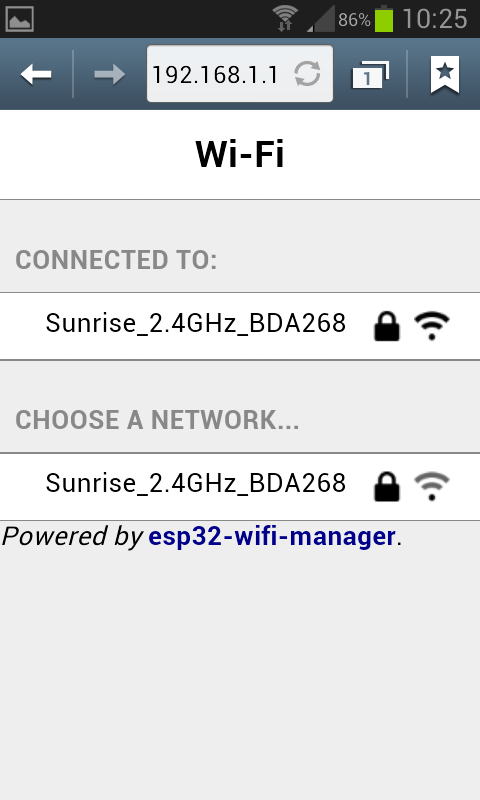
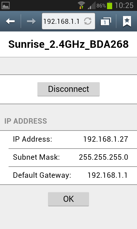
You can use a phone, a tablet or a computer to connect to the robot's WiFi and then you need to open a browser and insert the address 192.168.1.1. The available networks are scanned automatically and listed in the browser page as shown in figure 1. Choose the WiFi signal you want the robot to establish a conection with from the web generated list, and enter the related password; if the password is correct you'll get a message saying that the connection is established as shown in figure 2. After pressing OK you will be redirected to the main page showing the network to which you're connected and the others available nearby as shown in figure 3. If you press on the connected network, then you can see your IP address as shown in figure 4; take note of the address since it will be needed later.
| [1] | [2] | [3] | [4] |
 |
 |
 |
 |
Now the configuration is saved in flash, this means that when the robot is turned on it will read this configuration and try to establish a connection automatically.
Remember that you need to power cycle the robot at least once for the new configuration to be active.
Once the connection is established, the LED2 will be green.
In order to reset the current configuration you need to press the user button for 2 seconds (the LED2 red will turn on), then you need to power cycle the robot to enter access point mode.
Finding the IP address
Often the IP address assigned to the robot will remain the same when connecting to the same network, so if you took note of the IP address in section Network configuration you're ready to go to the next section.
Otherwise you need to connect the robot to the computer with the USB cable, open a terminal and connect to the port labeled Serial Monitor (see chapter Finding the USB serial ports used). Then power cycle the robot and the IP address will be shown in the terminal (together with others informations), as illustrated in the following figure:
Testing the WiFi connection
A dedicated WiFi version of the PC application was developed to communicate with the robot through TCP protocol. You can download the executable from one of the following links:
- Windows executable - WiFi
- Mac (not available yet)
- Linux (not available yet)
If you are interested to the source code, you can download it with the command git clone -b wifi --recursive https://github.com/e-puck2/monitor.git
Run the PC application, insert the IP address of the robot in the connection textfield and then click on the Connect button. You should start receiving sensors data and you can send commands to the robot. The LED2 blue will toggle.
Communication protocol
This section is the hardest part to understand. It outlines all the details about the communication protocols that you'll need to implement in order to communicate with the robot form the computer. So spend a bit of time reading and re-reading this section in order to grasp completely all the details.
Bluetooth and USB
The communication protocol is based on the advanced sercom protocol, used with the e-puck1.x robot. The advanced sercom v2 includes all the commands available in the advanced sercom protocol and add some additional commands to handle the new features of the e-puck2 robot. In particular here are the new commands:
| Command | Description | Return value / set value |
|---|---|---|
0x08
|
Get all sensors | see section Communication protocol: WiFi |
0x09
|
Set all actuators | see section Communication protocol: WiFi |
0x0A
|
Set RGB LEDs | [LED2_red][LED2_blue][LED2_green][LED4_red][LED4_blue][LED4_green][LED6_red][LED6_blue][LED6_green][LED8_red][LED8_blue][LED8_green]
|
0x0B
|
Get button state: 0 = not pressed, 1 = pressed | [STATE]
|
0x0C
|
Get all 4 microphones volumes | [MIC0_LSB][MIC0_MSB][MIC1_LSB][MIC1_MSB][MIC2_LSB][MIC2_MSB][MIC3_LSB][MIC3_MSB]
|
0x0D
|
Get distance from ToF sensor (millimeters) | [DIST_LSB][DIST_MSB]
|
0x0E
|
Get SD state: 0 = micro sd not connected, 1 = micro sd connected | [STATE]
|
WiFi
The communication is based on TCP; the robot create a TCP server and wait for a connection.
Each packet is identified by an ID (1 byte). The following IDs are used to send data from the robot to the computer:
- 0x00 = reserved
- 0x01 = QQVGA color image packet (only the first segment includes this id); packet size (without id) = 38400 bytes; image format = RGB565
- 0x02 = sensors packet; packet size (without id) = 104 bytes; the format of the returned values are based on the advanced sercom protocol and are compatible with e-puck1.x:

- Acc: raw axes values, between -1500 and 1500, resolution is +-2g
- Acceleration: acceleration magnitude
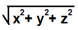 , between 0.0 and about 2600.0 (~3.46 g)
 - Orientation: between 0.0 and 360.0 degrees
0.0 deg 90.0 deg 180 deg 270 deg 


- Inclination: between 0.0 and 90.0 degrees (when tilted in any direction)
0.0 deg 90.0 deg 
- Gyro: raw axes values, between -32768 and 32767, range is +-250dps
- Magnetometer: raw axes values, between -32760 and 32760, range is +-4912 uT (magnetic flux density expressed in micro Tesla)
- Temp: temperature given in Celsius degrees
- IR proximity: between 0 (no objects detected) and 4095 (object near the sensor)
- IR ambient: between 0 (strong light) and 4095 (dark)
- ToF distance: distance given in millimeters
- Mic volume: between 0 and 4095
- Motors steps: 1000 steps per wheel revolution
- Battery:
- uSD state: 1 if the micro sd is present and can be read/write, 0 otherwise
- TV remote data: RC5 protocol
- Selector position: between 0 and 15
- Ground proximity: between 0 (no surface at all or not reflective surface e.g. black) and 1023 (very reflective surface e.g. white)
- Ground ambient: between 0 (strong light) and 1023 (dark)
- Button state: 1 button pressed, 0 button released
- Inclination: between 0.0 and 90.0 degrees (when tilted in any direction)
- 0x03 = empty packet (only id is sent); this is used as an acknowledgment for the commands packet when no sensors and no image is requested
The following IDs are used to send data from the computer to the robot:
- 0x80 = commands packet; packet size (without id) = 20 bytes:
- request:
- bit0: 0=stop image stream; 1=start image stream
- bit1: 0=stop sensors stream; 1=start sensors stream
- settings:
- bit0: 1=calibrate IR proximity sensors
- bit1: 0=disable onboard obstacle avoidance; 1=enable onboard obstacle avoidance (not implemented yet)
- bit2: 0=set motors speed; 1=set motors steps (position)
- left and right: when bit2 of
settingsfield is0, then this is the desired motors speed (-1000..1000); when1then this is the value that will be set as motors position (steps) - LEDs: 0=off; 1=on; 2=toggle
- bit0: 0=LED1 off; 1=LED1 on
- bit1: 0=LED3 off; 1=LED3 on
- bit2: 0=LED5 off; 1=LED5 on
- bit3: 0=LED7 off; 1=LED7 on
- bit4: 0=body LED off; 1=body LED on
- bit5: 0=front LED off; 1=front LED on
- RGB LEDs: for each LED, it is specified in sequence the value of red, green and blue (0...100)
- sound id: 0x01=MARIO, 0x02=UNDERWOLRD, 0x04=STARWARS, 0x08=4KHz, 0x10=10KHz, 0x20=stop sound
- request:
For example to receive the camera image (stream) the following steps need to be followed:
1) connect to the robot through TCP
2) send the command packet:
0x80 0x01 0x00 0x00 0x00 0x00 0x00 0x00 0x00 0x00 0x00 0x00 0x00 0x00 0x00 0x00 0x00 0x00 0x00 0x00 0x00
3) read the ID (1 byte) and the QQVGA color image pakcet (38400 bytes)
4) go to step 3
Webots
TBD
ROS
TBD