e-puck2 and e-puck2 robot side development: Difference between pages
| Line 1: | Line 1: | ||
[{{fullurl:e-puck2}} e-puck2 main wiki]<br/> | |||
=Installation of the e-puck2 environment= | |||
<code>Eclipse_e-puck2</code> is a distribution of Eclipse IDE for C/C++ Developers specially modified to edit and compile e-puck2's projects out of the box. It doesn't require to be installed and everything needed is located in the package given. The only dependency needed to be able to run Eclipse is '''Java'''. | |||
==Installation for Windows== | |||
< | ===Java 8 32bits=== | ||
This section can be ignored if Java version >= 8 32bits is already installed on your computer.<br> | |||
To verify you already installed Java, you can open <code>Programs and Features</code> from the <code>control panel</code> and search for a <code>Java 8 Update xxx</code> install. If this entry isn't present, then you need to install it: | |||
#Go to the [https://www.java.com/en/download/manual.jsp Java download page] and download the <code>Windows offline</code> pacakge. This is the 32bits version of Java. | |||
#Run the downloaded installer and follow its instructions to proceed with the installation of Java 32bits. | |||
#Close the internet browser if it opened at the end of the installation. | |||
:<span class="plain links">[http://projects.gctronic.com/epuck2/wiki_images/Java_windows.png <img width=500 src="http://projects.gctronic.com/epuck2/wiki_images/Java_windows.png">]</span><br/> | |||
<span class=" | :''Java download page'' | ||
== | ===Eclipse_e-puck2=== | ||
#Download the [http://projects.gctronic.com/epuck2/Eclipse_e-puck2/Eclipse_e-puck2_Win32_11_apr_2018.zip Eclipse_e-puck2 package for windows]. | |||
#Unzip the downloaded file to the location you want (can take time). It is strongly recommended for better performance and less extraction time to use 7Zip. You can download it on http://www.7-zip.org. | |||
#You can now run the <code>Eclipse_e-puck2.exe</code> to launch Eclipse. | |||
#You can create a shortcut to <code>Eclipse_e-puck2.exe</code> and place it anywhere if you want. | |||
= | :<span class="plain links">[http://projects.gctronic.com/epuck2/wiki_images/Eclipse_e-puck2_Folder_Windows.png <img width=800 src="http://projects.gctronic.com/epuck2/wiki_images/Eclipse_e-puck2_Folder_Windows.png">]</span><br/> | ||
:''Eclipse_e-puck2 folder obtained after extraction'' | |||
'''Important things to avoid :''' | |||
:1. The path to the <code>Eclipse_e-puck2</code> folder must contain zero space. | |||
::Example : | |||
::<code>C:\epfl_stuff\Eclipse_e-puck2</code> OK | |||
::<code>C:\epfl stuff\Eclipse_e-puck2</code> NOT OK | |||
:2. You must not put <code>Eclipse_e-puck2</code> folder into <code>Program Files (x86)</code>. Otherwise the compilation when using Eclipse will not work. | |||
:3. The file’s structure in the <code>Eclipse_e-puck2</code> folder must remain the same. It means no file inside this folder must be moved to another place. | |||
===Configuring the PATH variable=== | |||
The <code>PATH</code> variable is an environment variable used to store a list of the paths to the folders containing the executables we can then run in a terminal from any path. | |||
If you want to use the <code>arm-none-eabi</code> toolchain provided inside the <code>Eclipse_e-puck2</code> package, you have to add it to the <code>PATH</code> variable to be able to call it inside a terminal window. To set the <code>PATH</code> variable you need to issue the following command: | |||
= | <code>set PATH=your_installation_path\Eclipse_e-puck2\Tools\gcc-arm-none-eabi-7-2017-q4-major-win32\bin;%PATH%</code> | ||
What is important to know is that this procedure is temporary. It applies only to the terminal window used to type it. If you open a new terminal window or close this one, you will have to set again the <code>PATH</code> variable. | |||
If you want to set the <code>PATH</code> variable permanently, then go to <code>Control panel</code> => <code>System</code> => <code>Advanced system settings</code> => <code>Environment variables</code>. A list of variables defined for the user is shown, double click on the <code>PATH</code> variable (from the user variables list) and add at the end <code>;your_installation_path\Eclipse_e-puck2\Tools\gcc-arm-none-eabi-7-2017-q4-major-win32\bin</code>, then click <code>OK</code> three times. | |||
Note : The <code>arm-none-eabi</code> version can differ from the one given in this example. It could be needed to adapt the path to the correct version. | |||
== | ==Installation for Linux== | ||
===Java 8=== | |||
This section can be ignored if Java is already installed on your computer.<br> | |||
To verify whether it is installed or not you can type the following command into a terminal window: <code>update-java-alternatives -l</code>. If Java is installed, you will get some information about it, otherwise the command will be unknown.<br> | |||
You need to have <code>Java 1.8.xxxx</code> listed to be able to run <code>Eclipse_e-puck2</code>. | |||
: | Type the following commands in a terminal session to install Java SDK: | ||
<pre>sudo add-apt-repository ppa:openjdk-r/ppa | |||
sudo apt-get update | |||
sudo apt-get install openjdk-8-jre </pre> | |||
===Eclipse_e-puck2=== | |||
#Install <code>make</code> (probably you already have it installed) by issueing the command: <code>sudo apt-get install make</code> | |||
#Download the Eclipse_e-puck2 package for Linux [http://projects.gctronic.com/epuck2/Eclipse_e-puck2/Eclipse_e-puck2_Linux_11_apr_2018_32bits.tar.gz 32bits] / [http://projects.gctronic.com/epuck2//Eclipse_e-puck2/Eclipse_e-puck2_Linux_11_apr_2018_64bits.tar.gz 64bits]. Pay attention to the 32bits or 64bits version. If unsure which Linux version you have, enter the following comand <code>uname -a</code> in the terminal window and look for <code>i686</code> (32bit) or <code>x86_64</code> (64 bit). | |||
#Extract the downloaded file to the location you want (can take time): <code>tar -zxvf package_name.tar.gz</code> | |||
#You can now run the <code>Eclipse_e-puck2</code> executable to launch Eclipse. | |||
:<span class="plain links">[http://projects.gctronic.com/epuck2/wiki_images/Eclipse_e-puck2_Folder_Linux.png <img width=800 src="http://projects.gctronic.com/epuck2/wiki_images/Eclipse_e-puck2_Folder_Linux.png">]</span><br/> | |||
:''Eclipse_e-puck2 folder obtained after extraction'' | |||
The | Note : The icon of the <code>Eclipse_e-puck2</code> executable will appear after the first launch of the program. | ||
'''Important things to avoid :''' | |||
:1. You cannot create a Link to the <code>Eclipse_e-puck2</code> executable because otherwise the program will think its location is where the Link is and it will not find the resources located in the <code>Eclipse_e-puck2</code> folder. | |||
::< | :2. The path to the <code>Eclipse_e-puck2</code> folder must contain zero space. | ||
::Example : | |||
::<code>/home/student/epfl_stuff/Eclipse_e-puck2</code> OK | |||
::<code>/home/student/epfl stuff/Eclipse_e-puck2</code> NOT OK | |||
:3. The file’s structure in the <code>Eclipse_e-puck2</code> folder must remain the same. It means no file inside this folder must be moved to another place. | |||
== | ===Configuring the PATH variable=== | ||
The | The <code>PATH</code> variable is an environment variable used to store a list of the paths to the folders containing the executables we can then run in a terminal from any path. | ||
If you want to use the <code>arm-none-eabi</code> toolchain provided inside the <code>Eclipse_e-puck2</code> package, you have to add it to the <code>PATH</code> variable to be able to call it inside a terminal window. To set the <code>PATH</code> variable you need to issue the following command: | |||
<code>export PATH=your_installation_path/Eclipse_e-puck2/Tools/gcc-arm-none-eabi-7-2017-q4-major/bin:$PATH</code> | |||
What is important to know is that this procedure is temporary. It applies only to the terminal window used to type it. If you open a new terminal window or close this one, you will have to set again the <code>PATH</code> variable. | |||
If you want to set the <code>PATH</code> variable permanently, then you need to set it in the <code>.profile</code> file by issuing the command:<br> | |||
<code>echo 'export PATH=your_installation_path/Eclipse_e-puck2/Tools/gcc-arm-none-eabi-7-2017-q4-major/bin:$PATH' >> ~/.profile</code><br> | |||
Close and reopen the terminal before using your newly set environment variable. | |||
Note : The <code>arm-none-eabi</code> version can differ from the one given in this example. It could be needed to adapt the path to the correct version. | |||
==Installation for Mac== | |||
=== | ===Command Line Tools === | ||
To compile on Mac with <code>Eclipse_e-puck2</code>, it is necessary to have the <code>Command Line Tools</code> installed. It is a bundle of many commonly used tools.<br> | |||
You can install it by typing the following command in a terminal window: <code>xcode-select --install</code>. It will then open a popup asking you if you want to install this bundle. Otherwise it will tell you it is already installed. | |||
=== | ===Java 8=== | ||
This section can be ignored if Java is already installed on your computer.<br> | |||
To verify whether it is installed or not you can type the following command into a terminal window. It will list all the Java runtimes installed on your Mac: <code>/usr/libexec/java_home -V</code><br> | |||
You need to have <code>Java SE 8</code> listed to be able to run <code>Eclipse_e-puck2</code>. | |||
:1. Go to the [http://www.oracle.com/technetwork/java/javase/downloads/jdk8-downloads-2133151.html Java download page] and download the <code>Mac OS X Java 8 SE Development Kit</code>. It is the <code>.dmg</code> file without the Demos and Samples. | |||
:1. | ::For example: <code>jdk-8uXXX-macosx-x64.dmg</code> | ||
:2. | :2. Open the <code>.dmg</code> file downloaded, run the installer and follow the instructions to proceed with the installation of Java SDK. | ||
:<span class="plain links">[http://projects.gctronic.com/epuck2/wiki_images/Java_mac.png <img width=500 src="http://projects.gctronic.com/epuck2/wiki_images/Java_mac.png">]</span><br/> | |||
:''Java download page'' | |||
== | ===Eclipse_e-puck2=== | ||
:1. Download the [http://projects.gctronic.com/epuck2/Eclipse_e-puck2/Eclipse_e-puck2_Mac_11_apr_2018.dmg Eclipse_e-puck2 package for Mac]. | |||
:2. Open the <code>.dmg</code> file downloaded (confirm opening if a warning message appear) and ''drag and drop'' the <code>Eclipse_e-puck2.app</code> into the <code>Applications</code> folder | |||
::Note: you can place the <code>Eclipse_e-puck2.app</code> anywhere, as long as the full path to it doesn’t contain any space, if you don’t want it to be in <code>Applications</code>. | |||
:3. You can create an Alias to <code>Eclipse_e-puck2.app</code> and place it anywhere if you want. | |||
===First launch and Gatekeeper=== | |||
It’s very likely that <code>Gatekeeper</code> (one of the protections of Mac OS) will prevent you to launch <code>Eclipse_e-puck2.app</code> because it isn’t signed from a known developer.<br> | |||
If you can’t run the program because of a warning of the system, press <code>OK</code> and try to launch it by right clicking on it and choosing <code>open</code> in the contextual menu (may be slow to open the first time).<br> | |||
If <code>Unable to open "Eclipse_e-puck2.app" because this app comes from an unidentified developer.</code> or if <code>"Eclipse.app" is corrupted and cannot be opened. You should place this item in the Trash.</code> appears after executing the app the first time, it is needed to disable temporarily <code>Gatekeeper</code>. | |||
To do so : | |||
:1. Go to <code>System Preferences->security and privacy->General</code> and authorize downloaded application from <code>Anywhere</code>. | |||
== | ::<span class="plain links">[http://projects.gctronic.com/epuck2/wiki_images/security_tab_mac.png <img width=500 src="http://projects.gctronic.com/epuck2/wiki_images/security_tab_mac.png">]</span><br/> | ||
::''Security settings of Mac OS'' | |||
::If you are on Mac OS Sierra or greater (greater or equal to Mac OS 10.12), you must type the following command on the terminal to make the option above appear. | |||
::<code>sudo spctl --master-disable</code> | |||
:2. Now you can try to run the application and it should work. | |||
:3. If Eclipse opened successfully, it is time to reactivate <code>Gatekeeper</code>. Simply set back the setting of <code>Gatekeeper</code>. | |||
::For the ones who needed to type a command to disable <code>Gatekeeper</code>, here is the command to reactivate it. | |||
::<code>sudo spctl --master-enable</code> | |||
This procedure is only needed the first time. After that <code>Gatekeeper</code> will remember your choice to let run this application and will not bother you anymore, as long as you use this application. If you re-download it, you will have to redo the procedure for <code>Gatekeeper</code>. | |||
'''Important things to avoid :''' | |||
:1. The path to the <code>Eclipse_e-puck2.app</code> must contain zero space. | |||
::Example : | |||
::<code>/home/student/epfl_stuff/Eclipse_e-puck2</code> OK | |||
::<code>/home/student/epfl stuff/Eclipse_e-puck2</code> NOT OK | |||
:2. The file’s structure in the <code>Eclipse_e-puck2.app</code> must remain the same. It means no file inside this app must be moved to another place. | |||
===Configuring the PATH variable=== | |||
The <code>PATH</code> variable is an environment variable used to store a list of the paths to the folders containing the executables we can then run in a terminal from any path. | |||
If you want to use the <code>arm-none-eabi</code> toolchain provided inside the <code>Eclipse_e-puck2</code> package, you have to add it to the <code>PATH</code> variable to be able to call it inside a terminal window. To set the <code>PATH</code> variable you need to issue the following command: | |||
<code> | |||
<code> | |||
<code>export PATH=your_installation_path/Eclipse_e-puck2.app/Contents/Eclipse_e-puck2/Tools/gcc-arm-none-eabi-7-2017-q4-major/bin:$PATH</code> | |||
If you put the <code>Eclipse_e-puck2.app</code> into the <code>Applications</code> folder then the exact command would be: | |||
<code>export PATH=/Applications/Eclipse_e-puck2.app/Contents/Eclipse_e-puck2/Tools/gcc-arm-none-eabi-7-2017-q4-major/bin:$PATH</code> | |||
What is important to know is that this procedure is temporary. It applies only to the terminal window used to type it. If you open a new terminal window or close this one, you will have to set again the <code>PATH</code> variable. | |||
If you want to set the <code>PATH</code> variable permanently, then you need to set it in the <code>.bash_profile</code> file by issuing the command:<br> | |||
<code>echo 'export PATH=your_installation_path/Eclipse_e-puck2.app/Contents/Eclipse_e-puck2/Tools/gcc-arm-none-eabi-7-2017-q4-major/bin:$PATH' >> ~/.bash_profile</code><br> | |||
Close and reopen the terminal before using your newly set environment variable. | |||
Note : The <code>arm-none-eabi</code> version can differ from the one given in this example. It could be needed to adapt the path to the correct version. | |||
The | |||
=Get the source code= | |||
The code of the e-puck2 is open source and is available as a git repository. To download the source code you need to install git on your system: | |||
* Windows: downlaod git from [https://gitforwindows.org/ https://gitforwindows.org/] and follow the installation instructions (default configuration is ok) | |||
* Linux: issue the command <code>sudo apt-get install git</code> | |||
* Mac: issue the command <code>brew install git</code> | |||
The source code can downloaded with the command: <code>git clone --recursive https://github.com/e-puck2/e-puck2_main-processor.git</code><br/> | |||
The command must be issued in <code>Git bash</code> on Windows, or in a terminal on Linux / Mac. | |||
This repository contains the main microcontroller standard firmware together with the e-puck2 library. This library includes all the functions needed to interact with the robot's sensors and actuators; the factory firmware shows how to use these functions.<br/> | |||
A snapshot of the repository can be donwloaded from [http://projects.gctronic.com/epuck2/e-puck2_main-processor_snapshot_16.02.18_13fa922.zip e-puck2_main-processor_snapshot_16.02.18.zip].<br/> | |||
=Creating a project= | |||
==Main microcontroller standard firmware project== | |||
If you want to modify the code of the standard firmware running on the main microcontroller, or if you want to have a look at the implementation details, then you can add this project in Eclipse by following the next steps:<br/> | |||
# Run Eclipse and then select <code>File->New->Makefile Project with Existing Code</code>. | |||
# Next click on the <code>Browse</code> button and choose the project folder of the git repository downloaded previously (should be named <code>e-puck2_main-processor</code>) and set a project name (otherwise you can keep the one created by Eclipse). Choose <code>None</code> for the the toolchain. | |||
# Click on the <code>Finish</code> button and the project is added to Eclipse. | |||
# Build the project by selecting one directory of the project from the left panel and then <code>Project->Build Project</code>. | |||
== | ==Project template== | ||
The | The main microcontroller standard firmware project can also be used as a library to build your own project on top of it.<br> | ||
To accomplish that, you have to copy the folder <code>Project_template</code>, contained in the <code>e-puck2_main-processor</code> project, and place it in the same directory of the <code>e-puck2_main-processor</code> project; you can of course rename the folder to the name you want (e.g. <code>myproject</code>). You must end up with the following directory tree:<br> | |||
* e-puck2 | |||
** e-puck2_main-processor | |||
** myproject | |||
Then you can add this project in Eclipse by following the next steps: | |||
< | # Run Eclipse and then select <code>File->New->Makefile Project with Existing Code</code>. | ||
# Next click on the <code>Browse</code> button and choose the project folder of your project (e.g. <code>myproject</code>) and set a project name (otherwise you can keep the one created by Eclipse). Choose <code>None</code> for the the toolchain. | |||
< | # Click on the <code>Finish</code> button and the project is added to Eclipse. | ||
# Select the project root folder and go to <code>Project->Properties->C/C++ General->Preprocessor Include Paths, Macros etc->Providers</code> and check <code>CDT Cross GCC Built-in Compiler Settings</code>.<br> Then in the textbox below, write <code>arm-none-eabi-gcc ${FLAGS} -E -P -v -dD "${INPUTS}"</code>. | |||
# Create a linked folder inside your project that links to the <code>e-puck2_main-processor</code> library. This allows Eclipse to index the declarations and implementations of the functions and variables in the code of the library. | |||
##Select the project root folder and go to <code>File->New->Folder</code>. | |||
##Check <code>Advanced >></code> on the bottom. | |||
##Choose <code>Link to alternate location (Linked Folder)</code>. | |||
##Type <code>PROJECT_LOC/../e-puck2_main-processor</code> and click the <code>Finish</code> button. | |||
# Build the project by selecting one file of the project from the left panel and then <code>Project->Build Project</code>. The result of the compilation will appear in the <code>build</code> folder in your project folder. | |||
# After you compile the project, select the project root folder and go to <code>Project->C/C++ Index->Rebuild</code> to rebuild the index (we need to have compiled at least one time in order to let Eclipse find all the paths to the files used). | |||
Now you can write your own program. If you want to add source files (<code>.c</code>) to the project you need to add them also in the <code>makefile</code>, in the <code>CSRC</code> definition. All the headers files (<code>.h</code>) located next to the <code>makefile</code> are automatically included in the compilation, but if you need to place them into folders, you have to specify these folders in the <code>makefile</code>, in the <code>INCDIR</code> definition. The same is needed for any desired <code>.h</code> files from other external folders.<br/> | |||
< | In the <code>makefile</code> you can also set the name of your project.<br/> | ||
< | This <code>makefile</code> uses the main makefile of the <code>e-puck2_main-processor</code> project. This means you can add custom commands to the <code>makefile</code> but it should not interfere with the main makefile. | ||
= | =Configuring the Debugger's settings= | ||
<code>Eclipse_e-puck2</code> contains everything needed to compile, program and debug the e-puck2.<br> | |||
The only settings to configure with a new project are located under the <code>Debug Configurations</code> tab of Eclipse (you can also find it on <code>Run->Debug Configurations</code>). | |||
:<span class="plain links">[http://projects.gctronic.com/epuck2/wiki_images/Debug_configuration.png <img width=231 src="http://projects.gctronic.com/epuck2/wiki_images/Debug_configuration.png">]</span><br/> | |||
Once in the settings, select <code>Generic Blackmagic Probe</code> preset on the left panel. Then you need to configure two things : | |||
= | # In the <code>main</code> tab, select which project to debug and the path to the compiled file. If the project has already been compiled, Eclipse should have indexed the binaries and you can list the project and the compiled files using respectively the <code>Browse...</code> and <code>Search Project...</code> buttons.<br/> If there is nothing apering when you press <code>Search Project...</code> then you must enter the <code>.elf</code> file name by hand, which can be found in your project <code>build</code> folder (e.g. <code>build/e-puck2_main-processor.elf</code>). | ||
# In the <code>Startup</code> tab, you need to replace the serial port name written on the first line of the text box by the one used by the GDB Server of your robot. [http://www.gctronic.com/doc/index.php?title=e-puck2#Finding_the_USB_serial_ports_used See how to find it]. | |||
:* For Windows, it will be <code>\\.\COMX</code>, <code>X</code> being the port number. | |||
:* For Linux, it will be <code>/dev/ttyACMX</code>, <code>X</code> being the port number | |||
:* For Mac, it will be <code>/dev/cu.usbmodemXXXXX</code>, <code>XXXXX</code> being the port number. | |||
:* You can also type <code>${COM_PORT}</code> instead of the com port in order to use the variable <code>COM_PORT</code> for the debug configuration.<br>To change the value of this variable, go to the <code>main</code> tab again, click on the <code>Variables...</code> button and click on the <code>Edit Variables...</code> button. The opened window will let you edit the value of the variable.<br>Using the variable <code>COM_PORT</code> instead of the real com port in a debug configuration is useful if for example you have multiple debug configurations. If for some reason you need to change the serial port to use, then you can simply edit the variable <code>COM_PORT</code> instead of editing the serial port for each debug configuration. | |||
If you want to debug another project, you can duplicate this settings and change the relevant parts (project name and path to compiled file) in order to have one launch configuration for each project.<br/> | |||
:<span class="plain links">[http://projects.gctronic.com/epuck2/wiki_images/e-puck2-debug.jpg <img width=400 src="http://projects.gctronic.com/epuck2/wiki_images/e-puck2-debug-small.jpg">]</span><br/> | |||
Now you should be able to use the debugger with Eclipse. | |||
=Running a debugging session= | |||
Once the debugger is configured, you can start a debugging session. When starting a session, the robot is programmed with the current developed program, thus starting a debugging session means also updating the main microcontroller firmware. This is in fact the way to update the firwmare via Eclipse; to do it manually refer to the section [http://www.gctronic.com/doc/index.php?title=e-puck2#Firmware_update Main microcontroller: firmware update]. | |||
To start a session follow the next steps: | |||
# Connect the robot to the computer and turn it on | |||
# From Eclipse, launch the debug configuration previously set: from the menu <code>Run->Debug configurations...</code>, select the configuration and click on the <code>Debug</code> button.<br>Alternatively you can directly select your configuration from the debugger drop-down menu.<br><span class="plain links">[http://projects.gctronic.com/epuck2/wiki_images/e-puck2-debug2.png <img width=350 src="http://projects.gctronic.com/epuck2/wiki_images/e-puck2-debug2.png">]</span><br/> | |||
# When the debugging session is started, Eclipse will change the view to the <code>Debug perspective</code>. Right-click on the main process and select <code>Restart</code> to restart the program from the beginning<br><span class="plain links">[http://projects.gctronic.com/epuck2/wiki_images/e-puck2-debug3.png <img width=500 src="http://projects.gctronic.com/epuck2/wiki_images/e-puck2-debug3-small.png">]</span> | |||
# Click on the <code>Resume</code> button on top of the window to start your program. Now you can suspend and resume whenever you want, then when you want to modify your code again you click on the <code>Terminate</code> button and click on the <code>C/C++ perspective</code> button.<br><span class="plain links">[http://projects.gctronic.com/epuck2/wiki_images/e-puck2-debug4.png <img width=500 src="http://projects.gctronic.com/epuck2/wiki_images/e-puck2-debug4-small.png">]</span> | |||
==Adding breakpoints== | |||
=== | ==Watch variables== | ||
=== | ==Analyze microcontroller registers content== | ||
Revision as of 11:52, 8 August 2018
Installation of the e-puck2 environment
Eclipse_e-puck2 is a distribution of Eclipse IDE for C/C++ Developers specially modified to edit and compile e-puck2's projects out of the box. It doesn't require to be installed and everything needed is located in the package given. The only dependency needed to be able to run Eclipse is Java.
Installation for Windows
Java 8 32bits
This section can be ignored if Java version >= 8 32bits is already installed on your computer.
To verify you already installed Java, you can open Programs and Features from the control panel and search for a Java 8 Update xxx install. If this entry isn't present, then you need to install it:
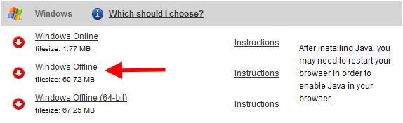
- Go to the Java download page and download the
Windows offlinepacakge. This is the 32bits version of Java. - Run the downloaded installer and follow its instructions to proceed with the installation of Java 32bits.
- Close the internet browser if it opened at the end of the installation.
- Java download page
Eclipse_e-puck2
- Download the Eclipse_e-puck2 package for windows.
- Unzip the downloaded file to the location you want (can take time). It is strongly recommended for better performance and less extraction time to use 7Zip. You can download it on http://www.7-zip.org.
- You can now run the
Eclipse_e-puck2.exeto launch Eclipse. - You can create a shortcut to
Eclipse_e-puck2.exeand place it anywhere if you want.
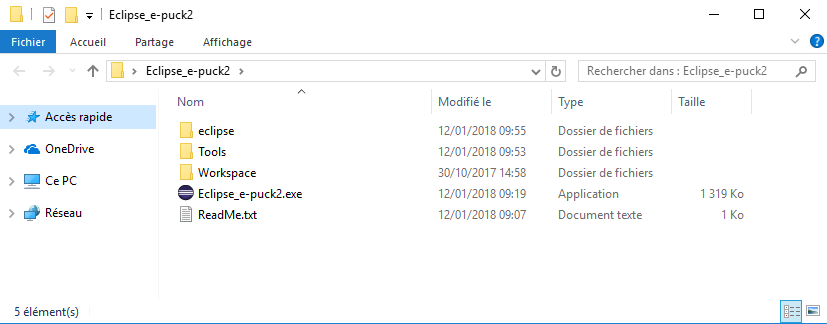
- Eclipse_e-puck2 folder obtained after extraction
Important things to avoid :
- 1. The path to the
Eclipse_e-puck2folder must contain zero space.- Example :
C:\epfl_stuff\Eclipse_e-puck2OKC:\epfl stuff\Eclipse_e-puck2NOT OK
- 2. You must not put
Eclipse_e-puck2folder intoProgram Files (x86). Otherwise the compilation when using Eclipse will not work. - 3. The file’s structure in the
Eclipse_e-puck2folder must remain the same. It means no file inside this folder must be moved to another place.
Configuring the PATH variable
The PATH variable is an environment variable used to store a list of the paths to the folders containing the executables we can then run in a terminal from any path.
If you want to use the arm-none-eabi toolchain provided inside the Eclipse_e-puck2 package, you have to add it to the PATH variable to be able to call it inside a terminal window. To set the PATH variable you need to issue the following command:
set PATH=your_installation_path\Eclipse_e-puck2\Tools\gcc-arm-none-eabi-7-2017-q4-major-win32\bin;%PATH%
What is important to know is that this procedure is temporary. It applies only to the terminal window used to type it. If you open a new terminal window or close this one, you will have to set again the PATH variable.
If you want to set the PATH variable permanently, then go to Control panel => System => Advanced system settings => Environment variables. A list of variables defined for the user is shown, double click on the PATH variable (from the user variables list) and add at the end ;your_installation_path\Eclipse_e-puck2\Tools\gcc-arm-none-eabi-7-2017-q4-major-win32\bin, then click OK three times.
Note : The arm-none-eabi version can differ from the one given in this example. It could be needed to adapt the path to the correct version.
Installation for Linux
Java 8
This section can be ignored if Java is already installed on your computer.
To verify whether it is installed or not you can type the following command into a terminal window: update-java-alternatives -l. If Java is installed, you will get some information about it, otherwise the command will be unknown.
You need to have Java 1.8.xxxx listed to be able to run Eclipse_e-puck2.
Type the following commands in a terminal session to install Java SDK:
sudo add-apt-repository ppa:openjdk-r/ppa
sudo apt-get update
sudo apt-get install openjdk-8-jre
Eclipse_e-puck2
- Install
make(probably you already have it installed) by issueing the command:sudo apt-get install make - Download the Eclipse_e-puck2 package for Linux 32bits / 64bits. Pay attention to the 32bits or 64bits version. If unsure which Linux version you have, enter the following comand
uname -ain the terminal window and look fori686(32bit) orx86_64(64 bit). - Extract the downloaded file to the location you want (can take time):
tar -zxvf package_name.tar.gz - You can now run the
Eclipse_e-puck2executable to launch Eclipse.
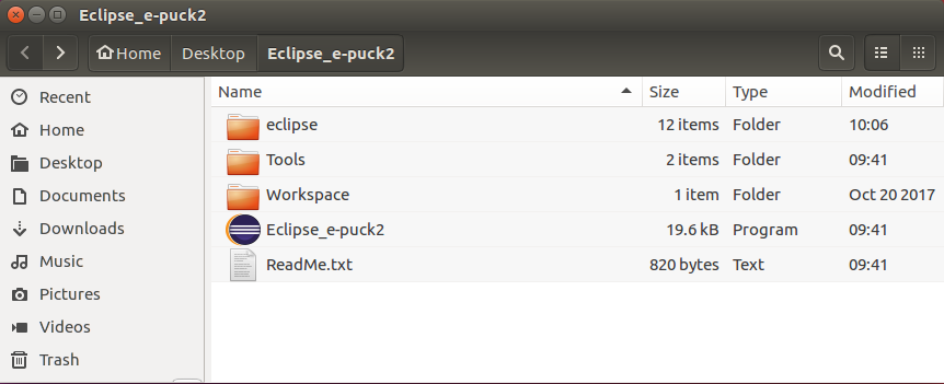
- Eclipse_e-puck2 folder obtained after extraction
Note : The icon of the Eclipse_e-puck2 executable will appear after the first launch of the program.
Important things to avoid :
- 1. You cannot create a Link to the
Eclipse_e-puck2executable because otherwise the program will think its location is where the Link is and it will not find the resources located in theEclipse_e-puck2folder. - 2. The path to the
Eclipse_e-puck2folder must contain zero space.- Example :
/home/student/epfl_stuff/Eclipse_e-puck2OK/home/student/epfl stuff/Eclipse_e-puck2NOT OK
- 3. The file’s structure in the
Eclipse_e-puck2folder must remain the same. It means no file inside this folder must be moved to another place.
Configuring the PATH variable
The PATH variable is an environment variable used to store a list of the paths to the folders containing the executables we can then run in a terminal from any path.
If you want to use the arm-none-eabi toolchain provided inside the Eclipse_e-puck2 package, you have to add it to the PATH variable to be able to call it inside a terminal window. To set the PATH variable you need to issue the following command:
export PATH=your_installation_path/Eclipse_e-puck2/Tools/gcc-arm-none-eabi-7-2017-q4-major/bin:$PATH
What is important to know is that this procedure is temporary. It applies only to the terminal window used to type it. If you open a new terminal window or close this one, you will have to set again the PATH variable.
If you want to set the PATH variable permanently, then you need to set it in the .profile file by issuing the command:
echo 'export PATH=your_installation_path/Eclipse_e-puck2/Tools/gcc-arm-none-eabi-7-2017-q4-major/bin:$PATH' >> ~/.profile
Close and reopen the terminal before using your newly set environment variable.
Note : The arm-none-eabi version can differ from the one given in this example. It could be needed to adapt the path to the correct version.
Installation for Mac
Command Line Tools
To compile on Mac with Eclipse_e-puck2, it is necessary to have the Command Line Tools installed. It is a bundle of many commonly used tools.
You can install it by typing the following command in a terminal window: xcode-select --install. It will then open a popup asking you if you want to install this bundle. Otherwise it will tell you it is already installed.
Java 8
This section can be ignored if Java is already installed on your computer.
To verify whether it is installed or not you can type the following command into a terminal window. It will list all the Java runtimes installed on your Mac: /usr/libexec/java_home -V
You need to have Java SE 8 listed to be able to run Eclipse_e-puck2.
- 1. Go to the Java download page and download the
Mac OS X Java 8 SE Development Kit. It is the.dmgfile without the Demos and Samples.- For example:
jdk-8uXXX-macosx-x64.dmg
- For example:
- 2. Open the
.dmgfile downloaded, run the installer and follow the instructions to proceed with the installation of Java SDK.
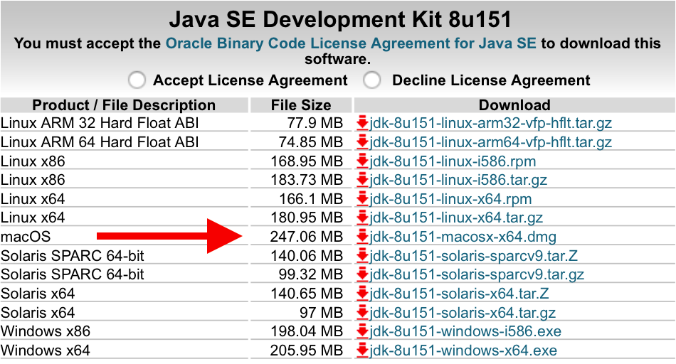
- Java download page
Eclipse_e-puck2
- 1. Download the Eclipse_e-puck2 package for Mac.
- 2. Open the
.dmgfile downloaded (confirm opening if a warning message appear) and drag and drop theEclipse_e-puck2.appinto theApplicationsfolder- Note: you can place the
Eclipse_e-puck2.appanywhere, as long as the full path to it doesn’t contain any space, if you don’t want it to be inApplications.
- Note: you can place the
- 3. You can create an Alias to
Eclipse_e-puck2.appand place it anywhere if you want.
First launch and Gatekeeper
It’s very likely that Gatekeeper (one of the protections of Mac OS) will prevent you to launch Eclipse_e-puck2.app because it isn’t signed from a known developer.
If you can’t run the program because of a warning of the system, press OK and try to launch it by right clicking on it and choosing open in the contextual menu (may be slow to open the first time).
If Unable to open "Eclipse_e-puck2.app" because this app comes from an unidentified developer. or if "Eclipse.app" is corrupted and cannot be opened. You should place this item in the Trash. appears after executing the app the first time, it is needed to disable temporarily Gatekeeper.
To do so :
- 1. Go to
System Preferences->security and privacy->Generaland authorize downloaded application fromAnywhere.
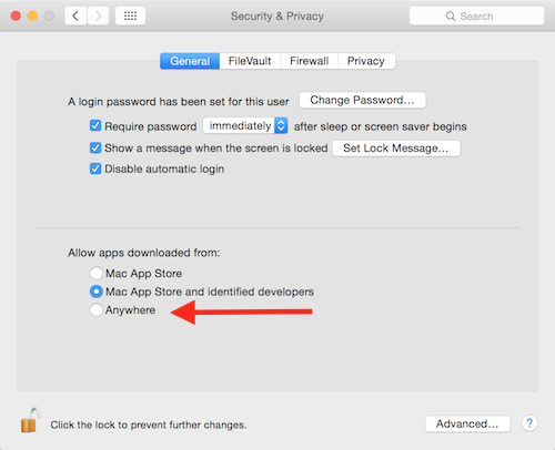
- Security settings of Mac OS
- If you are on Mac OS Sierra or greater (greater or equal to Mac OS 10.12), you must type the following command on the terminal to make the option above appear.
sudo spctl --master-disable
- 2. Now you can try to run the application and it should work.
- 3. If Eclipse opened successfully, it is time to reactivate
Gatekeeper. Simply set back the setting ofGatekeeper.- For the ones who needed to type a command to disable
Gatekeeper, here is the command to reactivate it. sudo spctl --master-enable
- For the ones who needed to type a command to disable
This procedure is only needed the first time. After that Gatekeeper will remember your choice to let run this application and will not bother you anymore, as long as you use this application. If you re-download it, you will have to redo the procedure for Gatekeeper.
Important things to avoid :
- 1. The path to the
Eclipse_e-puck2.appmust contain zero space.- Example :
/home/student/epfl_stuff/Eclipse_e-puck2OK/home/student/epfl stuff/Eclipse_e-puck2NOT OK
- 2. The file’s structure in the
Eclipse_e-puck2.appmust remain the same. It means no file inside this app must be moved to another place.
Configuring the PATH variable
The PATH variable is an environment variable used to store a list of the paths to the folders containing the executables we can then run in a terminal from any path.
If you want to use the arm-none-eabi toolchain provided inside the Eclipse_e-puck2 package, you have to add it to the PATH variable to be able to call it inside a terminal window. To set the PATH variable you need to issue the following command:
export PATH=your_installation_path/Eclipse_e-puck2.app/Contents/Eclipse_e-puck2/Tools/gcc-arm-none-eabi-7-2017-q4-major/bin:$PATH
If you put the Eclipse_e-puck2.app into the Applications folder then the exact command would be:
export PATH=/Applications/Eclipse_e-puck2.app/Contents/Eclipse_e-puck2/Tools/gcc-arm-none-eabi-7-2017-q4-major/bin:$PATH
What is important to know is that this procedure is temporary. It applies only to the terminal window used to type it. If you open a new terminal window or close this one, you will have to set again the PATH variable.
If you want to set the PATH variable permanently, then you need to set it in the .bash_profile file by issuing the command:
echo 'export PATH=your_installation_path/Eclipse_e-puck2.app/Contents/Eclipse_e-puck2/Tools/gcc-arm-none-eabi-7-2017-q4-major/bin:$PATH' >> ~/.bash_profile
Close and reopen the terminal before using your newly set environment variable.
Note : The arm-none-eabi version can differ from the one given in this example. It could be needed to adapt the path to the correct version.
Get the source code
The code of the e-puck2 is open source and is available as a git repository. To download the source code you need to install git on your system:
- Windows: downlaod git from https://gitforwindows.org/ and follow the installation instructions (default configuration is ok)
- Linux: issue the command
sudo apt-get install git - Mac: issue the command
brew install git
The source code can downloaded with the command: git clone --recursive https://github.com/e-puck2/e-puck2_main-processor.git
The command must be issued in Git bash on Windows, or in a terminal on Linux / Mac.
This repository contains the main microcontroller standard firmware together with the e-puck2 library. This library includes all the functions needed to interact with the robot's sensors and actuators; the factory firmware shows how to use these functions.
A snapshot of the repository can be donwloaded from e-puck2_main-processor_snapshot_16.02.18.zip.
Creating a project
Main microcontroller standard firmware project
If you want to modify the code of the standard firmware running on the main microcontroller, or if you want to have a look at the implementation details, then you can add this project in Eclipse by following the next steps:
- Run Eclipse and then select
File->New->Makefile Project with Existing Code. - Next click on the
Browsebutton and choose the project folder of the git repository downloaded previously (should be namede-puck2_main-processor) and set a project name (otherwise you can keep the one created by Eclipse). ChooseNonefor the the toolchain. - Click on the
Finishbutton and the project is added to Eclipse. - Build the project by selecting one directory of the project from the left panel and then
Project->Build Project.
Project template
The main microcontroller standard firmware project can also be used as a library to build your own project on top of it.
To accomplish that, you have to copy the folder Project_template, contained in the e-puck2_main-processor project, and place it in the same directory of the e-puck2_main-processor project; you can of course rename the folder to the name you want (e.g. myproject). You must end up with the following directory tree:
- e-puck2
- e-puck2_main-processor
- myproject
Then you can add this project in Eclipse by following the next steps:
- Run Eclipse and then select
File->New->Makefile Project with Existing Code. - Next click on the
Browsebutton and choose the project folder of your project (e.g.myproject) and set a project name (otherwise you can keep the one created by Eclipse). ChooseNonefor the the toolchain. - Click on the
Finishbutton and the project is added to Eclipse. - Select the project root folder and go to
Project->Properties->C/C++ General->Preprocessor Include Paths, Macros etc->Providersand checkCDT Cross GCC Built-in Compiler Settings.
Then in the textbox below, writearm-none-eabi-gcc ${FLAGS} -E -P -v -dD "${INPUTS}". - Create a linked folder inside your project that links to the
e-puck2_main-processorlibrary. This allows Eclipse to index the declarations and implementations of the functions and variables in the code of the library.- Select the project root folder and go to
File->New->Folder. - Check
Advanced >>on the bottom. - Choose
Link to alternate location (Linked Folder). - Type
PROJECT_LOC/../e-puck2_main-processorand click theFinishbutton.
- Select the project root folder and go to
- Build the project by selecting one file of the project from the left panel and then
Project->Build Project. The result of the compilation will appear in thebuildfolder in your project folder. - After you compile the project, select the project root folder and go to
Project->C/C++ Index->Rebuildto rebuild the index (we need to have compiled at least one time in order to let Eclipse find all the paths to the files used).
Now you can write your own program. If you want to add source files (.c) to the project you need to add them also in the makefile, in the CSRC definition. All the headers files (.h) located next to the makefile are automatically included in the compilation, but if you need to place them into folders, you have to specify these folders in the makefile, in the INCDIR definition. The same is needed for any desired .h files from other external folders.
In the makefile you can also set the name of your project.
This makefile uses the main makefile of the e-puck2_main-processor project. This means you can add custom commands to the makefile but it should not interfere with the main makefile.
Configuring the Debugger's settings
Eclipse_e-puck2 contains everything needed to compile, program and debug the e-puck2.
The only settings to configure with a new project are located under the Debug Configurations tab of Eclipse (you can also find it on Run->Debug Configurations).
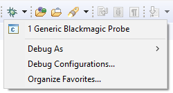
Once in the settings, select Generic Blackmagic Probe preset on the left panel. Then you need to configure two things :
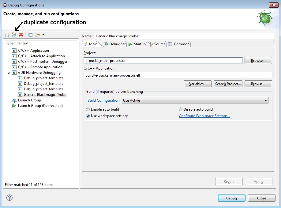
- In the
maintab, select which project to debug and the path to the compiled file. If the project has already been compiled, Eclipse should have indexed the binaries and you can list the project and the compiled files using respectively theBrowse...andSearch Project...buttons.
If there is nothing apering when you pressSearch Project...then you must enter the.elffile name by hand, which can be found in your projectbuildfolder (e.g.build/e-puck2_main-processor.elf). - In the
Startuptab, you need to replace the serial port name written on the first line of the text box by the one used by the GDB Server of your robot. See how to find it.
- For Windows, it will be
\\.\COMX,Xbeing the port number. - For Linux, it will be
/dev/ttyACMX,Xbeing the port number - For Mac, it will be
/dev/cu.usbmodemXXXXX,XXXXXbeing the port number. - You can also type
${COM_PORT}instead of the com port in order to use the variableCOM_PORTfor the debug configuration.
To change the value of this variable, go to themaintab again, click on theVariables...button and click on theEdit Variables...button. The opened window will let you edit the value of the variable.
Using the variableCOM_PORTinstead of the real com port in a debug configuration is useful if for example you have multiple debug configurations. If for some reason you need to change the serial port to use, then you can simply edit the variableCOM_PORTinstead of editing the serial port for each debug configuration.
- For Windows, it will be
If you want to debug another project, you can duplicate this settings and change the relevant parts (project name and path to compiled file) in order to have one launch configuration for each project.
Now you should be able to use the debugger with Eclipse.
Running a debugging session
Once the debugger is configured, you can start a debugging session. When starting a session, the robot is programmed with the current developed program, thus starting a debugging session means also updating the main microcontroller firmware. This is in fact the way to update the firwmare via Eclipse; to do it manually refer to the section Main microcontroller: firmware update.
To start a session follow the next steps:
- Connect the robot to the computer and turn it on
- From Eclipse, launch the debug configuration previously set: from the menu
Run->Debug configurations..., select the configuration and click on theDebugbutton.
Alternatively you can directly select your configuration from the debugger drop-down menu.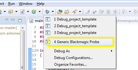
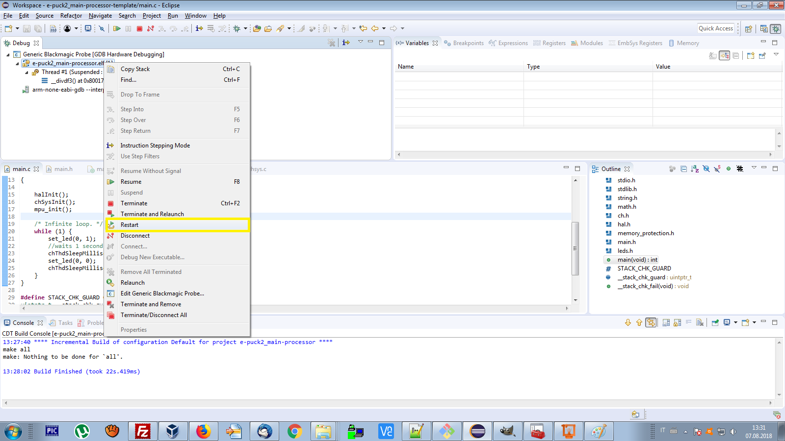
- When the debugging session is started, Eclipse will change the view to the
Debug perspective. Right-click on the main process and selectRestartto restart the program from the beginning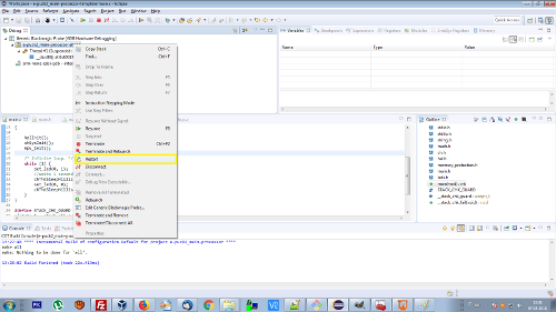
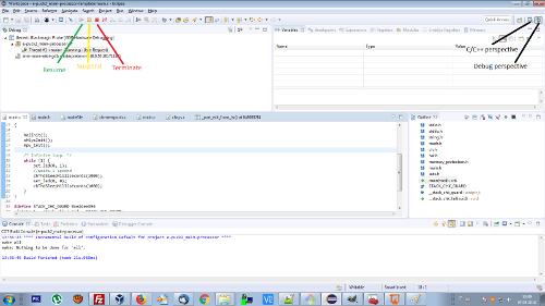
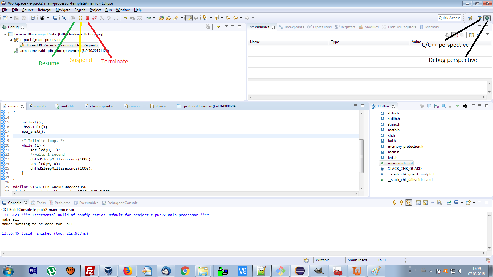
- Click on the
Resumebutton on top of the window to start your program. Now you can suspend and resume whenever you want, then when you want to modify your code again you click on theTerminatebutton and click on theC/C++ perspectivebutton.