|
|
| Line 1: |
Line 1: |
| This is a mini how-to of the e-puck extension board for the Gumstix Overo COM.
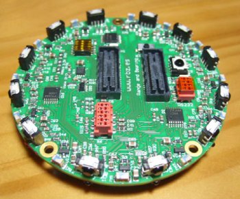
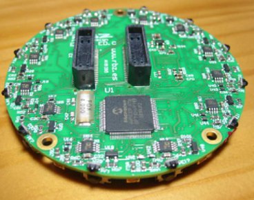
| | =Range and bearing= |
| | <span class="plainlinks">[http://www.gctronic.com/doc/images/randb-1-small.jpg <img height=150 src="http://www.gctronic.com/doc/images/randb-1.jpg">][http://www.gctronic.com/doc/images/randb-2-small.jpg <img height=150 src="http://www.gctronic.com/doc/images/randb-2.jpg">]</span><br/> |
| | The board allows situated agents to communicate locally, obtaining at the same time both the range and the bearing of the emitter without the need of any centralized control or any external reference. Therefore, the board allows the robots to have an embodied, decentralized and scalable communication system. The system relies on infrared communications with frequency modulation and is composed of two interconnected modules for data and power measurement.<br/> |
|
| |
|
| =Minimal getting started=
| | The documentation and hardware files are available in the following links: |
| {| style="color:black; background-color:#ffffcc;" cellspacing="0" border="1"
| | * [https://projects.gctronic.com/randb/eRandB_Ed.D_Schematics.pdf Schematics (pdf)] |
| |
| | * [https://projects.gctronic.com/randb/eRandB_Ed.D_Assembling.pdf Assembling (pdf)] |
| # upload the [http://www.gctronic.com/doc/index.php/E-Puck#Standard_firmware standard firmware] to the e-puck robot and put selector in position 10
| | * [https://projects.gctronic.com/randb/eRandB_Ed.D_BillOfMaterials.xls Bill of Materials (xls)] |
| # connect the USB cable: mini-USB to the extension module and the other side to the PC
| | * [https://projects.gctronic.com/randb/eRandB_Ed.D_PCB.pdf PCB (pdf)] |
| # execute a terminal program (e.g. minicom) and configure the connection with 115200-8N1. The serial device path should be typically something like "/dev/ttyUSB0". Make sure that the flow control parameter of minicom called "Hardware" is set to "No".
| | * [https://projects.gctronic.com/randb/eRandB_Ed.D_HardwareSourceFiles.zip Hardware source files(zip)] |
| # switch on the robot; now the terminal should display the Gumstix Overo booting information (booting time 25-30 seconds)
| | * [https://projects.gctronic.com/randb/eRandB_Ed.D_Fabrication.zip Fabrication: Gerber, pick and place, ... (zip)] |
| # login with user=root, password=root
| | * [https://projects.gctronic.com/randb/eRandB_manual.pdf e-RandB manual (pdf)] |
| |}
| | * [https://projects.gctronic.com/randb/eRandB_firmware.zip e-RandB firmware (zip)] |
| | * [https://projects.gctronic.com/randb/eRandB_software.tgz e-puck software and examples (tgz)] |
|
| |
|
| <font style="color:red"> Anyway you're encouraged to read all the documentation since you'll find more detailed explanations. </font>
| | You can find more information about this board in the following links: [http://www.e-puck.org/index.php?option=com_content&view=article&id=35&Itemid=23 http://www.e-puck.org/index.php?option=com_content&view=article&id=35&Itemid=23]. |
|
| |
|
| =Introduction=
| | The following table lists the I2C the registers map: |
| <span class="plainlinks">[http://www.gctronic.com/doc/images/Ext+robot1.jpg <img width=200 src="http://www.gctronic.com/doc/images/Ext+robot1.jpg">]</span> <br/> | | <blockquote> |
| This introductory section explains the minimal procedures needed to work with the Gumstix Overo computer-on-module (COM) mounted on the e-puck extension board and gives a general overview of the available demos and scripts shipped with the micro sd. You can also refer to [http://projects.gctronic.com/Gumstix/extension-instructions.pdf extension-instructions] that is a document containing the most important information in order to start working with the extension. The extension is mostly an interface between the e-puck robot and the Gumstix Overo COM.
| | {| border="1" cellpadding="10" cellspacing="0" |
| | | !Address !!Read !!Write |
| Gumstix Overo COM: [http://www.gumstix.com product information] and [http://www.gumstix.org programming information],
| | |- |
| | | |0 || 1 if data available, 0 otherwise || - |
| ==Full package==
| | |- |
| The full package content is:
| | |1 || data MSB || - |
| * e-puck extension with Gumstix Overo COM and micro sd card already inserted
| | |- |
| * USB adapter for the micro sd
| | |2 || data LSB || - |
| * A to mini-B USB cable
| | |- |
| * USB wifi dongle
| | |3 || bearing MSB || - |
| * external power adapter
| | |- |
| * USB host adapter
| | |4 || bearing LSB: <code>double((MSB<<8)+LSB)*0.0001</code> to get angle in degrees|| - |
| The standard COM mounted on the e-puck extension is the Gumstix Overo EarthSTORM COM. Some extensions were delivered with the Gumstix Overo SandSTORM COM, don't worry, the main difference between the two COMs is that the SandSTORM has no flash memory, but the flash isn't necessary since the system is booted from the micro sd.
| | |- |
| | | |5 || range MSB || - |
| ==Requirements==
| | |- |
| In order to connect to the extension through the mini USB the FTDI driver need to be installed. If a serial port is automatically created when connecting the robot to the computer you're done otherwise visit the following site and download the drivers for your architecture (32 or 64 bits) [http://www.ftdichip.com/Drivers/VCP.htm FTDI drivers].
| | |6 || range LSB || - |
| | | |- |
| ==General procedure==
| | |7 || max peak (adc reading) MSB || - |
| The e-puck extension board for the Gumstix Overo COM comes with a pre-configured system ready to run without any additional configuration. The whole system is installed on a micro sd and is composed of:
| | |- |
| * U-Boot (bootloader customized for the hardware)
| | |8 || max peak (adc reading) LSB || - |
| <!--* OMAP35x Linux PSP [https://www-a.ti.com/downloads/sds_support/targetcontent/psp/omap35x/index.html https://www-a.ti.com/downloads/sds_support/targetcontent/psp/omap35x/index.html] (linux kernel) -->
| | |- |
| * OMAP35x Linux TI-PSP [http://arago-project.org/git/people/?p=sriram/ti-psp-omap.git;a=summary http://arago-project.org/git/people/?p=sriram/ti-psp-omap.git;a=summary] (linux kernel)
| | |9 || sensor that received the data (between 0..11) || - |
| * some demos and useful scripts in the /home/root directory
| | |- |
| It's important to note that the flash isn't reprogrammed, so it will contain the factory system.
| | |12 || - || Set transmission power (communication range): between 0 (max range) and 255 (min range) |
| | | |- |
| In order to access the system from a PC (console mode), the following steps must be performed:
| | |13 || - || data LSB (prepare) |
| # connect the USB cable: mini-USB to the extension module and the other side to the PC
| | |- |
| # execute a terminal program (e.g. minicom) and configure the connection with 115200-8N1. The serial device path should be typically something like "/dev/ttyUSB0". Make sure that the flow control parameter of minicom called "Hardware" is set to "No".
| | |14 || - || data MSB (send <code>(MSB<<8)+LSB</code>) |
| # switch on the robot; now the terminal should display the Gumstix Overo booting information (booting time 25-30 seconds)
| | |- |
| # login with user=root, password=root
| | |16 || - || 0 store light conditions (calibration) |
| | | |- |
| ==Wireless setup==
| | |17 || - || 1=onboard calculation, 0=host calculation |
| Before proceding with the following configurations be sure that the WiFi dongle is well recognized, refer to section [http://www.gctronic.com/doc/index.php/Overo_Extension#WiFi_dongle WiFi_dongle].
| | |- |
| ===Wireless configuration using a script===
| | |} |
| The script ''setupWifi'' placed under /home/root/scripts is used to configure easily the wireless network (managed mode) and need to be adapted to your specific situation. The script is shown below:
| | </blockquote> |
| <pre>
| |
| #!/bin/bash
| |
| ifconfig wlan0 up
| |
| iwconfig wlan0 essid SSID key HEX_KEY
| |
| iwconfig wlan0 ap MAC_ADDRESS
| |
| iwconfig wlan0 rate 54M
| |
| ifconfig wlan0 LOCAL_IP netmask SUBNET_MASK
| |
| route add default gw GATEWAY_IP
| |
| </pre> | |
| To know the available wifi networks and related information such as mac address of the access point, you can issue the command ''iwlist scanning wlan0''.
| |
| | |
| On some platforms, udev may rename the network interface ''wlan0.'' In this event, the 'setupWifi' script will return several errors, some of which will say "No Such Device." To identify your network interfaces, use the commands ''ifconfig'' or ''iwconfig.'' These will provide a listing of your devices, and their current states. Identify the appropriate interface (typically ''wlan#'' where "#" is a number) and replace ''wlan0'' in the above script with this.
| |
| | |
| If you're using dhcp, you can instead adapt the script ''setupWifiDhcp'' found under /home/root/scripts:
| |
| <pre> | |
| #!/bin/bash
| |
| ifconfig wlan0 up
| |
| iwconfig wlan0 essid SSID key HEX_KEY
| |
| iwconfig wlan0 ap MAC_ADDRESS
| |
| iwconfig wlan0 rate 54M
| |
| dhclient wlan0
| |
| </pre> | |
| | |
| The parameters that must be customized are shown in capitals; after that you can execute the script typing ''./setupWifi'' (or ''./setupWifiDhcp'') and after a while a message should be displayed indicating that the wireless is ready. You can test the network configuration using ''ping''.
| |
| | |
| It may be necessary to create a directory if you get the error "can't create /var/lib/dhcp/dhclient.leases: No such file or directory." Use the ''mkdir'' command
| |
| | |
| <pre>
| |
| mkdir /var/lib/dhcp
| |
| </pre> | |
| | |
| Usually, when the Wifi dongle is connected to the AP, a message is written in the message buffer of the kernel. The following bash code snippet can be used to make sure that the connection is well established when the program returns:
| |
| <pre>
| |
| #!/bin/bash
| |
| echo Wait until the Wifi is connected to the AP
| |
| while true
| |
| do
| |
| #the text "link becomes ready" can vary according the Wifi dongle
| |
| a=$(dmesg | grep wlan0 | grep "link becomes ready")
| |
| if [ -n "$a" ]
| |
| then
| |
| echo Wifi enabled!
| |
| exit
| |
| fi
| |
| sleep 1
| |
| done
| |
| </pre>
| |
| | |
| In order for the ''setupWifi'' or ''setupWifiDhcp'' scripts to be run during boot, copy the appropriate script into the ''init.d'' directory with the other start/stop scripts.
| |
| <pre>
| |
| cp -i ~/scripts/setupWifi /etc/init.d/setupWifi
| |
| </pre>
| |
| Then determine which run level the system is using with the command:
| |
| <pre>
| |
| runlevel
| |
| </pre>
| |
| This should return "N #" where # is the run level number. Create a link to your script in the ''init.d'' directory within the directory ''/etc/rc#.d'' Name the link ''S##setupWifi.'' The number ## (customarily 2 digits, which you choose) determines where in the startup sequence your script will be run. It is good advice to choose a number just smaller than the largest in the ''rc#.d'' directory, this way the script is not called before lower-level ones. The creation of this link can be done with the following command (where # and ## must be changed to their appropriate values).
| |
| <pre>
| |
| ln -i -s /etc/init.d/setupWifi /etc/rc#.d/S##setupWifi
| |
| </pre> | |
|
| |
|
| ===Wireless configuration using a wpa_supplicant=== | | ==Firmware source code== |
| Alternativerly, the Wifi connection can be set up by using both [http://hostap.epitest.fi/wpa_supplicant/ wpa_supplicant] and the native wifi setup. This has the advantage to be more robust against failure. In order to do that, the Wifi interface can be added to /etc/network/interfaces, this way:
| |
| <pre>
| |
| auto wlan0
| |
| iface wlan0 inet static
| |
| address 192.168.1.2
| |
| netmask 255.255.255.0
| |
| wpa-conf /path/to/wifi.conf #this should be replaced by the absolute location of wifi.conf
| |
| </pre>
| |
|
| |
|
| And the related wifi.conf
| |
| <pre>
| |
| ctrl_interface=/var/run/wpa_supplicant
| |
| ctrl_interface_group=0
| |
| ap_scan=1
| |
| network={
| |
| ssid="myssid" #this should be replaced by your ssid
| |
| scan_ssid=1
| |
| key_mgmt=NONE
| |
| wep_key0=1234567890 #this should be replaced by your WEP key
| |
| wep_tx_keyidx=0
| |
| }
| |
| </pre>
| |
|
| |
|
| In this example, static IPs and WEP encryption have been used. DHCP and other encryption can be obviously used by following the documentation both of the linux native network setup and of [http://hostap.epitest.fi/wpa_supplicant/ wpa_supplicant].
| | ==e-puck 1== |
| | A simple [https://projects.gctronic.com/randb/test-eRandB.zip MPLAB project] was created to let start using these modules. With the selector it's possible to choose whether the robot is an emitter (selector in position 0) or a receiver (selector in position 1). The receiver will send the information (data, bearing, distance, sensor) through Bluetooth. |
|
| |
|
| ===Network performance=== | | ==e-puck 2== |
| To test the network performance you could use the ''iperf'' tool installed on the system. In the server side you must issue the following command (either for TCP or UDP testing), after which the server machine is listening for incoming data:
| | The e-puck2 standard firmware contains a demo example to use the range and bearing extension. When the selector is in position 4 then the robot is the receiver, when in position 5 then the robot is the transmitter. The receiver will print (you need to connect the USB cable and open the USB serial port) the data received, the bearing, the distance and the sensor id; while the transmitter will send continously <code>0xAAFF</code>.<br/> |
| <pre> | | You can download the pre-built firmware from [https://projects.gctronic.com/epuck2/e-puck2_main-processor_randb.elf e-puck2_main-processor_randb.elf]; the source code is available form the repo [https://github.com/e-puck2/e-puck2_main-processor https://github.com/e-puck2/e-puck2_main-processor].<br/> |
| iperf -s [TCP]
| | Beware that the only communication channel available between the robot and the range and bearing extension is the I2C bus, the UART channel is not available with e-puck 2. |
| iperf -s -u [UDP]
| |
| </pre>
| |
| In the client side you must type:
| |
| <pre>
| |
| iperf -c SERVER-IP [TCP]
| |
| iperf -c SERBER-IP -u -b 50000000 [UDP]
| |
| </pre> | |
| Where ''SERVER-IP'' must be changed accordingly to the network configuration.
| |
|
| |
|
| ==Package manager== | | =Ground sensors= |
| If you have an internet connection up and running you can update and install easily new packages with ''opkg''. Some of the useful operations you could do are:
| | <span class="plainlinks">[http://www.gctronic.com/doc/images/E-puck-groundsensors.jpg <img width=200 src="http://www.gctronic.com/doc/images/E-puck-groundsensors.jpg">]</span> |
| * update repositories: <code>opkg update</code>
| |
| * update installed packages and kernel; pay attention that the camera driver is based on the provided kernel and upgrading it will prevent the use of the camera: <code>opkg upgrade</code>
| |
| * list of software currently installed on the machine: <code>opkg list_installed</code>
| |
| * install a new package (perl in the example): <code>opkg install perl</code>
| |
| * remove a pacakge (perl in the example): <code>opkg remove perl</code>
| |
| * list of all packages available to be installed: <code>opkg list</code>
| |
|
| |
|
| ===opkg update failed===
| | The factory firmware of both the e-puck1 and e-puck2 supports the ground sensors extension: for e-puck1 refer to the section [https://www.gctronic.com/doc/index.php?title=E-Puck#Standard_firmware Standard firmware], for e-puck2 refer to section [https://www.gctronic.com/doc/index.php?title=e-puck2#Factory_firmware Factory firmware]. |
| If you get errors on reaching the default repo sources you can try changing them by following these steps:
| |
| # make a copy of the current repo: <code>mv /etc/opkg/base-feed.conf /dest-dir</code>
| |
| # add the new repo: <code>echo 'src/gz base http://feeds.angstrom-distribution.org/feeds/unstable/ipk/glibc/armv7a/base' > /etc/opkg/base-feed.conf</code> | |
| # opkg update | |
| The procedure shows how to change the <code>base</code> repo, the same need to be done for all others repos.
| |
|
| |
|
| ==USB ports==
| | Once the robot is programmed with its factory firmware, you can get the values from the ground sensors through Bluetooth by putting the selector in position 3 and issueing the command <code>m</code> that will return 5 values, the first 3 values are related to the ground sensors (left, center, right), the last 2 values are related to the cliff extension (if available).<br/> |
| The e-puck extension board for the Gumstix Overo COM comes with two USB interfaces called USB host and USB otg. If you try inserting devices that require more energy than the one permitted on the otg, the device will not be enabled automatically. In these cases you can use the three scripts ''usbup'', ''usbdown'' and ''usbenable'' to respectively power up, power down and enable the USB device; they're placed under /home/root/scripts. These scripts are intended for primary use with the USB otg port, even if they're suitable for both ports (otg and host).
| | For more information about the Bluetooth connection refer to section [https://www.gctronic.com/doc/index.php?title=E-Puck#Getting_started Getting started] (e-puck1) or [https://www.gctronic.com/doc/index.php?title=e-puck2_PC_side_development#Connecting_to_the_Bluetooth Connecting to the Bluetooth] (e-puck2).<br/> |
| * ''./usbup otg'' (or ''./usbup host''): power on the usb device
| | For more information about the Bluetooth protocol refer to section [https://www.gctronic.com/doc/index.php?title=Advanced_sercom_protocol Advanced sercom protocol]. |
| * ''./usbdown otg'' (or ''./usbdown host''): power off the usb device
| |
| * ''./usbenable otg'' (or ''./usbenable host''): activate the usb device (now is in the usb device list)
| |
|
| |
|
| ==Demos==
| | If you couple the e-puck extension for Gumstix Overo with the ground sensor refer to the section [http://www.gctronic.com/doc/index.php/Overo_Extension#Ground_sensor http://www.gctronic.com/doc/index.php/Overo_Extension#Ground_sensor] to have an example on how to read the sensor values. |
| A specific firmware must be charged on the e-puck to run the Gumstix Overo linked demos, refer to section [http://www.gctronic.com/doc/index.php/Overo_Extension#E-puck_firmware E-puck firmware].
| |
|
| |
|
| ===Serial test on the Gumstix Overo COM===
| | You can find more information about the ground sensors extension module in the following link [http://www.e-puck.org/index.php?option=com_content&view=article&id=17&Itemid=18 http://www.e-puck.org/index.php?option=com_content&view=article&id=17&Itemid=18].<br/> |
| This small program read and write from a serial port (non-canonical mode). For more information on the usage refers to [http://docwiki.gumstix.org/index.php?title=Sample_code/C/Serial sertest] ([http://projects.gctronic.com/Gumstix/sertest.tar.gz sertest sources]). It's placed under /home/root/demos/gumstix-common, and it's called ''sertest''.
| |
|
| |
|
| ===Advanced sercom=== | | ==Assembly for e-puck2== |
| Once the new firmware is running on the e-puck, the selector must be set in position 10 to run the advanced sercom for the Gumstix Overo. <br/>
| | <span class="plainlinks"><table><tr><td align="center">[1]</td><td align="center">[2]</td><td align="center">[3.1]</td><td align="center">[3.2]</td><td align="center">[3.3]</td><td align="center">[3.4]</td></tr><tr><td align="center">[https://projects.gctronic.com/epuck2/wiki_images/ground-assembly-1.png <img height=200 src="https://projects.gctronic.com/epuck2/wiki_images/ground-assembly-1_small.png">]</td><td align="center">[https://projects.gctronic.com/epuck2/wiki_images/ground-assembly-2.png <img height=200 src="https://projects.gctronic.com/epuck2/wiki_images/ground-assembly-2_small.png">]</td><td align="center">[https://projects.gctronic.com/epuck2/wiki_images/ground-assembly-3.1.png <img height=200 src="https://projects.gctronic.com/epuck2/wiki_images/ground-assembly-3.1_small.png">]</td><td align="center">[https://projects.gctronic.com/epuck2/wiki_images/ground-assembly-3.2.png <img height=200 src="https://projects.gctronic.com/epuck2/wiki_images/ground-assembly-3.2.png">]</td><td align="center">[https://projects.gctronic.com/epuck2/wiki_images/ground-assembly-3.3.jpeg <img height=200 src="https://projects.gctronic.com/epuck2/wiki_images/ground-assembly-3.3_small.jpeg">][https://projects.gctronic.com/epuck2/wiki_images/ground-assembly-3.4.jpeg <img height=200 src="https://projects.gctronic.com/epuck2/wiki_images/ground-assembly-3.4_small.jpeg">]</td><td align="center">[https://projects.gctronic.com/epuck2/wiki_images/ground-assembly-3.5.png <img height=200 src="https://projects.gctronic.com/epuck2/wiki_images/ground-assembly-3.5.png">]</td></tr><tr><td align="center">[4]</td><td align="center">[5.1]</td><td align="center">[5.2]</td><td align="center">[5.3]</td><td align="center">[5.4]</td><td align="center">[6]</td></tr><tr><td align="center">[https://projects.gctronic.com/epuck2/wiki_images/ground-assembly-4.png <img height=200 src="https://projects.gctronic.com/epuck2/wiki_images/ground-assembly-4_small.png">]</td><td align="center">[https://projects.gctronic.com/epuck2/wiki_images/ground-assembly-5.1.png <img height=200 src="https://projects.gctronic.com/epuck2/wiki_images/ground-assembly-5.1_small.png">]</td><td align="center">[https://projects.gctronic.com/epuck2/wiki_images/ground-assembly-5.2.png <img height=200 src="https://projects.gctronic.com/epuck2/wiki_images/ground-assembly-5.2_small.png">]</td><td align="center">[https://projects.gctronic.com/epuck2/wiki_images/ground-assembly-5.3.png <img height=200 src="https://projects.gctronic.com/epuck2/wiki_images/ground-assembly-5.3_small.png">]</td><td align="center">[https://projects.gctronic.com/epuck2/wiki_images/ground-assembly-5.4.png <img height=200 src="https://projects.gctronic.com/epuck2/wiki_images/ground-assembly-5.4_small.png">]</td><td align="center">[https://projects.gctronic.com/epuck2/wiki_images/ground-assembly-6.png <img height=200 src="https://projects.gctronic.com/epuck2/wiki_images/ground-assembly-6_small.png">]</td></tr></table></span> |
| Now you can type (after being in /home/root/demos/gumstix-common) ''./sertest -p /dev/ttyS0 -b 230400'' (or simply ''./ser+ENTER'') to enter the e-puck menu in console mode; for a list of all available commands type ''h+ENTER''. After stopping the sertest program (CTRL+C), the display may not respond correctly; to reset the display run the script ''r'' by simply typing ''./r+ENTER''. Now the display should behave normally.<br/>
| | # Unscrew the 3 spacers and remove the battery. |
| For more information about the advanced sercom refer to the page [http://www.gctronic.com/doc/index.php/Advanced_sercom_protocol Advanced sercom protocol].
| | # Remove the top side from the case body gently. |
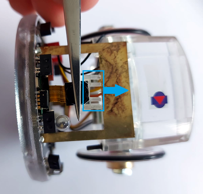
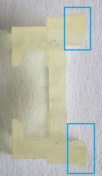
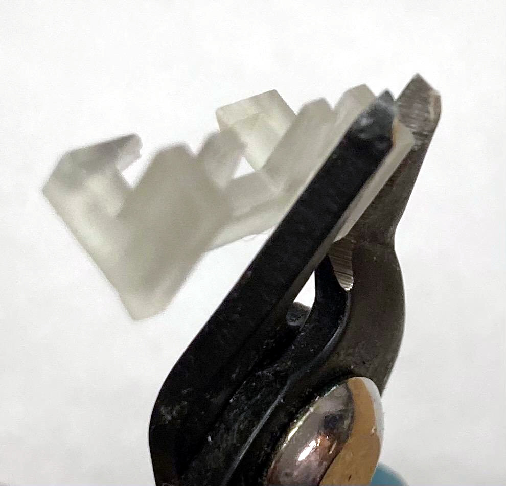
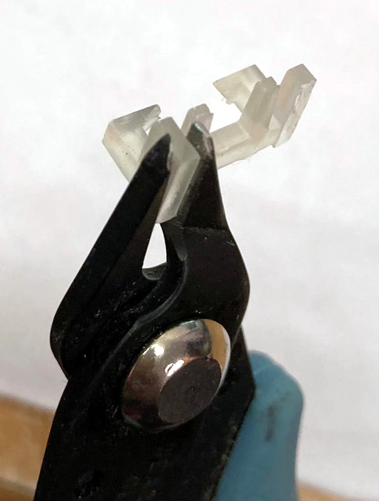
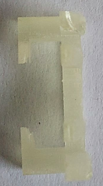
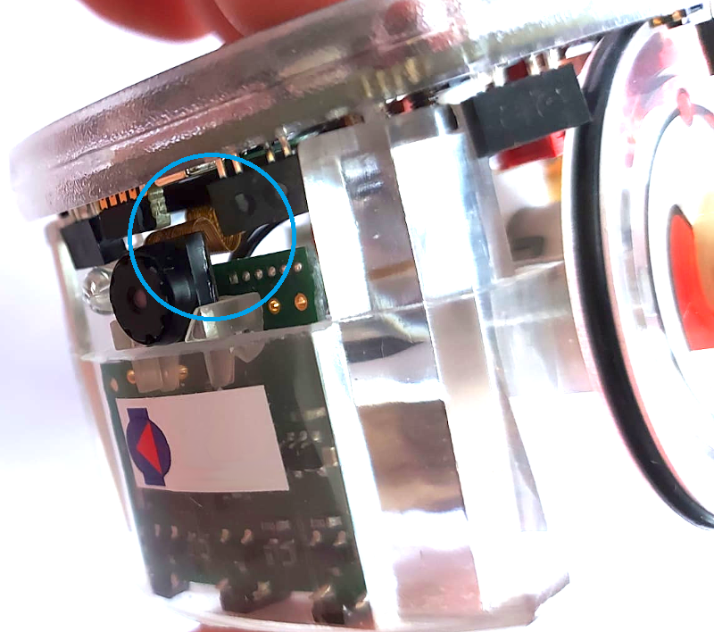
| | # Detach the plastic camera adapter from the camera with the help of pliers; be careful to not stress the camera flex cable. Then you need to cut off the two protruding pieces (see 3.2) on the back of the plastic adapter; for this operation you can use nippers (see 3.3). Take the adapter (now is flat on the back as shown in 3.4) and insert it as before. |
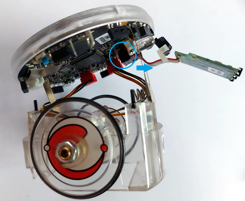
| | # Plug the ground module into its connector on the e-puck2; make the cable pass through the battery contact. |
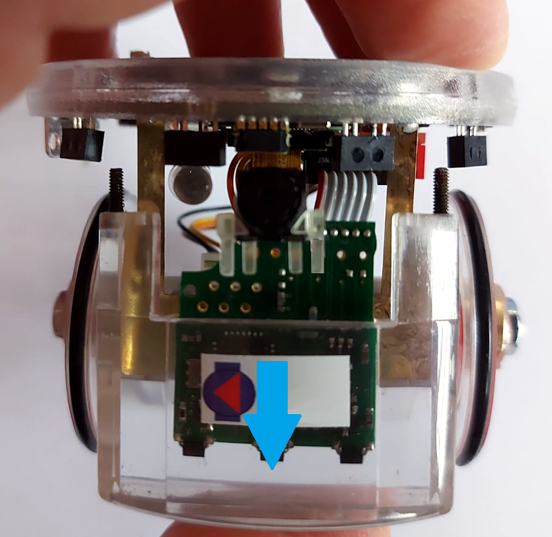
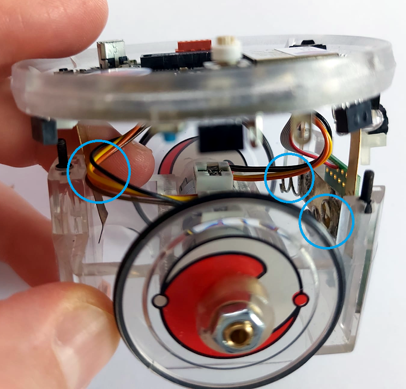
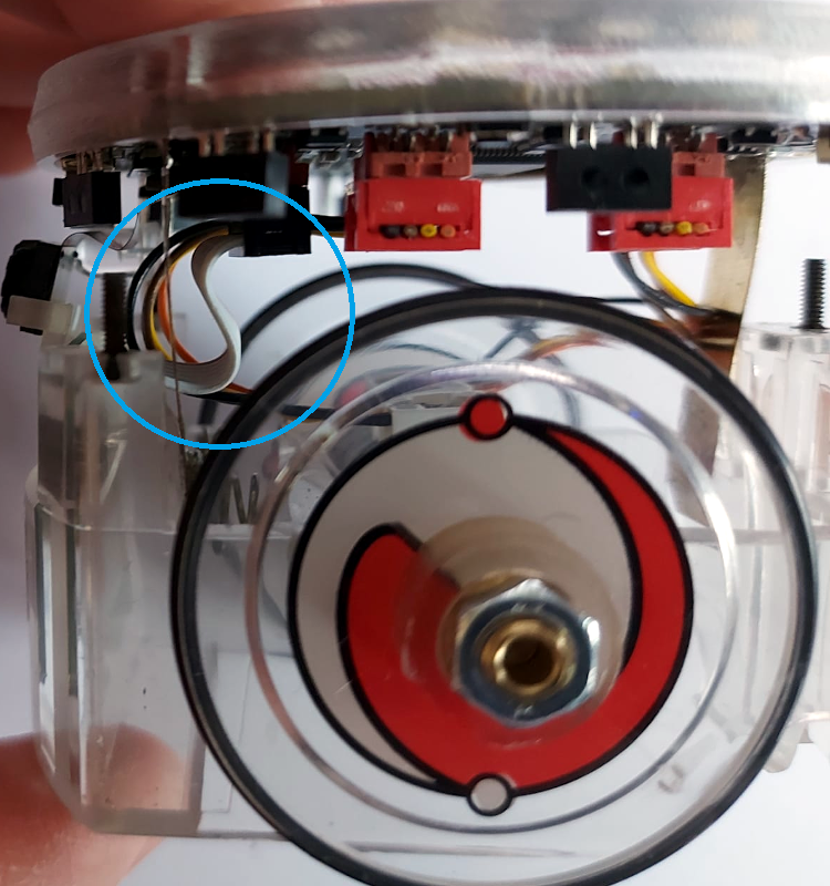
| | # First push the ground module within its slot in the body case, then slide in also the top side of the robot paying attention to the motors wires position: the back battery contact must remain between the body and motors wires and make sure the wires aren't stuck in the springs. Both the ground cable and camera flex cable must bend forming an "S" shape. |
| | # Push the top all way down, then remount the spacers and plug in the battery. You're done. |
|
| |
|
| ===Images grabbing (camera driver)=== | | =Cliff sensor= |
| <!-- A small utility called ''v4l2grab'' was used for grabbing JPEGs from V4L2 devices ([http://github.com/twam/v4l2grab http://github.com/twam/v4l2grab]). <br/>
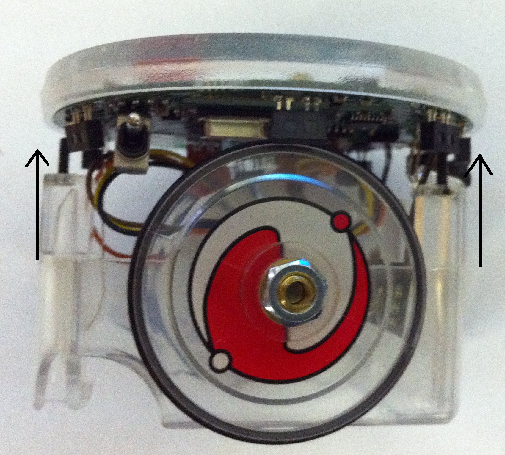
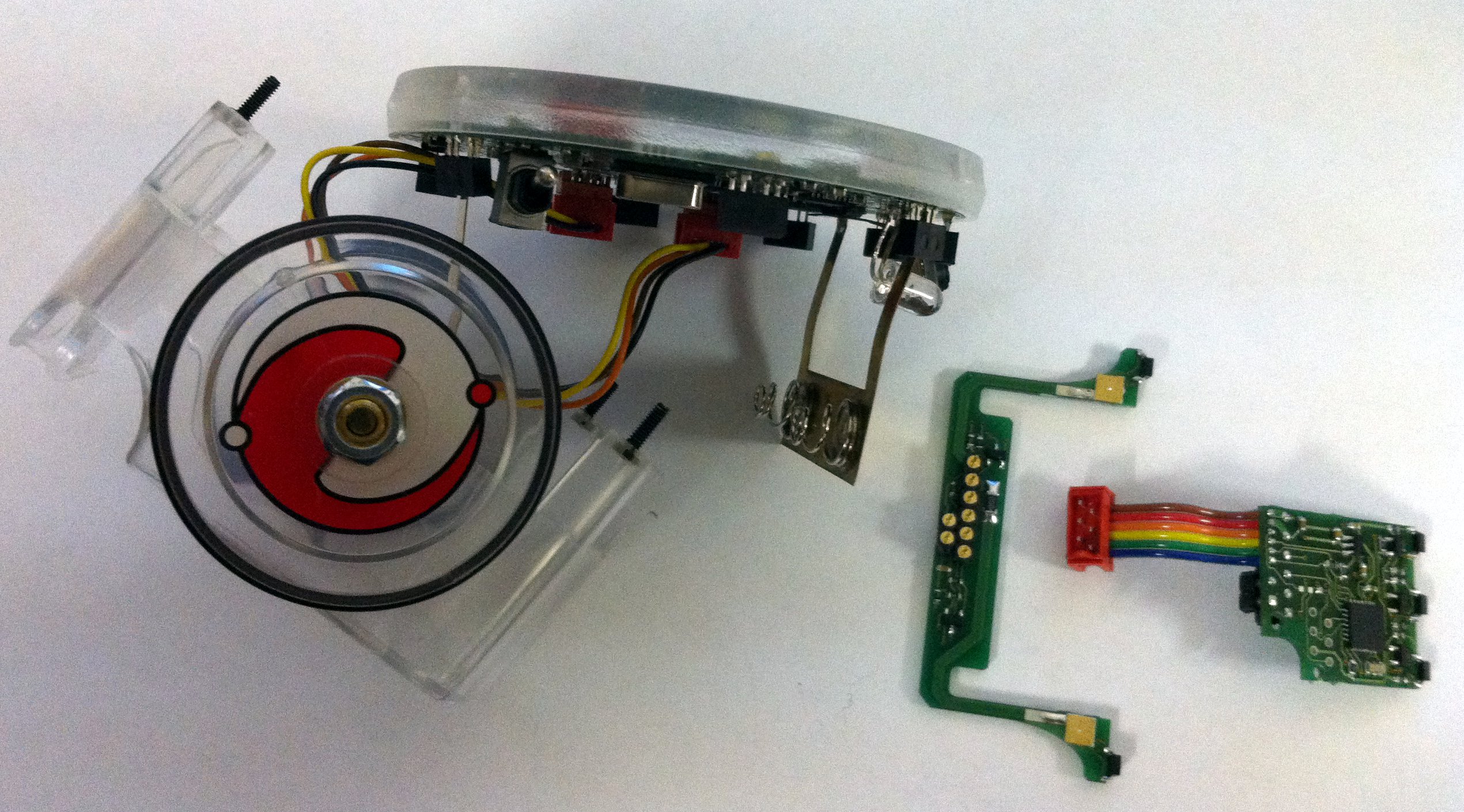
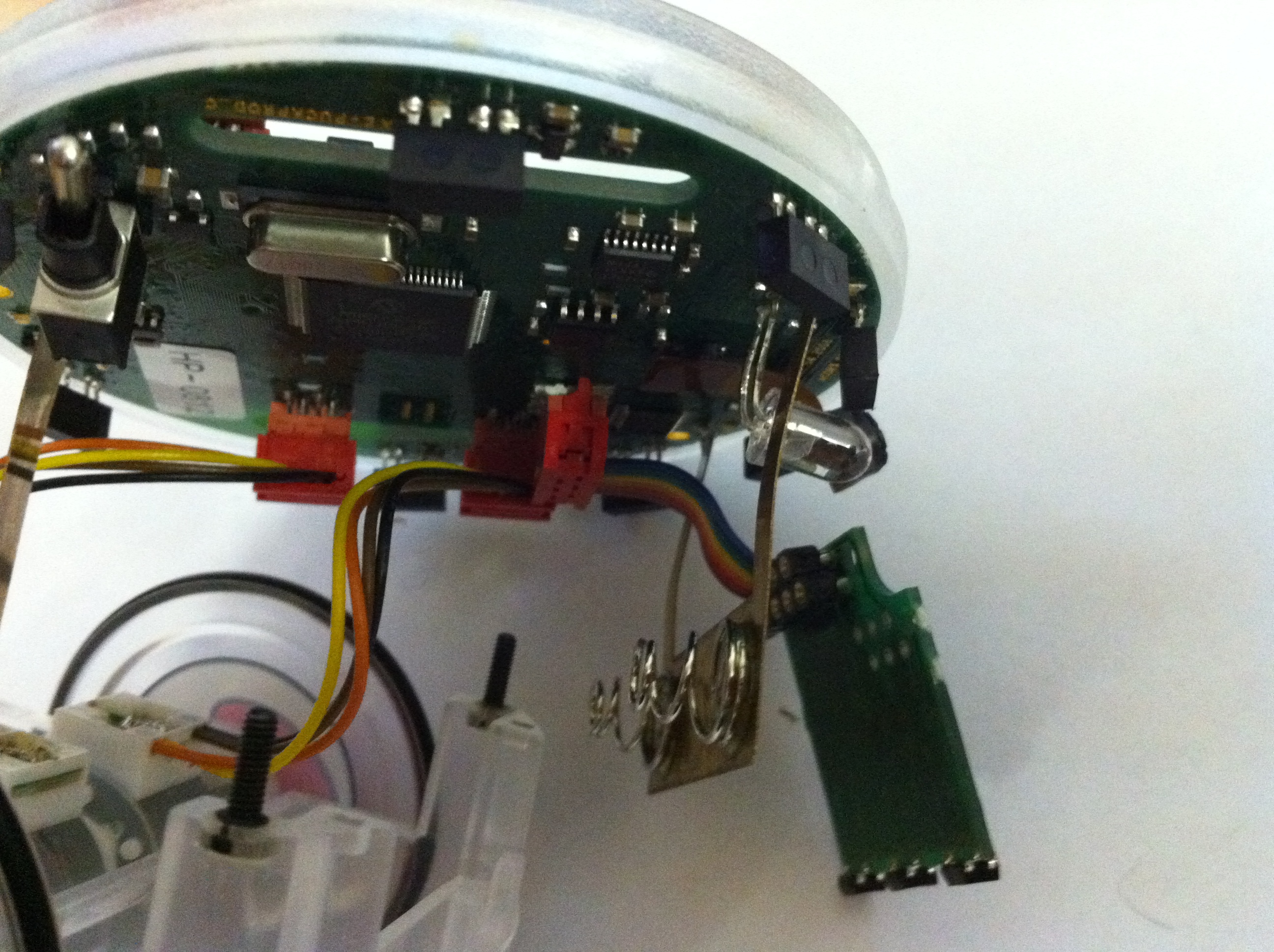
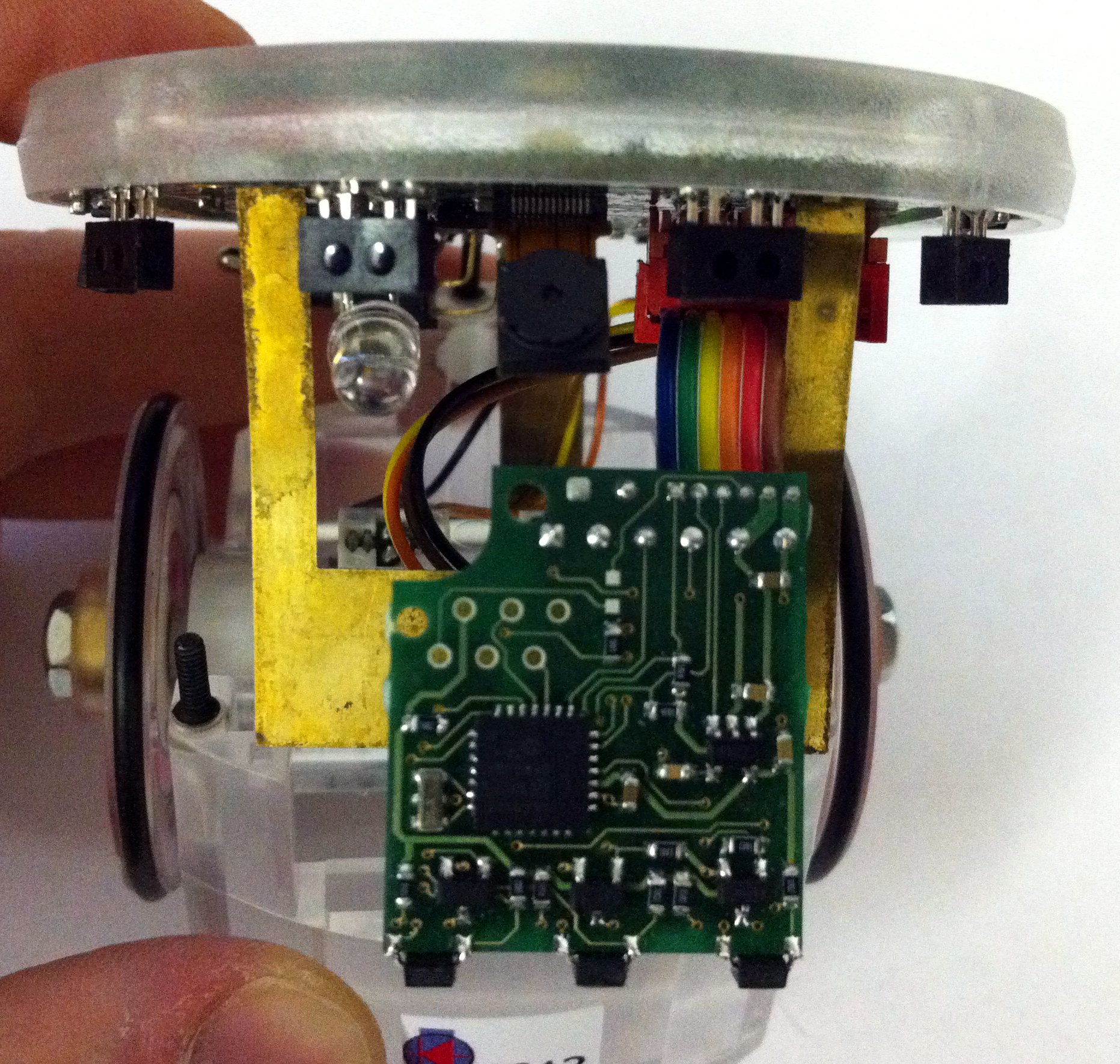
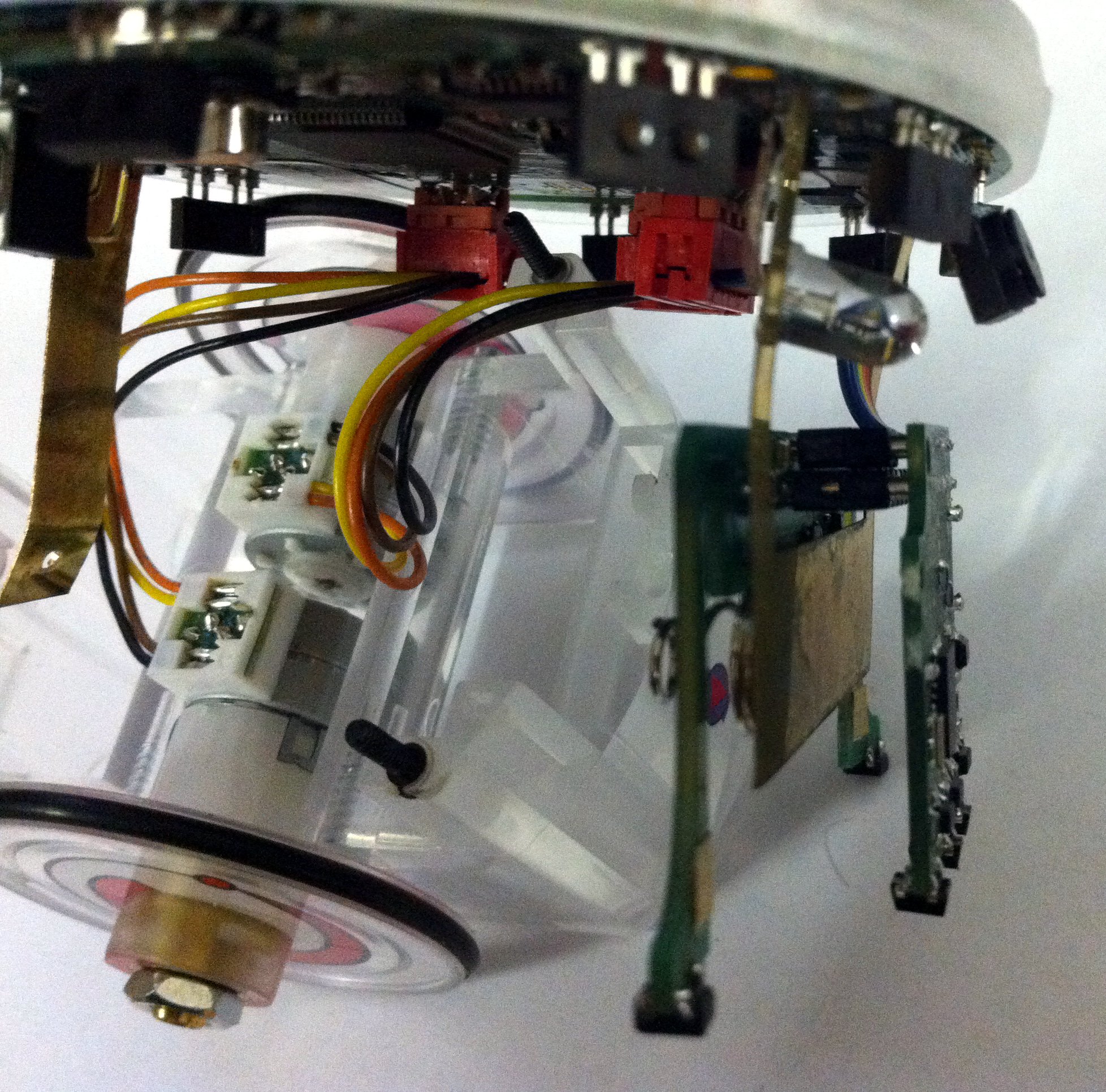
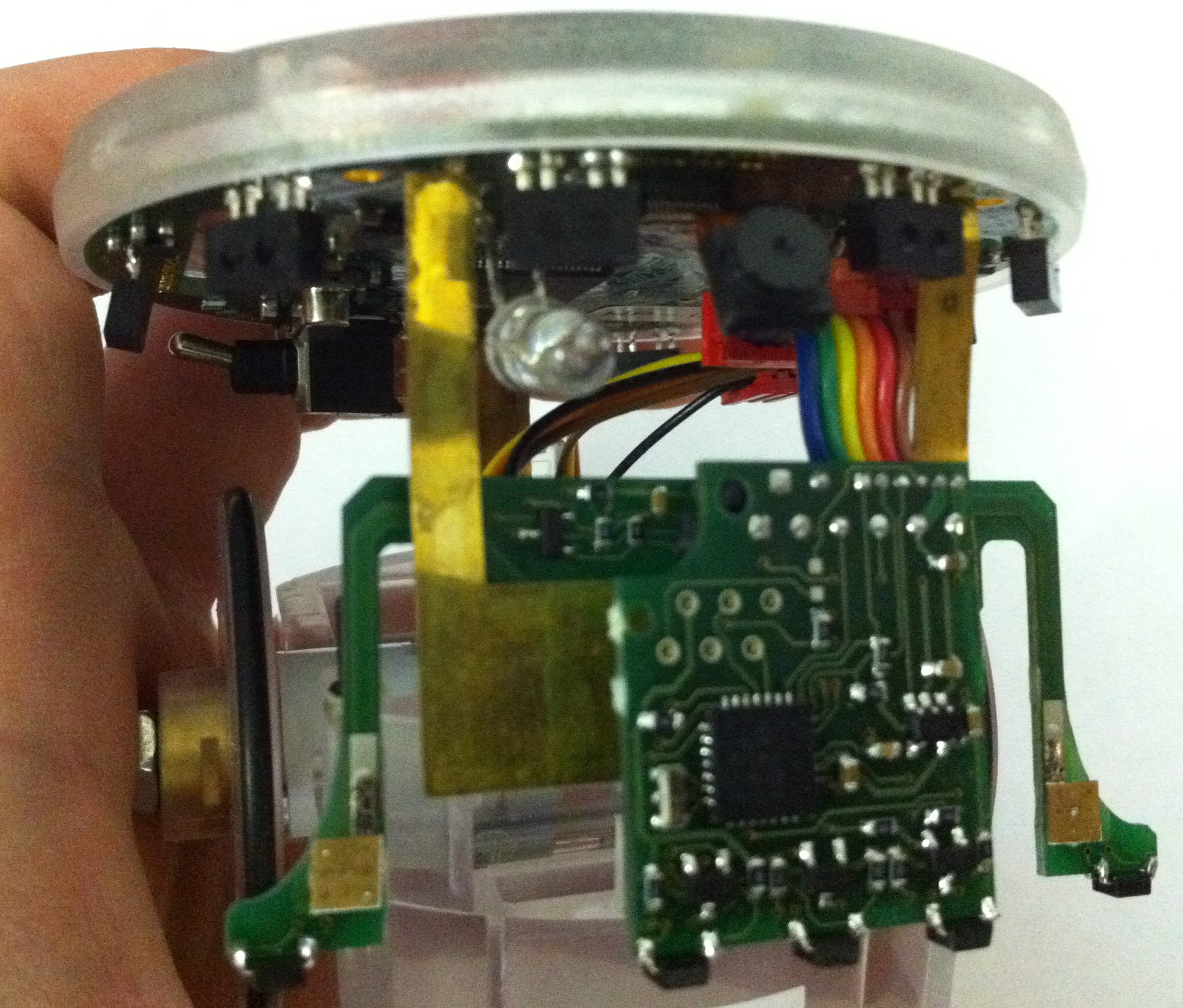
| | The cliff module extends the capability of the groundsensor with two additional sensors placed in front of the wheels. One possible application is that the e-puck can now detect the end of a table and react accordingly. Moreover this module can be coupled with the automatic charger for the e-puck, that could let the robot autonomously charge itself when needed. The two spring contacts adapt only to the cliff module. |
| In order to get an image from the e-puck camera you need to follow these steps:
| |
| # load the driver typing (after being in /home/root/demos) ''insmod po6030cam.ko po6030_format=1''; a message should be displayed indicating that the camera is successfully detected
| |
| # run the program typing (after being in /home/root/demos) ''./v4l2grab -o image.jpg''
| |
| For more information on the options available refer to ''./v4l2grab -h''.
| |
| -->
| |
| A small application called ''v4l2grab'' ([http://projects.gctronic.com/Gumstix/v4l2grab-2buff-rev17-13.08.14.zip v4l2grab.zip]) based on [http://github.com/twam/v4l2grab http://github.com/twam/v4l2grab] was used for grabbing JPEGs from V4L2 devices. In order to get an image from the e-puck camera you need to run the program typing (after being in <code>/home/root/demos/gumstix-common/</code>) <code>./v4l2grab -o image.jpg</code>. The application communicates also with the robot through the serial line to know the camera orientation and rotates the image automatically in case the camera is rotated (refer to section [http://www.gctronic.com/doc/index.php/E-Puck#Camera e-puck camera] for more information on camera orientation).
| |
| For more information on the options available refer to the help by typing<code>./v4l2grab -h</code>.
| |
|
| |
|
| ===Images transfer (camera driver)=== | | ==Assembly== |
| This demo is divided in two parts: one running on the e-puck extension board for the Gumstix Overo COM that continuously request images to the e-puck camera and transfers them over UDP, and the other running on a PC that acts as a server and is listening for the images visualizing them as soon as they are available. A network link must be established between the two in order to run this demo; for more information on how to configure the network refer to the section [http://www.gctronic.com/doc/index.php/Overo_Extension#Wireless_setup Wireless setup].
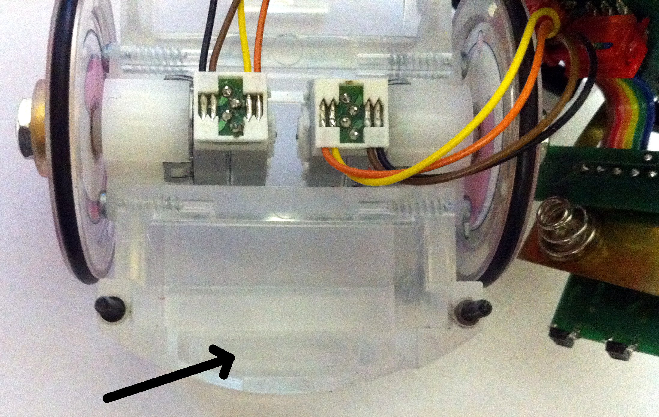
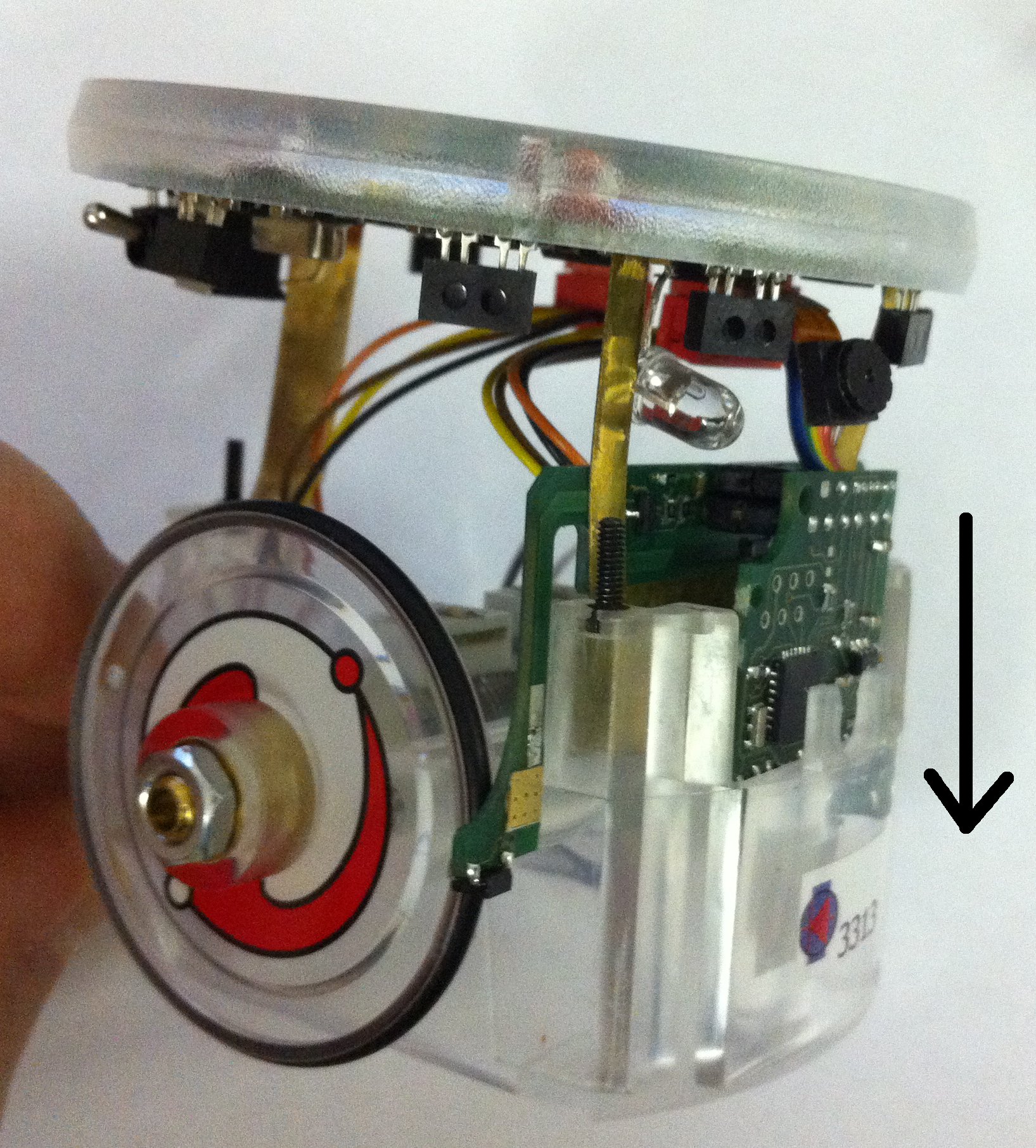
| | <span class="plainlinks"><table><tr><td align="center">[1]</td><td align="center">[2]</td><td align="center">[3]</td><td align="center">[4.1]</td><td align="center">[4.2]</td></tr><tr><td>[http://www.gctronic.com/doc/images/cliff-mounting-1.jpg <img height=200 src="http://www.gctronic.com/doc/images/cliff-mounting-1-small.jpg">]</td><td>[http://www.gctronic.com/doc/images/cliff-mounting-2.jpg <img height=200 src="http://www.gctronic.com/doc/images/cliff-mounting-2-small.jpg">]</td><td>[http://www.gctronic.com/doc/images/cliff-mounting-3.jpg <img height=200 src="http://www.gctronic.com/doc/images/cliff-mounting-3-small.jpg">]</td><td>[http://www.gctronic.com/doc/images/cliff-mounting-4-1.jpg <img height=200 src="http://www.gctronic.com/doc/images/cliff-mounting-4-1-small.jpg">]</td><td>[http://www.gctronic.com/doc/images/cliff-mounting-4-2.jpg <img height=200 src="http://www.gctronic.com/doc/images/cliff-mounting-4-2-small.jpg">]</td></tr><tr><td align="center">[5.1]</td><td align="center">[5.2]</td><td align="center">[6]</td><td align="center">[7]</td><td align="center">[8]</td></tr><tr><td>[http://www.gctronic.com/doc/images/cliff-mounting-5-1.jpg <img height=200 src="http://www.gctronic.com/doc/images/cliff-mounting-5-1-small.jpg">]</td><td>[http://www.gctronic.com/doc/images/cliff-mounting-5-2.jpg <img height=200 src="http://www.gctronic.com/doc/images/cliff-mounting-5-2-small.jpg">]</td><td>[http://www.gctronic.com/doc/images/cliff-mounting-6.jpg <img height=200 src="http://www.gctronic.com/doc/images/cliff-mounting-6-small.jpg">]</td><td>[http://www.gctronic.com/doc/images/cliff-mounting-7.jpg <img height=200 src="http://www.gctronic.com/doc/images/cliff-mounting-7-small.jpg">]</td><td>[http://www.gctronic.com/doc/images/cliff-mounting-8.jpg <img height=200 src="http://www.gctronic.com/doc/images/cliff-mounting-8-small.jpg">]</td></tr></table></span> |
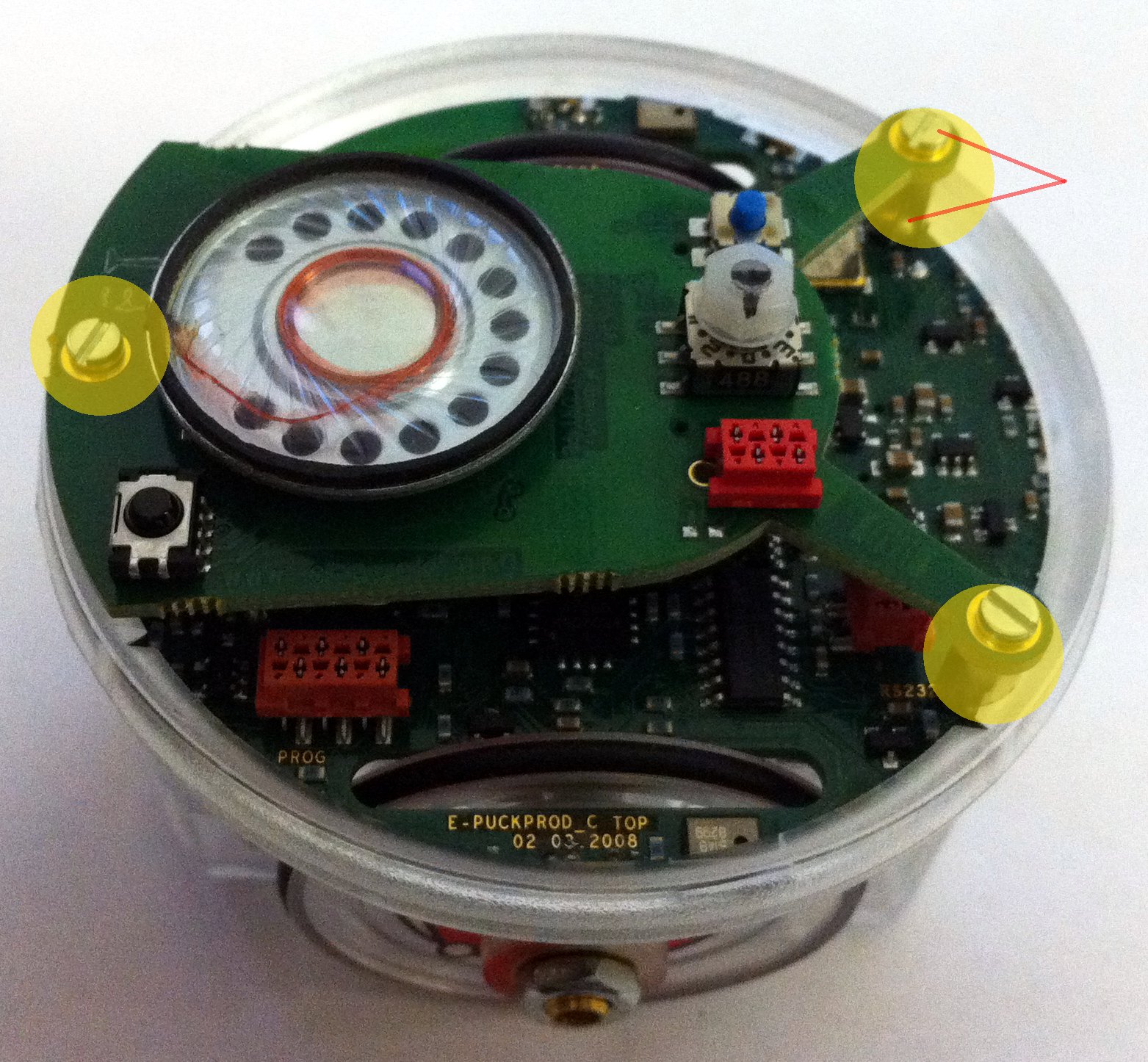
| | | # Unscrew the 3 screws, unmount the e-jumper (top piece where there is the speaker) and unscrew the 3 spacers |
| First of all you need to start the server ([http://projects.gctronic.com/Gumstix/Receiver.zip Receiver QT project]). The application is a Qt project, so the compilation may be handled easily with [https://wiki.qt.io/Category:Tools::QtCreator Qt Creator]; alternatively [http://doc.qt.io/qt-5/qmake-manual.html qmake] can be used. The usage is very simple: the server listening port and the protocol (only UDP available at the moment) must be selected first, then click on the button ''Connect''; at this moment the application is waiting images.<br/>
| | # Remove the pcb from the case body gently |
| On the e-puck extension board side, you need to run the program typing (after being in /home/root/demos) ''./v4l2grab-send -o image.jpg -i SERVER_IP -p SERVER_PORT -f 0 -t 0''. ''SERVER_IP'' is the address of the PC and ''SERVER_PORT'' should be the same as configured when the receiver was started. The ''f'' option indicates the format (in this case RGB) and ''t'' indicates the transfer mode (0=UDP, 1=TCP).
| | # Detach the two parts, cliff and ground pcb |
| <!--
| | # Plug the ground module into its connector on the e-puck |
| On the e-puck extension board side, you need to follow these steps:
| | # Attach the cliff module to the ground module being careful to leave the battery contact in the middle |
| # load the driver typing (after being in /home/root/demos) ''insmod po6030cam.ko po6030_format=0''; a message should be displayed indicating that the camera is successfully detected
| | # Push the ground module within its slot in the body case, the cliff module will remain external |
| # run the program typing (after being in /home/root/demos) ''./v4l2grab-send -o image.jpg -i SERVER_IP -p SERVER_PORT -f 0 -t 0''. ''SERVER_IP'' is the address of the PC and ''SERVER_PORT'' should be the same as configured when the receiver was started. The ''f'' option indicates the format (in this case RGB) and ''t'' indicates the transfer mode (0=UDP, 1=TCP but still not available).
| | # Once both the modules are aligned, push them down |
| -->
| | # The modules will remain really close to the case bottom; once the modules are fitted remount the spacers, the e-jumper and the screws |
| For more information on the options available refer to ''./v4l2grab-send -h''. <br/>
| |
| The sources for the sender, that is an extension of the ''v4l2grab'' application, could be found in the following link [http://projects.gctronic.com/Gumstix/v4l2grab-send.zip v4l2grab-send.zip]; in order to compile the application the ''Makefile'' must be modified specifying the path to the cross-compiler (for more information on cross-compilation for the OMAP3530 processor refers to [http://focus.ti.com/docs/prod/folders/print/omap3503.html http://focus.ti.com/docs/prod/folders/print/omap3503.html]).
| |
| | |
| ===Music player=== | |
| This isn't really a demo, it's only one of the possible way on how to listen something from the extension module. The system comes with a tool called [http://www.mplayerhq.hu/ mplayer] that supports many multimedia formats. You can use it to play for example an mp3 file in this way:
| |
| <pre>
| |
| mplayer file.mp3
| |
| </pre>
| |
| You can then adjust the volume with either the ''alsamixer'' graphical tool (adjusting DAC2 control) or using the command line tool ''amixer''; the following command can be used for instance to set the volume to 80%:
| |
| <pre>
| |
| amixer set 'DAC2 Analog' 80%
| |
| </pre>
| |
| | |
| ==File transfer==
| |
| ===ssh===
| |
| The e-puck extension board for the Gumstix Overo COM supports ssh connections through dropbear (small SSH 2 server and client) that is installed on the system.<br/>
| |
| To exchange file between the module and the PC, the ''scp'' tool (secure copy) will be used; the general command is the following:
| |
| <pre> | |
| scp user@ip:path-to-file file-name
| |
| </pre>
| |
| As an example of transfer a file from the PC to the extension, let the PC user be ''stefano'' and its IP be 192.168.1.10, then the command will be:
| |
| <pre>
| |
| scp stefano@192.168.1.10:/home/stefano/file-to-send prova
| |
| </pre> | |
| The file ''file-to-send'' will be renamed in ''prova'' and placed in the current directory.
| |
| | |
| If you are working in Windows you can use [http://winscp.net WinSCP] to exchange data between the robot and the computer.
| |
| | |
| ===zmodem===
| |
| The following instructions to exchange data between the extension and the computer refer to ''minicom'' as the terminal.<br/>
| |
| If you want to receive a file, that is transfer a file from the PC to the e-puck extension board for the Gumstix Overo COM, you need to follow these steps:
| |
| # open a terminal window with minicom; now you access the linux system in console mode
| |
| # type ''lrz''
| |
| # press ''CTRL+A'' and then ''S''
| |
| # select ''zmodem'' and navigate to find the file you want to tranfer
| |
| # select the file with the ''SPACEBAR'' and then press ''ENTER'' to start the transfer
| |
| # when transfer is complete press ''ENTER'' once more to come back to the command line
| |
| For more information type ''lrz -h''.
| |
| | |
| If you want to send a file, that is transfer a file from the e-puck extension board to the PC, you need to follow these steps:
| |
| # open a terminal window with minicom; now you access the linux system in console mode
| |
| # type ''lsz file-name'', where ''file-name'' is the file you want to transfer
| |
| # when transfer is complete press ''ENTER'' to return to the command line
| |
| The file will be placed in the directory where minicom is started. For more information type ''lsz -h''.
| |
| | |
| ==Extension LEDs==
| |
| The e-puck extension board for the Gumstix Overo COM comprises 8 new small leds that can be turned on/off easily from the file system in this way:
| |
| <pre> | |
| echo 1 > /sys/class/gpio/gpio7x/value [turn on]
| |
| echo 0 > /sys/class/gpio/gpio7x/value [turn off]
| |
| </pre> | |
| where x ranges from 0 to 7. For more information on gpio refer to the section [http://www.gctronic.com/doc/index.php/Overo_Extension#GPIO_-_pins_mode GPIO - pins mode].
| |
| | |
| ==File system image== | |
| You can download the entire system running on the micro sd released with the e-puck extension board from the following links: [http://projects.gctronic.com/Gumstix/epuck-overo-e2fs-12.08.14.tar.gz file system] and [http://projects.gctronic.com/Gumstix/epuck-overo-fat-30.03.15.tar.gz FAT] (with camera driver 1.3). <br/>
| |
| In order to prepare the micro sd you can use a script ([http://projects.gctronic.com/Gumstix/prepareMicroSD.sh prepareMicroSD.sh]), in which you need only to specify where to find the two previously downloaded files and run it (''./prepareMicroSD.sh /path/to/dev'') to have your micro sd ready to be used. Alternatively you can have a look the gumstix documentation on how to [http://www.gumstix.org/create-a-bootable-microsd-card.html create a bootable microsd card].<br/>
| |
| <!-- | |
| <font style="color:red"> A new camera driver release (1.1) is available, refer to section [http://www.gctronic.com/doc/index.php/Overo_Extension#Camera_driver Camera driver] for information on how to update the system</font>. <br/> | |
| -->
| |
| If you experience problems in booting from mmc enter u-boot and issue the following command:
| |
| <pre> | |
| nand erase 240000 20000
| |
| reset
| |
| </pre> | |
| Moreover if you need you can find pre-built images for the Gumstix Overo in the following link: [http://gumstix.org/download-prebuilt-images.html http://gumstix.org/download-prebuilt-images.html].
| |
| ===Sources=== | |
| The complete kernel sources (comprising the camera driver) can be downloaded from the following link [http://projects.gctronic.com/Gumstix/gctronic-ti-psp-omap-2.6.32-12.08.14.zip gctronic-ti-psp-omap-2.6.32-12.08.14.zip] if you want to try to build it your own (anyway you don't need to do it because the released micro SD is ready to run with this system). The system is based on:
| |
| <!--* [http://www.sakoman.com/feeds/omap3/glibc/images/overo/201005041130/ sakoman's pre-built file system image]--> | |
| * sakoman's pre-built file system image
| |
| * [http://arago-project.org/git/people/?p=sriram/ti-psp-omap.git;a=summary ti-psp-2.6.32 kernel]
| |
| | |
| ===Camera driver=== | |
| The driver of the camera is open-source, you can download the code in the section [http://www.gctronic.com/doc/index.php/Overo_Extension#Sources kernel source]. The driver is located in <code>/ti-psp-omap/drivers/media/video/po6030cam.c</code>; related ISP code is located in <code>/ti-psp-omap/drivers/media/video/isp</code>.
| |
| ====Release notes====
| |
| :1.0
| |
| * support for PO6030 camera (front e-puck camera or camera of omnicam module version 1)
| |
| * support for RGB565 output format
| |
| * only 640x480 resolution images
| |
| :1.1
| |
| * added support for PO3030 camera
| |
| * added support for YUV422 output format
| |
| * brightness, contrast, saturation, auto-white balance, red gain, blue gain controls available
| |
| :1.2
| |
| * exposure control available
| |
| * support for 480x480 color and greyscale images
| |
| :1.3
| |
| * added support for PO8030 camera
| |
| | |
| ====System update==== | |
| In order to update the system released in the micro sd with the new driver you need to download the kernel modules from [http://projects.gctronic.com/Gumstix/driver-update/1.3/linux-2.6.32.tar.gz linux-2.6.32.tar.gz] and the kernel image from
| |
| [http://projects.gctronic.com/Gumstix/driver-update/1.3/uImage uImage]. Then: | |
| # insert the micro sd in the computer; two partitions will be recognized
| |
| # copy the kernel image (uImage) in the FAT partition
| |
| # extract the kernel modules in the second partition:
| |
| ## cd path/to/partition
| |
| ## sudo tar zxvf path/to/kernel-modules
| |
| # unmount the micro sd from the computer and insert it in the extension; at first boot type ''depmod -a'' and reboot
| |
| | |
| ==Daemon== | |
| It can be useful to start a daemon at the end of the boot process in order to run your own program at the start up of the e-puck (when the console mode won't be accessible). This can be done by placing your program executable into ''/etc/init.d'' and then:
| |
| <pre>
| |
| cp /path/to/your/executable /usr/sbin/mainProgram
| |
| cd /etc/init.d
| |
| update-rc.d mainProgram defaults 99
| |
| </pre>
| |
| | |
| The daemon can be removed by removing these files:
| |
| <pre>
| |
| rm /etc/rc*/*mainProgram*
| |
| </pre>
| |
| | |
| Remember to give execution permission to the program by typing <code>chmod +x mainProgram</code>.
| |
| | |
| =Hardware=
| |
| The following figure shows the main components offered by the e-puck extension for the Gumstix Overo COM and their interconnection with the e-puck robot and the Gumstix Overo COM.<br/>
| |
| <span class="plainlinks">[http://www.gctronic.com/doc/images/Gumstix-schema.jpg <img width=600 src="http://www.gctronic.com/doc/images/Gumstix-schema.jpg">]</span> <br/> | |
| In particular there are:
| |
| * a Gumstix Overo COMs: compatible with all Gumstix Overo COM models. The communication between the Gumstix Overo COM (OMAP 35xx) and the e-puck (dsPIC) is handled with a serial line at 230400 baud
| |
| * a mini-usb connector (console) used to enter the linux system through a terminal
| |
| * one usb otg and one usb host: these two connectors are really useful to connect whatever peripheral you need, like a WiFi dongle or simply a pen drive to extend the memory
| |
| * a speaker ([http://projects.gctronic.com/Gumstix/datasheet-speaker.pdf speaker specification]): with Linux running on the Gumstix Overo COM, it's really easy play any audio format you need or implement a speech synthesizer. If the user prefer to have the speaker on the extension linked to the e-puck processor, it can simply be done changing two small resistors
| |
| * 8 LEDs: have you ever seen a board without leds?! Anyway they are completely controllable through GPIO lines (gpio70-gpio77), for detailed information refer to section [http://www.gctronic.com/doc/index.php/Overo_Extension#GPIO_-_pins_mode GPIO - pins mode]
| |
| * an I2C connector (@5 V)
| |
| * a rotary selector: one could choose what program is running on the e-puck based on the selector position
| |
| * 2 long range infrared proximity sensors ([http://projects.gctronic.com/Gumstix/datasheet-long-range.pdf long range specification]) <!-- , up to 15-20 cm -->
| |
| * the PixelPlus PO6030 camera remains mounted on the robot, but you could receive image from it by using the OMAP ISP (Camera Interface Subsystem); this way we can receive up to 18 frames per second (VGA color images)
| |
| | |
| The following figure illustrates where the components are physically placed on the e-puck extension board for the Gumstix Overo COM. <br/> | |
| <span class="plainlinks">[http://www.gctronic.com/doc/images/Gumstix-schema2.jpg <img width=600 src="http://www.gctronic.com/doc/images/Gumstix-schema2.jpg">]</span> <br/>
| |
|
| |
|
| ==Electrical schema== | | ==Electrical schema== |
| The circuit diagram of the e-puck extension for Gumstix Overo COM is available to the community on the following link [http://projects.gctronic.com/Gumstix/GC_EXT5_V3.pdf electrical schema]. | | The circuit diagram of the e-puck cliff extension is available to the community on the following link [https://projects.gctronic.com/cliff-sensor/CliffSensorV1.0.pdf electrical schema]. |
|
| |
|
| ==Long range proximity sensors== | | ==Software== |
| The following chart illustrates the long range proximity sensors response towards a white surface. These results should be considered indicative.<br/>
| | ===e-puck firmware=== |
| <span class="plainlinks">[http://www.gctronic.com/doc/images/IR-characterization.jpg <img width=400 src="http://www.gctronic.com/doc/images/IR-characterization.jpg">]</span>
| |
| | |
| A zoom in the bigger distances shows that the values returned from the sensors are still usable to react to obstacles.
| |
| | |
| <lines size=320x240 colors=8AB800,F5B800 xlabel ylabel=4 grid=xy>
| |
| 14,203
| |
| 16,154
| |
| 18,128
| |
| 20,105
| |
| 22,88
| |
| 24,78
| |
| 26,70
| |
| </lines>
| |
| | |
| <chart width="600" height="300" legend_title=" " x_type="length" x_unit="cm" x_title="Distance" y_type="general" y_unit="no" y_title="Value">
| |
| Prox;14;203
| |
| Prox;16;154
| |
| Prox;18;128
| |
| Prox;20;105
| |
| Prox;22;88
| |
| Prox;24;78
| |
| Prox;26;70
| |
| </chart>
| |
| | |
| ==WiFi dongle==
| |
| ===Zyxel===
| |
| The WiFi dongle shipped with the extension board for the Gumstix Overo COM is a ZyXEL NWD271N USB adapter, 802.11n compatible. It's based on an Atheros chipset, for more infromation about the linux driver visit the following site [http://linuxwireless.org/en/users/Drivers/ar9170 http://linuxwireless.org/en/users/Drivers/ar9170]. <br/>
| |
| The measured throughput with the e-puck extension and provided wifi dongle is '''20 Mb/s'''. <br/>
| |
| The consumption of the wifi dongle is 100 mA in standby and 300 mA when active.
| |
| <!--During prototyping another WiFi dongle was used, the Trendnet -->
| |
| | |
| ===Edimax===
| |
| A new WiFi dongle is shipped starting from January 2012, it is the Edimax EW-7811Un, based on a Realtek chipset (RTL8192cu).
| |
| The device isn't recognized automatically at boot, so you need to follow these steps in order to enable and use it:
| |
| # turn on the robot and login with <code>user=root, password=root</code>
| |
| # only needed if the wifi dongle is connected to the USB OTG: type <code>./scripts/gumstix-common/usbenable otg</code>. Don't worry about the warning <code>usb 1-1: new config #1 exceeds power limit by 400mA</code>
| |
| # type <code>insmod 8192cu.ko</code> (the kernel module is located in /home/root); the wifi dongle should be recognized and a wlanX device created
| |
| # type <code>ifconfig wlanX up</code> (where X is a number) to turn on the device; now the wifi can be configured and used normally
| |
| The following figures show how the device is mounted on the extension: on the left the WiFi dongle is connected to the USB HOST connector (pay attention to the position on the connector), on the right the WiFi dongle is connected to the USB OTG (this is needed when using an [http://www.gctronic.com/doc/index.php/Omnivision_Module_V2 omnivsion extension]):<br/>
| |
| <span class="plainlinks">[http://www.gctronic.com/doc/images/Gumstix-nano-wifi.jpg <img width=400 src="http://www.gctronic.com/doc/images/Gumstix-nano-wifi.jpg">]</span>
| |
| <span class="plainlinks">[http://www.gctronic.com/doc/images/edimax-otg.jpg <img width=350 src="http://www.gctronic.com/doc/images/edimax-otg-small.jpg">]</span> <br/>
| |
| | |
| ==Consumption==
| |
| The consumption of the robot and extension is 300 mA; with the Zyxel wifi dongle inserted (standby) the consumption goes up to 400 mA; when the wifi dongle becomes active, the consumption reaches 700 mA. If the wifi isn't used it can be turned off completely using the usb scripts [http://www.gctronic.com/doc/index.php/Overo_Extension#USB_ports http://www.gctronic.com/doc/index.php/Overo_Extension#USB_ports].
| |
| | |
| Two different tests were performed to provide an estimation of the duration of the battery:
| |
| # e-puck and gumstix active (gumstix sends commands via serial to robot; movement every 3s lasting 1s at 30% of maximum speed): '''3h and 30 minutes'''
| |
| # e-puck, gumstix and wifi active (same as above, moreover wifi active all the time with continuous ping): '''1h and 25 minutes'''
| |
| | |
| ==External power==
| |
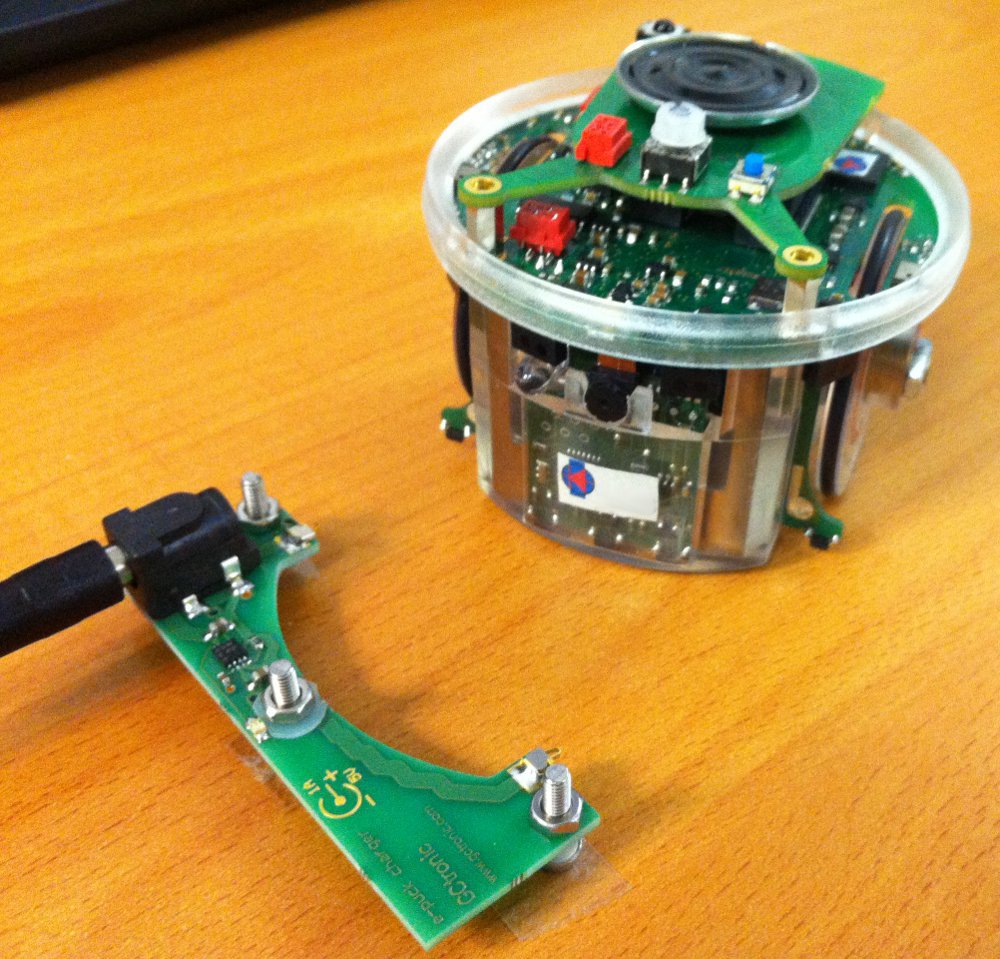
| In the package you'll find also an external power adapter that will be useful during development of your applications. As power supply you could use the one of the e-puck battery charger. The following figure shows the power supply cable, the external power cable and the extension.<br/>
| |
| <span class="plainlinks">[http://www.gctronic.com/doc/images/External-power.jpg <img width=400 src="http://www.gctronic.com/doc/images/External-power.jpg">]</span> <br/>
| |
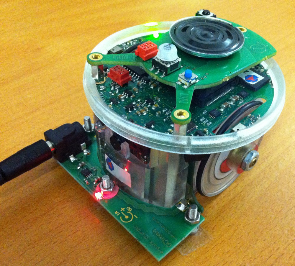
| You need to simply attach the power supply in one side, and the other side of the external power cable on top of the extension (near the USB plug). Once the cable is connected a green led should turn on indicating that the extension is running. <br/>
| |
| <span class="plainlinks">[http://www.gctronic.com/doc/images/External-power-attached.jpg <img width=400 src="http://www.gctronic.com/doc/images/External-power-attached.jpg">]</span> <br/>
| |
| The external power cable could also be plugged in when the extension is mounted on the e-puck, but '''<font style="color:red"> pay attention to not turn on the robot when the external cable supplies the energy, otherwise there could be serious damages of the devices and the battery</font>'''.
| |
| | |
| ==3.3V and 5V source==
| |
| The 3.3 V comes from the e-puck robot and the 5V comes from the gumstix extension. The gumstix extension can be used alone (without the robot attached to it) but some things are related to the 3.3 V thus without the robot connected they will not work; an example are the RGB leds of the omnivion module, that need the robot to be connected to the extension in order to be used.
| |
| | |
| =Software=
| |
| ==E-puck firmware==
| |
| <!-- The firmware that has to be uploaded on the e-puck when working with the extension for Gumstix Overo COM can be downloaded from [http://projects.gctronic.com/E-Puck/DemoGCtronic-gumstix/DemoGCtronic-gumstix.hex hex]; the related MPLAB project can also be downloaded from [http://projects.gctronic.com/E-Puck/DemoGCtronic-gumstix/DemoGCtronic-gumstix.zip MPLAB project]. -->
| |
| Refers to the section [http://www.gctronic.com/doc/index.php/E-Puck#Standard_firmware E-Puck Standard firmware] for the firmware that need to be uploaded to the robot. | | Refers to the section [http://www.gctronic.com/doc/index.php/E-Puck#Standard_firmware E-Puck Standard firmware] for the firmware that need to be uploaded to the robot. |
| Essentially in this firmware a new version of the ''advanced sercom'' is included (selector position 10) in which the bluetooth communication is replaced by the serial line communication, running at 230400 between robot and gumstix. Moreover the I2C is disabled temporary from the dsPIC side (the dsPIC cannot communicate through I2C) in order to avoid conflicts. As a last note, the body led and front led aren't anymore usable with the extension due to the two extra long range proximity sensors and for power saving purposes the motors are configured to the minimum energy consumption during movement.<br/> | | Essentially the standard ''asercom'' demo (selector 3) released with the e-puck robot is extended in order to request and visualize 5 sensors values instead of 3 when issueing the ''m'' command; the sequence is: ground left, ground center, ground right, cliff right, cliff left. In order to enable the cliff sensors you need to ''define CLIFF_SENSORS'' in the ''asercom.c'' file in order to build the code parts related to this module. |
| The values of the two extra proximity sensors can be retrieved with the command ''N'' in the ''advanced sercom'' (selector position 10); the last two values returned by the command refer to these proximity sensors (the others values refer to the proximity sensors mounted on the e-puck as usual).
| |
| | |
| ===Project building===
| |
| Refer to section [http://www.gctronic.com/doc/index.php/E-Puck#Project_building Project building] for information on how to build the project for the e-puck firmware.
| |
| | |
| ==Cross compilation==
| |
| If you want to develop some applications that will run on the gumstix you need to firstly download the toolchain.
| |
| | |
| If you're using Ubuntu you can simply type <code>sudo apt-get install gcc-arm-linux-gnueabi g++-arm-linux-gnueabi</code> to install the required toolchain (have a look at [http://www.gumstix.org/basic-cross-compilation.html http://www.gumstix.org/basic-cross-compilation.html] and [http://wiki.gumstix.org/index.php?title=Toolchain http://wiki.gumstix.org/index.php?title=Toolchain] for more information).
| |
| | |
| Alternatively when you need to handle external dependencies is better using the toolchain integrated in OpenEmbedded (${OVEROTOP}/tmp/cross or ${OVEROTOP}/tmp/sysroots/i686-linux/usr/armv7a/bin/ with recent version) if you have it in your system. For more information refers to the [http://wiki.gumstix.org/index.php?title=Category:How_to_-_OpenEmbedded gumstix wiki].<br/>
| |
| | |
| For other linux systems you can find a toolchain in the following link [http://www.mentor.com/embedded-software/sourcery-tools/sourcery-codebench/editions/lite-edition/ http://www.mentor.com/embedded-software/sourcery-tools/sourcery-codebench/editions/lite-edition/] (30 days trial); this toolchain is useful for small programs:
| |
| # download the Lite Edition, you'll have a file named something like ''arm-2009q3-67-arm-none-linux-gnueabi.bin''
| |
| # open a terminal, go to the directory of the file, type ''chmod +x arm-2009q3-67-arm-none-linux-gnueabi.bin'', after execute the file ''./arm-2009q3-67-arm-none-linux-gnueabi.bin'' to start the installation
| |
| # follow the installation steps; you have to choose where to install the toolchain, this is the path you will specify in the makefile
| |
| | |
| Once a toolchain is installed in the system the process will be simply something like this:
| |
| # develop your application as you do normally in your developing machine
| |
| # cross-compile in your developing machine using the tools previously downloaded
| |
| # copy the executable in the extension's micro SD and run it
| |
| You can download the [http://projects.gctronic.com/Gumstix/helloworld.zip hello world example] containing a makefile in which you have to specify the path to the toolchain you previously installed in order to build the program; you can use it for others programs.<br/>
| |
| Refer to section [http://www.gctronic.com/doc/index.php/Overo_Extension#Demos http://www.gctronic.com/doc/index.php/Overo_Extension#Demos] for some application examples.
| |
| | |
| Of course you can also install the compiler directly on the embedded system and build the applications from it, but the process will take longer due to limited computational power compared to a developing machine.
| |
| | |
| ===External dependencies===
| |
| Some applications may require external libraries not contained within the standard toolchain package. For instance if your application depends on ''libjpeg'' then you need to tell the cross-compiler where to look to find this library (compiled for the target machine) otherwise your application will not be compiled. If you have OpenEmbedded installed in your system you could simply bitbake the external dependencies (in our example ''bitbake jpeg'') and then compile your application. Instead if you rely on the CodeSourcery toolchain you need to follow these steps:
| |
| # download the sources of the library
| |
| # cross-compile the library
| |
| # install the library (and include files) in the right places
| |
| # compile your application
| |
| | |
| ==Ground sensor==
| |
| It's possible to use contemporaneously both the e-puck extension for gumstix overo and the ground sensor; in this case the camera and the ground sensor will share the same I2C bus and like the camera, also the ground sensor will not be anymore reachable from the e-puck side, but only from the overo side. <br/>
| |
| The I2C bus is configured to work at 400 KHz in the system running on the gumstix overo, thus we need to change the bus speed to 100 KHz in order to communicate with the ground sensor module; the simplest way is to set a kernel parameter in u-boot:
| |
| # enter u-boot by pressing any key at boot start
| |
| # type the command <code>setenv i2cspeed 3,100</code>; this init the I2C bus 3 to 100 KHz
| |
| # type the command <code>setenv mmcargs setenv bootargs console=${console} i2c_bus=${i2cspeed} ${optargs} mpurate=${mpurate} vram=${vram} omapfb.mode=dvi:${dvimode} omapdss.def_disp=${defaultdisplay} root=${mmcroot} rootfstype=${mmcrootfstype} </code>; basically we pass an additional parameter to the kernel that is the <code>i2c_bus=${i2cspeed}</code>
| |
| # type the command <code>saveenv</code> to save the environment changes
| |
| # type <code>boot</code> to start booting
| |
| Pay attention that all the peripherals connected to the bus will now work at 100 KHz, thus also the e-puck camera and the LSM330 (accelerometer + gyroscope) present with e-puck HwRev 1.3.<br/>
| |
| If you want to set back the bus speed to 400 KHz you need to follow steps 2-4, by setting the <code>i2cspeed</code> u-boot environment variable with <code>setenv i2cspeed 3,400</code>.<br/>
| |
| Communicating with the ground sensor is as easy as open a device and reading from it; a source code example can be found in the following link [http://projects.gctronic.com/Gumstix/groundsensor.c http://projects.gctronic.com/Gumstix/groundsensor.c]. You will find this application example in the <code>/home/root/demos/gumstix-common</code> directory; start it by executing <code>./i2c_groundsensors</code> and the sensors values will be displayed in the terminal.<br/>
| |
| Make sure that you have installed the last system update otherwise you'll encounter some problems.<br/>
| |
| You can find more information about the I2C and gumstix in the following links:
| |
| * [http://wiki.gumstix.org/index.php?title=I%C2%B2C http://wiki.gumstix.org/index.php?title=I%C2%B2C]
| |
| * [http://wiki.gumstix.org/index.php?title=Category:How_to_-_i2c http://wiki.gumstix.org/index.php?title=Category:How_to_-_i2c]
| |
| * [http://108.163.188.242/~jumpnowt/index.php?option=com_content&view=article&id=69&Itemid=78 http://108.163.188.242/~jumpnowt/index.php?option=com_content&view=article&id=69&Itemid=78]
| |
| <!--
| |
| ===Examples===
| |
| ====Images transfer (serial line)====
| |
| The application "transfer_images" running on the Gumstix Overo COM performs a request of a variable number of images to the e-puck and transfers them over either TCP or UDP to a server machine (a connection must be configured on both sides before running this program). For more information on the usage refers to the help (-h option). This demo works with the ''advanced sercom'' protocol, so the new e-puck firmware must be already charged and selector 10 must be chosen.<br/>
| |
| In order to compile the application the Makefile must be modified specifying the path to the cross-compiler (for more information on cross-compilation for the OMAP3530 processor refers to [http://focus.ti.com/docs/prod/folders/print/omap3503.html http://focus.ti.com/docs/prod/folders/print/omap3503.html]).
| |
| [[image:ImageReceiver.jpeg|thumb|Image receiver application.]]
| |
| The application "ImageReceiver" running on the server machine is used to visualize the images received from the e-puck. <br/>
| |
| The usage is very simple: the server listening port and the protocol must be first selected and then the button "Connect" clicked; at this moment the application is waiting images.
| |
| The application is a Qt project, so the compilation may be handled easily with [http://www.qtsoftware.com/products/developer-tools Qt Creator]; alternatively [http://doc.trolltech.com/4.2/qmake-manual.html qmake] can be used.
| |
| | |
| It's worth to note that the server application must be started before sending images, thus the "ImageReceiver" application must be first executed on the PC side, and the "transfer_images" application must be then executed on the Gumstix Overo side.
| |
| | |
| [http://www.gctronic.com/doc/images/Image_transfer.tar Download Transfer images (Linux)] <br/>
| |
| [http://www.gctronic.com/doc/images/Image_receiver.tar Download Image receiver (Linux)]
| |
| | |
| ====Images grabbing (serial line)====
| |
| This application, running on the Overo COM, requests to the e-puck a customizable number of images that can be parametrized by size, zoom factor, type (gray-scale or color) and window position and save them as bmp; for more information on the usage refers to the help (-h option). This demo works with the ''advanced sercom'' protocol, so the new e-puck firmware must be already charged and selector 10 must be chosen.<br/>
| |
| In order to compile the application the Makefile must be modified specifying the path to the cross-compiler like with the "Images transfer" application.
| |
| | |
| [http://www.gctronic.com/doc/images/GrabCustomImages.tar Download Grab custom images (Linux)]
| |
| | |
| -->
| |
| | |
| ==OpenCV==
| |
| The Open Computer Vision Library has more than 500 algorithms, documentation and sample code for real time computer vision; you can download it from [http://sourceforge.net/projects/opencvlibrary/ http://sourceforge.net/projects/opencvlibrary/], and find information about it from the official wiki [http://docs.opencv.org/index.html http://docs.opencv.org/index.html]. <br/>
| |
| The released system comes with OpenCV version 2.0.0 pre-installed and a demo that shows an example of what can be performed with this library. The demo let the robot follow a black filled circle placed in front of it; if the circle is moved right or left the robot turns consequently. The following figure shows an example of the circle detected by the robot:<br/>
| |
| <span class="plainlinks">[http://www.gctronic.com/doc/images/circle-detection.jpg <img width=200 src="http://www.gctronic.com/doc/images/circle-detection.jpg">]</span> <br/>
| |
| In order to start the demo follows these steps:
| |
| # turn on the robot with the gumstix extension and login as ''root'' with password ''root''
| |
| # go to the directory ''/home/root/demos/gumstix-common'' and execute ''./v4l2grab-opencv -o image.jpg''
| |
| # the demo should return the number of circles detected and save a resulting image showing the circles detected if any
| |
| Alternatively you can use the following script, that launches the demo and send it through serial (using zmodem) iteratively:
| |
| <pre>
| |
| #!/bin/bash
| |
| while true; do
| |
| ./v4l2grab-opencv -o image.jpg -q 50
| |
| lsz img1.jpg
| |
| done
| |
| </pre>
| |
| | |
| The source code can be downloaded from the following link [http://projects.gctronic.com/Gumstix/v4l2grab-opencv-rev15.zip v4l2grab-opencv.zip].
| |
| | |
| <!--
| |
| ====Opencv-linux 1.1pre1 version====
| |
| OpenCV can be easily installed on the Gumstix Overo COM, following these steps:
| |
| | |
| :1. [http://sourceforge.net/projects/opencvlibrary/ Donwload] OpenCV.
| |
| :2. Extract the content (tar -xzvf opencv-1.1pre1.tar.gz) of the file in a directory, let it be in "opencv".
| |
| :3. Open a terminal, and access the directory (cd path/to/opencv).
| |
| :4. Configure the environment in order to use the cross-compilation tools (if you installed OpenEmbedded, you can find these tools in /tmp/cross/bin/ within the OE main directory): <br/>
| |
| <pre>
| |
| export CC=/path_to_OE_home_dir/tmp/cross/bin/arm-angstrom-linux-gnueabi-gcc
| |
| export CXX=/path_to_OE_home_dir/tmp/cross/bin/arm-angstrom-linux-gnueabi-g++
| |
| </pre>
| |
| :5. Now configure OpenCV with the following command; in this configuration several packages are disabled (e.g. gtk) because useless when using console mode to work with the gumstix. Another important option is ''prefix'', which tell where the OpenCV library will be installed. For more information on the configuration refers to the help (--help).<br/>
| |
| <pre>
| |
| ./configure --host=arm-linux --build=i686-linux --prefix=/install_dir_path/ --without-gthread --without-gtk --without-python --disable-apps
| |
| </pre>
| |
| :6. Type ''make'' and then ''make install''; the directory specified with the ''prefix'' options will contain the compiled library.
| |
| :7. Copy the content of this directory to the gumstix, for example in an external SD card.
| |
| :8. Before trying to execute an OpenCV based application, you must specify to the system where to find the OpenCV library; you can do this by typing the following command; alternatively it's possible to install directly the library in the /usr/lib directory in the system.
| |
| <pre>
| |
| export LD_LIBRARY_PATH=/path_to_OpenCV/lib
| |
| </pre>
| |
| | |
| A detailed tutorial on the OpenCV setup for Gumstix can be found in the following link [http://danielbaggio.blogspot.com/2009/01/compiling-opencv-for-gumstix.html Compiling OpenCV for Gumstix].
| |
| | |
| ====Later versions (> 1.1)====
| |
| It's possible to have the OpenCV framework available on your system in two ways:
| |
| :1. if OpenEmbedded and bitbake are already configured in the system you can simply type ''bitbake opencv'' and then install the libraries on the micro-sd of the overo
| |
| :2. if you have internet access from the overo you can use the package manager by typing ''opkg install opencv'' (it takes a while to complete)
| |
| -->
| |
| | |
| <!--
| |
| Later versions of OpenCV (current is 2.0.0) rely on [http://www.cmake.org/ CMake], the cross-platform, open-source build system.You can install it in Ubuntu by typing ''sudo apt-get install cmake''; you can also install a nice front-end for CMake by typing ''sudo apt-get install cmake-gui''; in this way the configuration process of OpenCV becomes easier.<br>
| |
| Follow the steps afterwards to get the newer version of OpenCV compiled for the gumstix:
| |
| :1. [http://sourceforge.net/projects/opencvlibrary/ Donwload] OpenCV.
| |
| :2. Extract the content (tar -xzvf opencv-2.0.0.tar.gz) of the file in a directory, let it be in "opencv".
| |
| :3. Start the CMake interface, by typing in a terminal ''cmake-gui''.
| |
| :4. ...to be finished!
| |
| -->
| |
| | |
| ==Accelerometer and gyroscope (e-puck HWRev 1.3)==
| |
| When the e-puck extension for gumstix overo is mounted on the e-puck hardware revision 1.3 the same I2C bus is shared by all the devices (camera, accelerometer, gyroscope) and the overo; since there is only one master (the overo) these devices will not be anymore reachable from the e-puck side. <br/>
| |
| The I2C bus is configured to work at 400 KHz in the system running on the gumstix overo and this is fine to work with the accelerometer and gyroscope. <br/>
| |
| Communicating with the accelerometer and gyroscope is as easy as open a device and reading from it; a source code example can be found in the following link [http://projects.gctronic.com/Gumstix/i2c_lsm330.c i2c_lsm330.c]. You will find this application example in the <code>/home/root/demos/gumstix-common</code> directory; start it by executing <code>./i2c_lsm330</code>, type <code>0</code> to get the accelerometer values or <code>1</code> to get the gyroscope values printed on the terminal.<br/>
| |
| The values of the accelerometer and gyroscope read from the gumstix through the I2C are 16 bits (1g = 16384); beware that regarding the accelerometer values there is a mismatch between the values read from the gumstix through I2C and the values read from the [{{fullurl:Advanced sercom protocol}} advanced sercom protocol] through Bluetooth, the latter are converted in the firmware to maintain compatibility with older e-puck hardware revisions.<br/>
| |
| The orientation of the accelerometer for the values read from the gumstix through the I2C is also different from the one used in the e-puck firmware; the orientation is shown below, the x axis points forward, the y axis points left and the z axis points upward:<br/>
| |
| <span class="plainlinks">[http://www.gctronic.com/doc/images/epuck-acc-directions1.3.png <img width=150 src="http://www.gctronic.com/doc/images/epuck-acc-directions1.3.png">]</span><br/>
| |
| ===Python===
| |
| An example in python is available from the following link [http://projects.gctronic.com/Gumstix/i2c_lsm330.py i2c_lsm330.py]. In order to run the script, some additional dependencies need to be installed in the system, follow these steps:
| |
| # configure the network in order to have internet access
| |
| # update the package manager repos:
| |
| ##<code>echo 'src/gz base http://feeds.angstrom-distribution.org/feeds/v2012.12/ipk/eglibc/armv7a-vfp-neon/base/' > /etc/opkg/base-feed.conf</code>
| |
| ##<code>echo 'src/gz python http://feeds.angstrom-distribution.org/feeds/v2012.12/ipk/eglibc/armv7a-vfp-neon/python/' > /etc/opkg/python-feed.conf</code>
| |
| # add <code>arch armv7a-vfp-neon 45</code> to the file <code>/etc/opkg/arch.conf</code>
| |
| # <code>opkg update</code>
| |
| # <code>opkg -force-overwrite install python-smbus</code>
| |
| # optionally you can also remove some warnings related to the update by running the following script [http://projects.gctronic.com/omnicam/remove-warnings.sh remove-warnings.sh]
| |
| Once the system is configured you can start the script by executing <code>python i2c_lsm330.py</code>, type <code>0</code> to get the accelerometer values or <code>1</code> to get the gyroscope values printed on the terminal.<br/>
| |
| | |
| ==ROS==
| |
| We tested ROS on the gumstix extension with the Yocto system. Follow these steps to get ROS running on the e-puck extension:
| |
| :1. prepare a micro sd following the instructions from [http://gumstix.org/create-a-bootable-microsd-card.html http://gumstix.org/create-a-bootable-microsd-card.html]
| |
| :2. download the file system and fat from the following links: [http://projects.gctronic.com/Gumstix/yocto-ros-3.5.7-FAT.tar.gz yocto-ros-3.5.7-FAT.tar.gz], [http://projects.gctronic.com/Gumstix/yocto-ros-3.5.7-rootfs.tar.gz yocto-ros-3.5.7-rootfs.tar.gz]
| |
| :3. login with user=root and empty password
| |
| :4. issue the following commands to enable the WiFi dongle:
| |
| ::<code>echo host > /sys/bus/platform/devices/musb-hdrc/mode</code>
| |
| ::<code>echo -n 1 > /sys/bus/usb/devices/2-1/bConfigurationValue</code>
| |
| :5. follow the instructions from [https://github.com/gumstix/yocto-manifest/wiki/ROS-on-Gumstix#the-fun-part https://github.com/gumstix/yocto-manifest/wiki/ROS-on-Gumstix#the-fun-part] to run a demo
| |
| <!--
| |
| We tested ROS on the gumstix extension with the Yocto pre-built system. Follow these steps to get ROS running on the e-puck extension:
| |
| :1. download the Yocto pre-built image from [https://www.gumstix.com/software/software-downloads/ https://www.gumstix.com/software/software-downloads/] (Overo Series COMs)
| |
| :2. prepare a micro sd following the instructions from [http://gumstix.org/create-a-bootable-microsd-card.html http://gumstix.org/create-a-bootable-microsd-card.html]
| |
| :3. configure the network settings in order to get internet access (at the moment you need to plug the WiFi dongle on the USB host)
| |
| :4. follow the instructions from [https://github.com/gumstix/yocto-manifest/wiki/ROS-on-Gumstix#one-time-on-system-setup https://github.com/gumstix/yocto-manifest/wiki/ROS-on-Gumstix#one-time-on-system-setup] (skip step 1)
| |
| If you prefer you can directly download the file system and fat from the following links: [http://projects.gctronic.com/Gumstix/yocto-ros-3.5.7-FAT.tar.gz yocto-ros-3.5.7-FAT.tar.gz], [http://projects.gctronic.com/Gumstix/yocto-ros-3.5.7-rootfs.tar.gz yocto-ros-3.5.7-rootfs.tar.gz].
| |
| -->
| |
| | |
| ==Python==
| |
| In order to install python 2.6 on the e-puck extension for Gumstix follow these steps:
| |
| # download the package [http://projects.gctronic.com/Gumstix/python-gumstix.tar.gz python-gumstix.tar.gz]
| |
| # extract the package: <code>tar -zxvf python-gumstix.tar.gz</code>
| |
| # remove the micro sd from the robot and connect it to your computer; two partitions will be opened, one called <code>FAT</code> and the other called <code>overo</code> containing the file system (the partitions name could be a little different)
| |
| # copy the content of the decompressed file to the same position in the <code>overo</code> partition:
| |
| ##<code>sudo cp -R /python-gumstix/usr/lib/* /overo/usr/lib</code>
| |
| ##<code>sudo cp /python-gumstix/usr/bin/* /overo/usr/bin</code>
| |
| | |
| Alternatively if you have access to internet you can use the package manager:
| |
| # <code>opkg install python</code>
| |
| # <code>opkg install python-modules</code>
| |
| # <code>opkg install python-pyserial</code>
| |
| | |
| In order to test your python installation you can download the following script [http://projects.gctronic.com/Gumstix/printhelp.py printhelp.py]; execute it by typing <code>python printhelp.py</code>.
| |
| This is a minimal example of serial communication in python that let the gumstix communicate with the robot; basically it opens a serial connection with the robot and ask the available commands that you can use to get sensors data and change actuators state.<br/>
| |
| Another example is available here [http://projects.gctronic.com/Gumstix/getprox.py getprox.py]; in this script the values of the proximities are requested to the robot and printed to the console. The data are requested in binary format, for more information about the communication protocol refer to the section [http://www.gctronic.com/doc/index.php/Overo_Extension#Advanced_sercom advanced sercom].
| |
| | |
| =Configuration=
| |
| ==Graphic mode==
| |
| The resolution of the monitor can be modified in the u-boot command line, that can be entered at booting. In the u-boot command line type:
| |
| <pre>
| |
| setenv dvimode "1280x720MR-16@60"
| |
| saveenv
| |
| boot
| |
| </pre>
| |
| Now the configuration is saved in the flash; if your monitor doesn't support the current resolution, repeat the procedure with a different configuration (change the resolution numbers).
| |
| | |
| Note that the DVI Controller ([http://projects.gctronic.com/Gumstix/tfp410.pdf TFP410]) mounted on Summit and Tobi supports resolutions from VGA (640x480) to UXGA (1600x1200).
| |
| | |
| Useful files to look at:
| |
| * linux_source_home/drivers/video/modedb.c: explains what's the mean of the dvimode names
| |
| * linux_source_home/Documentation/fb/viafb.modes: list of available modes usable with the ''fbset'' tool
| |
| | |
| ==GPIO - pins mode==
| |
| There are three different ways to read GPIO lines:
| |
| :1. Kernel space: GPIO lines handled through an API
| |
| :2. User space:
| |
| ::2.1. standard filesystem commands like ''cat'' and ''echo'' (static configuration)
| |
| ::2.2 direct physical memory access using ''devmem2'' or with a C application (dynamic configuration)
| |
| | |
| Afterward will be explained how to handle the GPIO lines on the Gumstix Overo COM in all different methods; information about this topic were found from various sites, but especially from the [http://sourceforge.net/p/gumstix/mailman/ mailing list]. Moreover for a general howto on GPIO refers to the linux documentation [https://www.kernel.org/doc/Documentation/gpio/gpio.txt "KernelSrc/Documentation/gpio.txt"].
| |
| | |
| ===Kernel space===
| |
| | |
| ===User space===
| |
| ====Static configuration====
| |
| Each of the microprocessor IO pins can be configured to work in different ways for different purposes; in case we desire a certain pin to be configured as a gpio line, we must modify the function assigned to that pin (mux configuration) in the U-Boot board configuration file, that for the Gumstix Overo COM is located at "U-BootSrc/board/overo/overo.h". <!-- you can have a look at it [http://www.sakoman.net/cgi-bin/gitweb.cgi?p=u-boot-omap3.git;a=blob;f=board/overo/overo.h;h=4c7ac27fa6818d4f474bc42330134fd0a5520a37;hb=HEAD here].--> <br/>
| |
| | |
| To know which modes are available for the pins consult the chapter ''7-System Control Module'' (more specifically ''7.4.4-Pad Functional Multiplexing and Configuration'') in the [http://projects.gctronic.com/Gumstix/omap35xx-TRM.pdf OMAP35x TRM]. <br/>
| |
| | |
| Assume we want to have the possibility to switch on and off a led attached to the line gpio70; in order to accomplish this task, we need to follow these steps:
| |
| | |
| :'''1.''' Modify the board configuration file "overo.h" specifying that the pin has to behave as a gpio line:
| |
| <pre>
| |
| MUX_VAL(CP(DSS_DATA0), (IDIS | PTU | DIS | M4)) /*DSS_DATA0 => GPIO70*/\
| |
| </pre>
| |
| :*IDIS = input disable, namely output pin
| |
| :*PTU = pull type up, but could be also PTD (pull type down) because of the third parameter
| |
| :*DIS = disable pull type up/down
| |
| :*M4 = mode 4 (gpio)
| |
| :This give us a GPIO pin that is output and not pulled up or down.
| |
| :'''2.''' Build U-Boot and place the generated ''u-boot.bin'' image in the flash ([http://www.gumstix.org/how-to/70-writing-images-to-flash.html Writing images to onboard nand]) or in a micro sd card ([http://www.gumstix.org/create-a-bootable-microsd-card.html Creating a bootable microSD card])
| |
| :'''3.''' After login, we can see all the GPIO pins that have been exported by the kernel to userspace in the /sys/class/gpio/ directory. In order to access the gpio70 line, we should export it first, by typing:
| |
| <pre>
| |
| echo "70" > /sys/class/gpio/export
| |
| </pre>
| |
| :Now the following line is active /sys/class/gpio/gpio70.
| |
| :'''4.''' At this point we must configure the direction of the exported line and set a logical value (1 or 0) to that line, we can do that by typing:
| |
| <pre>
| |
| echo "high" > /sys/class/gpio/gpio70/direction
| |
| </pre>
| |
| :This command set the pin in output and give it a value of 1.
| |
| :'''5.''' Finally we can switch on or off the led, by setting the value of the gpio line:
| |
| <pre>
| |
| echo "value" > /sys/class/gpio/gpio70/value
| |
| </pre>
| |
| :Where value=1 means switch on, and value=0 means switch off.
| |
| | |
| | |
| In order to automate the process of creating a gpio line accessible through "/sys/class/gpio/", we must modify the board configuration file in the kernel source; this file can be found in "KernelSrc/arch/arm/mach-omap2/board-overo.c" (and related definitions in "KernelSrc/arch/arm/plat-omap/include/mach/board-overo.h"). These files must contain instructions to initialize the gpio line that we want to export in user space and set their direction and initial value. <br/>
| |
| Consider the previous example in which we would like to control a led with the gpio70 pin; for this purpose the following instructions must be added in the board configuration file ''board.overo.c'' within the ''overo_init'' function:
| |
| <pre>
| |
| if ((gpio_request(70, "OVERO_GPIO_DD00") == 0) && (gpio_direction_output(70, 1) == 0)) {
| |
| gpio_export(70, 0);
| |
| gpio_set_value(70, 1); //not really needed, the initial output value is set with gpio_direction_output
| |
| } else {
| |
| printk(KERN_ERR "could not obtain gpio for OVERO_GPIO_DD00\n");
| |
| }
| |
| </pre>
| |
| After this modification we need to build the kernel and copy it to the flash or micro sd card, and after login we will have the /sys/class/gpio/gpio70 line automatically active.<br/>
| |
| For more information on the previous snippet code refers to [https://www.kernel.org/doc/Documentation/gpio/gpio.txt "KernelSrc/Documentation/gpio.txt"].
| |
| | |
| <!--
| |
| Read a value
| |
| Set a pin in input
| |
| -->
| |
| | |
| ====Dynamic configuration====
| |
| If you aren't familiar with modifying and building U-Boot and kernel, you would probably choose to modify the pin configuration at runtime, without the need to touch any board configuration file. The only way to change the configuration of the pins is to access directly the physical memory of the microprocessor, in particular its configuration registers. <br/>
| |
| The utility [http://buildroot.uclibc.org/downloads/sources/devmem2.c devmem2] allows for easy reading and writing of the memory; after building and installing this utility on the Gumstix Overo COM, you are ready to change the ports functionality. Consider the previous example of the led on gpio70, to change the pin mode to gpio you must issue the following command:
| |
| <pre>
| |
| devmem2 0x480020DC b 0x14
| |
| </pre>
| |
| ''0x480020DC'' is the address of the register we want to write to and can be found observing the table 7-4 on chapter 7.4.4.3 of the [http://projects.gctronic.com/Gumstix/omap35xx-TRM.pdf OMAP35x TRM]; ''b'' means we want to write a byte to that register and finally ''0x14'' is the value we want to write. The pin mode depends on the last three bits, in this case the mode is set to 4, namely the pin is a gpio. From now on we can follow steps from 3 to 5 of the previous chapter to switch on and off the led.
| |
| | |
| An example on modifying the pins configuration through the C programming language can be found in the following link [http://docwiki.gumstix.org/index.php?title=Sample_code/C/gpregs gpregs.c].
| |
| | |
| ===Useful links/resources===
| |
| For more information on GPIO usage, have a look at the following links:
| |
| * [https://www.kernel.org/doc/Documentation/gpio/gpio.txt "KernelSrc/Documentation/gpio.txt"]
| |
| * [http://sourceforge.net/p/gumstix/mailman/ gumstix mailing list]
| |
| * [http://wiki.gumstix.org/index.php?title=GPIO http://wiki.gumstix.org/index.php?title=GPIO]
| |
| * [http://www.avrfreaks.net/wiki/index.php/Documentation:Linux/GPIO http://www.avrfreaks.net/wiki/index.php/Documentation:Linux/GPIO]
| |
| * [http://www.hy-research.com/omap3_pinmux.html http://www.hy-research.com/omap3_pinmux.html]
| |
| * [http://focus.ti.com/docs/prod/folders/print/omap3530.html http://focus.ti.com/docs/prod/folders/print/omap3530.html]
| |
| * [http://pixhawk.ethz.ch/omap/start http://pixhawk.ethz.ch/omap/start]
| |
| * [http://docs.blackfin.uclinux.org/doku.php?id=gpio http://docs.blackfin.uclinux.org/doku.php?id=gpio]
| |
| | |
| <!--
| |
| ==U-Boot==
| |
| You can find the U-Boot source at "git://gitorious.org/u-boot-omap3/mainline.git" or "http://git.gitorious.org/u-boot-omap3/mainline.git".
| |
| -->
| |
| | |
| =Webots interface=
| |
| Nikola Velickovic developed an interface with the Webots simulator during his MSc Thesis in 2012.
| |
| His report is available [http://projects.gctronic.com/Gumstix/MScThesis_NikolaVelickovic_2012.tar.gz here].
| |
| His files are available [http://projects.gctronic.com/Gumstix/ThesisProjectFiles(30.12.2011).tar.gz here].
| |
| | |
| =FAQ=
| |
| '''1. Why the serial communication between Gumstix Overo COM and the robot doesn't work?''' <br/>
| |
| There could be three possible reasons for the communication problem:
| |
| * selector position incorrect: you need to be sure that the robot selector is in position 10 in order to start the right software on the robot side
| |
| * wrong device: the serial device is identified as /dev/ttyS0 in the linux machine, be sure to use it when you're using for example the sertest demo ("./sertest -p /dev/ttyS0 -b 230400")
| |
| * battery discharged: somebody could be deceived from the fact that the linux console is still usable, but if the orange led on the robot indicating the low battery level is turned on, then the robot will not be able anymore to respond, even if you are working on the linux console; either change or charge your battery and try again. <br/>
| |
| | |
| '''2. I am able to communicate with the robot through the serial line, but seems that I receive only garbage, why?''' <br/>
| |
| Probably the baudrate isn't correct; with the robot selector in position 10 you need to configure the baudrate at 230400 (e.g "./sertest -p /dev/ttyS0 -b 230400"). <br/>
| |
|
| |
|
| '''3. Can I use bluetooth to connect to the robot? Can I use the [http://www.gctronic.com/doc/index.php/E-Puck#PC_interface monitor]?''' <br/>
| | ===e-puck demos=== |
| Yes, you can connect to the robot with bluetooth and play with the monitor interface placing the selector in position 3. You'll experience some errors on the values displayed on the monitor due to the additional two long IR sensors that aren't considered when the interface was developed; moreover you will not be able to receive images from the robot. <br/>
| | To demonstrate the capabilities of the cliff sensors module here is an MPLAB project [https://projects.gctronic.com/cliff-sensor/Demo-cliff-autocharge.zip Demo-cliff-autocharge.zip] that contains two demos: |
| | * selector 0: in this demo the robot is eventually piloted to the charger station autonomously after moving around for some time aovoiding obstacles; the demo is shown in the [http://www.gctronic.com/doc/index.php/Others_Extensions#Videos video section].<br/> |
| | * selector 1: this is a cliff avoidance demo in which the robot is moved forward until it detects the end of the table and tries to avoid it moving back and rotating; the demo is shown in the [http://www.gctronic.com/doc/index.php/Others_Extensions#Videos video section]. |
|
| |
|
| '''4. Why I cannot connect to the robot through SSH? <br/>
| | ===Extension firmware=== |
| * first of all be sure that the network is well configured (you can i.e. ping the robot sucessfully)
| | The ground sensor fimrware developed at EPFL (can be downloaded at the [http://www.e-puck.org http://www.e-puck.org] site from [http://www.e-puck.org/index.php?option=com_phocadownload&view=category&id=9:ground-sensors&Itemid=38 this page]) was extended to interact with the additional two sensors. The source code can be downloaded from [https://projects.gctronic.com/cliff-sensor/pic18_floor_sensor_c18-cliff.zip cliff-firmware]; it is an MPLAB project and the MPLAB C Compiler for PIC18 MCUs is needed to build the project.<br/> |
| * check the SSH daemon is running typing: ''ps -ef | grep sshd''; if it is not running then setup the SSH daemon to run automatically at boot; for this purpose you can type ''update-rc.d sshd defaults 99''. This command will install the links to ''sshd'' into rc*.d dirs. See the man page for more informations.
| | The communication between the e-puck and the module is handled through I2C (address 0xC0) and the following registers are defined: |
| * if the SSH server is running, but you get an error like "ssh: connect to host 192.168.1.2 port 22: Connection refused" when trying to connect, you can check whether a user and group sshd are created. If not, add the following entries in the system:
| | * 0x00: reflected light, left IR sensor - high byte |
| <pre>
| | * 0x01: reflected light, left IR sensor - low byte |
| /etc/group:sshd:*:27:
| | * 0x02: reflected light, center IR sensor - high byte |
| /etc/passwd:sshd:*:27:27:sshd privsep:/var/empty:/sbin/nologin
| | * 0x03: reflected light, center IR sensor - low byte |
| </pre>
| | * 0x04: reflected light, right IR sensor - high byte |
| | * 0x05: reflected light, right IR sensor - low byte |
| | * 0x06: ambient light, left IR sensor - high byte |
| | * 0x07: ambient light, left IR sensor - low byte |
| | * 0x08: ambient light, center IR sensor - high byte |
| | * 0x09: ambient light, center IR sensor - low byte |
| | * 0x0A: ambient light, right IR sensor - high byte |
| | * 0x0B: ambient light, right IR sensor - low byte |
| | * 0x0C: software revision number |
| | * 0x0D: reflected light, right cliff sensor - high byte |
| | * 0x0E: reflected light, right cliff sensor - low byte |
| | * 0x0F: reflected light, left cliff sensor - high byte |
| | * 0x10: reflected light, left cliff sensor - low byte |
| | * 0x11: ambient light, right cliff sensor - high byte |
| | * 0x12: ambient light, right cliff sensor - low byte |
| | * 0x13: ambient light, left cliff sensor - high byte |
| | * 0x14: ambient light, left cliff sensor - low byte |
|
| |
|
| '''5. How to auto-login and execute applications automatically at startup? <br/>
| | ===e-puck2 demos=== |
| Refers to the instructions explained here [https://wiki.gumstix.com/index.php/AutoLogin https://wiki.gumstix.com/index.php/AutoLogin].
| | The same demo developed for the e-puck1 that let the robot autonomously reach the charging station and charge itself is available also for the e-puck2. You can find the source code in the following repository [https://github.com/e-puck2/e-puck2_cliff_autocharge https://github.com/e-puck2/e-puck2_cliff_autocharge]. |
|
| |
|
| '''6. Are micro SDHC supported? <br/>
| | ==Images== |
| Yes they are supported.
| | Robot equipped with the cliff sensor: <br/> |
| | <span class="plainlinks">[http://www.gctronic.com/doc/images/Cliff+charger.jpg <img width=300 src="http://www.gctronic.com/doc/images/Cliff+charger.jpg">]</span> <br/> |
|
| |
|
| =Videos=
| | The robot can be easily moved to the charging station as shown in the following figure: <br/> |
| <!--{{#ev:youtube|LQC9lvn9w8Q}} | | <span class="plainlinks">[http://www.gctronic.com/doc/images/Cliff-charging.jpg <img width=300 src="http://www.gctronic.com/doc/images/Cliff-charging.jpg">]</span> <br/> |
| Comments:
| |
| We have sent an e-puck on a mission to find our office plant.
| |
| It's actually a standard e-puck with a wifi connection to the laptop and the Gumstix's overo extention with Linux OS, all runned by a powerful 0.6 Ghz processor. -->
| |
|
| |
|
| {{#ev:youtube|a0Ozy-oRQIs}} <br/>
| | The following figure shows the two additional sensors (near the wheels) mounted on the cliff module and the three frontal sensors of the ground module: <br/> |
| Comments: This e-puck is on an exploration, his camera sends continuous image to the computer with a wifi connection.
| | <span class="plainlinks">[http://www.gctronic.com/doc/images/Cliff-zoom.jpg <img width=300 src="http://www.gctronic.com/doc/images/Cliff-zoom.jpg">]</span> <br/> |
|
| |
|
| =Useful links= | | ==Videos== |
| [http://www.gumstix.org/ http://www.gumstix.org/] <br/>
| | {{#ev:youtube|7iFmLBng3qg}} |
| [http://wiki.gumstix.org/index.php?title=Main_Page http://wiki.gumstix.org/index.php?title=Main_Page] <br/>
| | {{#ev:youtube|NYOcb1QoUTM}} |
| [http://docwiki.gumstix.org/index.php/Gumstix_Buildroot_Support_Wiki http://docwiki.gumstix.org/index.php/Gumstix_Buildroot_Support_Wiki] <br/>
| |
| [http://docwiki.gumstix.org/index.php?title=U-Boot http://docwiki.gumstix.org/index.php?title=U-Boot] <br/>
| |
| [http://www.openembedded.org/wiki/Main_Page http://www.openembedded.org/wiki/Main_Page] <br/>
| |
| [http://www.e-puck.org/ http://www.e-puck.org/] <br/>
| |
| [http://www.jumpnowtek.com/ http://www.jumpnowtek.com/] <br/>
| |