|
|
| Line 1: |
Line 1: |
| [{{fullurl:e-puck2}} e-puck2 main wiki]<br/> | | =Range and bearing= |
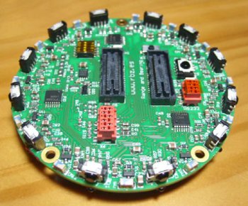
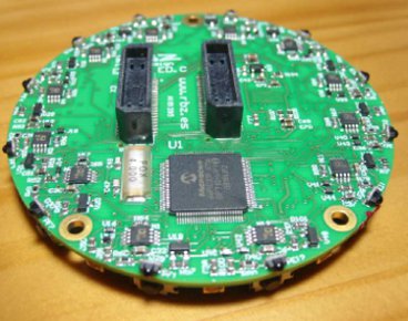
| =Introduction= | | <span class="plainlinks">[http://www.gctronic.com/doc/images/randb-1-small.jpg <img height=150 src="http://www.gctronic.com/doc/images/randb-1.jpg">][http://www.gctronic.com/doc/images/randb-2-small.jpg <img height=150 src="http://www.gctronic.com/doc/images/randb-2.jpg">]</span><br/> |
| The <code>C programming</code> language is used to develop code for the main microcontroller of the e-puck2 robot. The [http://www.chibios.org ChibiOS] embedded real-time OS was chosen to be integrated in the firmware, since it support the STM32F4 family of microprocessors, it includes an HAL (Hardware Abstraction Layer), it's well documented and finally it's free.<br>
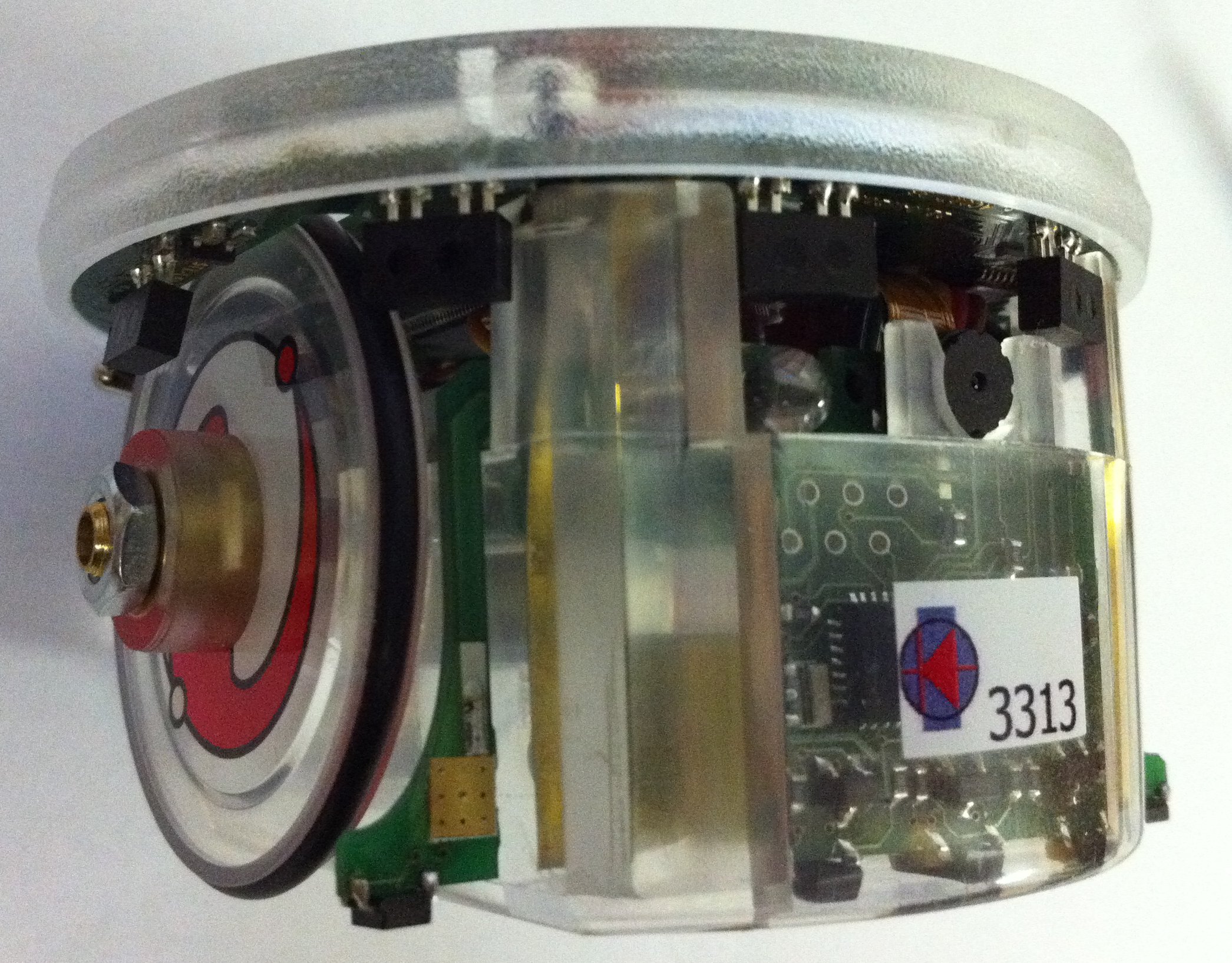
| | The board allows situated agents to communicate locally, obtaining at the same time both the range and the bearing of the emitter without the need of any centralized control or any external reference. Therefore, the board allows the robots to have an embodied, decentralized and scalable communication system. The system relies on infrared communications with frequency modulation and is composed of two interconnected modules for data and power measurement.<br/> |
| Before starting to code, you need to install the developing environment and its dependencies, all the steps are documented afterwards.<br>
| |
| The factory firmware integrates both the e-puck2 library used to handle all the sensors and actuators together with a series of demos that use this library. Thus you can either take the factory firmware and directly modify its main, otherwise you can start a fresh new project by linking the factory firmware project as an external library.<br>
| |
| You can also modify the library itself, but before digging into the details, try to contact us, maybe we're already working on that subject or we can help you.
| |
|
| |
|
| =Installation of the e-puck2 environment=
| | The documentation and hardware files are available in the following links: |
| <code>Eclipse_e-puck2</code> is a distribution of Eclipse IDE for C/C++ Developers specially modified to edit and compile e-puck2's projects out of the box. It doesn't require to be installed and everything needed is located in the package given. The only dependency needed to be able to run Eclipse is '''Java'''.
| | * [https://projects.gctronic.com/randb/eRandB_Ed.D_Schematics.pdf Schematics (pdf)] |
| | * [https://projects.gctronic.com/randb/eRandB_Ed.D_Assembling.pdf Assembling (pdf)] |
| | * [https://projects.gctronic.com/randb/eRandB_Ed.D_BillOfMaterials.xls Bill of Materials (xls)] |
| | * [https://projects.gctronic.com/randb/eRandB_Ed.D_PCB.pdf PCB (pdf)] |
| | * [https://projects.gctronic.com/randb/eRandB_Ed.D_HardwareSourceFiles.zip Hardware source files(zip)] |
| | * [https://projects.gctronic.com/randb/eRandB_Ed.D_Fabrication.zip Fabrication: Gerber, pick and place, ... (zip)] |
| | * [https://projects.gctronic.com/randb/eRandB_manual.pdf e-RandB manual (pdf)] |
| | * [https://projects.gctronic.com/randb/eRandB_firmware.zip e-RandB firmware (zip)] |
| | * [https://projects.gctronic.com/randb/eRandB_software.tgz e-puck software and examples (tgz)] |
|
| |
|
| ==Installation for Windows==
| | You can find more information about this board in the following links: [http://www.e-puck.org/index.php?option=com_content&view=article&id=35&Itemid=23 http://www.e-puck.org/index.php?option=com_content&view=article&id=35&Itemid=23]. |
| ===Java 8 32bits===
| |
| This section can be ignored if Java version >= 8 32bits is already installed on your computer.<br>
| |
| To verify you already installed Java, you can open <code>Programs and Features</code> from the <code>control panel</code> and search for a <code>AdoptOpenJDK JDK with Hotspot xxx</code> install. If this entry isn't present, then you need to install it:
| |
| # Go to [https://adoptopenjdk.net/releases.html OpenJDK download page] and download the <code>OpenJDK 8 (LTS) HotSpot for Windows x86 JDK</code> (take the installer, aka. <code>.msi</code> file).
| |
| # Run the downloaded installer and follow its instructions to proceed with the installation of OpenJDK 32bits.
| |
| :<span class="plain links">[https://projects.gctronic.com/epuck2/wiki_images/openjdk-windows.png <img width=700 src="https://projects.gctronic.com/epuck2/wiki_images/openjdk-windows.png">]</span><br/>
| |
| :''OpenJDK download page''
| |
|
| |
|
| ===Eclipse_e-puck2=== | | The following table lists the I2C the registers map: |
| #Download the [https://github.com/e-puck2/Create_Eclipse_e-puck2/releases/download/29_jan_2020/Eclipse_e-puck2_Win32_29_jan_2020.zip Eclipse_e-puck2 package for windows].
| | <blockquote> |
| #Unzip the downloaded file to the location you want (can take time). It is strongly recommended for better performance and less extraction time to use 7Zip. You can download it on http://www.7-zip.org.
| | {| border="1" cellpadding="10" cellspacing="0" |
| #You can now run the <code>Eclipse_e-puck2.exe</code> to launch Eclipse.
| | !Address !!Read !!Write |
| #You can create a shortcut to <code>Eclipse_e-puck2.exe</code> and place it anywhere if you want.
| | |- |
| | |0 || 1 if data available, 0 otherwise || - |
| | |- |
| | |1 || data MSB || - |
| | |- |
| | |2 || data LSB || - |
| | |- |
| | |3 || bearing MSB || - |
| | |- |
| | |4 || bearing LSB: <code>double((MSB<<8)+LSB)*0.0001</code> to get angle in degrees|| - |
| | |- |
| | |5 || range MSB || - |
| | |- |
| | |6 || range LSB || - |
| | |- |
| | |7 || max peak (adc reading) MSB || - |
| | |- |
| | |8 || max peak (adc reading) LSB || - |
| | |- |
| | |9 || sensor that received the data (between 0..11) || - |
| | |- |
| | |12 || - || Set transmission power (communication range): between 0 (max range) and 255 (min range) |
| | |- |
| | |13 || - || data LSB (prepare) |
| | |- |
| | |14 || - || data MSB (send <code>(MSB<<8)+LSB</code>) |
| | |- |
| | |16 || - || 0 store light conditions (calibration) |
| | |- |
| | |17 || - || 1=onboard calculation, 0=host calculation |
| | |- |
| | |} |
| | </blockquote> |
|
| |
|
| :<span class="plain links">[https://projects.gctronic.com/epuck2/wiki_images/Eclipse_e-puck2_Folder_Windows.png <img width=800 src="https://projects.gctronic.com/epuck2/wiki_images/Eclipse_e-puck2_Folder_Windows.png">]</span><br/>
| | ==Firmware source code== |
| :''Eclipse_e-puck2 folder obtained after extraction''
| |
|
| |
|
| '''Important things to avoid :'''
| |
| :1. The path to the <code>Eclipse_e-puck2</code> folder must contain zero space.
| |
| ::Example :
| |
| ::<code>C:\epfl_stuff\Eclipse_e-puck2</code> OK
| |
| ::<code>C:\epfl stuff\Eclipse_e-puck2</code> NOT OK
| |
| :2. You must not put <code>Eclipse_e-puck2</code> folder into <code>Program Files (x86)</code>. Otherwise the compilation when using Eclipse will not work.
| |
| :3. The file’s structure in the <code>Eclipse_e-puck2</code> folder must remain the same. It means no file inside this folder must be moved to another place.
| |
|
| |
|
| ===Configuring the PATH variable=== | | ==e-puck 1== |
| The <code>PATH</code> variable is an environment variable used to store a list of the paths to the folders containing the executables we can then run in a terminal from any path.
| | A simple [https://projects.gctronic.com/randb/test-eRandB.zip MPLAB project] was created to let start using these modules. With the selector it's possible to choose whether the robot is an emitter (selector in position 0) or a receiver (selector in position 1). The receiver will send the information (data, bearing, distance, sensor) through Bluetooth. |
|
| |
|
| If you want to use the <code>arm-none-eabi</code> toolchain provided inside the <code>Eclipse_e-puck2</code> package, you have to add it to the <code>PATH</code> variable to be able to call it inside a terminal window. To set the <code>PATH</code> variable you need to issue the following command:
| | ==e-puck 2== |
| | The e-puck2 standard firmware contains a demo example to use the range and bearing extension. When the selector is in position 4 then the robot is the receiver, when in position 5 then the robot is the transmitter. The receiver will print (you need to connect the USB cable and open the USB serial port) the data received, the bearing, the distance and the sensor id; while the transmitter will send continously <code>0xAAFF</code>.<br/> |
| | You can download the pre-built firmware from [https://projects.gctronic.com/epuck2/e-puck2_main-processor_randb.elf e-puck2_main-processor_randb.elf]; the source code is available form the repo [https://github.com/e-puck2/e-puck2_main-processor https://github.com/e-puck2/e-puck2_main-processor].<br/> |
| | Beware that the only communication channel available between the robot and the range and bearing extension is the I2C bus, the UART channel is not available with e-puck 2. |
|
| |
|
| <code>set PATH=your_installation_path\Eclipse_e-puck2\Tools\gcc-arm-none-eabi-7-2017-q4-major-win32\bin;%PATH%</code> | | =Ground sensors= |
| | <span class="plainlinks">[http://www.gctronic.com/doc/images/E-puck-groundsensors.jpg <img width=200 src="http://www.gctronic.com/doc/images/E-puck-groundsensors.jpg">]</span> |
|
| |
|
| What is important to know is that this procedure is temporary. It applies only to the terminal window used to type it. If you open a new terminal window or close this one, you will have to set again the <code>PATH</code> variable.
| | The factory firmware of both the e-puck1 and e-puck2 supports the ground sensors extension: for e-puck1 refer to the section [https://www.gctronic.com/doc/index.php?title=E-Puck#Standard_firmware Standard firmware], for e-puck2 refer to section [https://www.gctronic.com/doc/index.php?title=e-puck2#Factory_firmware Factory firmware]. |
|
| |
|
| If you want to set the <code>PATH</code> variable permanently, then go to <code>Control panel</code> => <code>System</code> => <code>Advanced system settings</code> => <code>Environment variables</code>. A list of variables defined for the user is shown, double click on the <code>PATH</code> variable (from the user variables list) and add at the end <code>;your_installation_path\Eclipse_e-puck2\Tools\gcc-arm-none-eabi-7-2017-q4-major-win32\bin</code>, then click <code>OK</code> three times.
| | Once the robot is programmed with its factory firmware, you can get the values from the ground sensors through Bluetooth by putting the selector in position 3 and issueing the command <code>m</code> that will return 5 values, the first 3 values are related to the ground sensors (left, center, right), the last 2 values are related to the cliff extension (if available).<br/> |
| | For more information about the Bluetooth connection refer to section [https://www.gctronic.com/doc/index.php?title=E-Puck#Getting_started Getting started] (e-puck1) or [https://www.gctronic.com/doc/index.php?title=e-puck2_PC_side_development#Connecting_to_the_Bluetooth Connecting to the Bluetooth] (e-puck2).<br/> |
| | For more information about the Bluetooth protocol refer to section [https://www.gctronic.com/doc/index.php?title=Advanced_sercom_protocol Advanced sercom protocol]. |
|
| |
|
| Note : The <code>arm-none-eabi</code> version can differ from the one given in this example. It could be needed to adapt the path to the correct version.
| | If you couple the e-puck extension for Gumstix Overo with the ground sensor refer to the section [http://www.gctronic.com/doc/index.php/Overo_Extension#Ground_sensor http://www.gctronic.com/doc/index.php/Overo_Extension#Ground_sensor] to have an example on how to read the sensor values. |
|
| |
|
| ==Installation for Linux== | | You can find more information about the ground sensors extension module in the following link [http://www.e-puck.org/index.php?option=com_content&view=article&id=17&Itemid=18 http://www.e-puck.org/index.php?option=com_content&view=article&id=17&Itemid=18].<br/> |
| ===Java 8=== | |
| This section can be ignored if Java is already installed on your computer.<br>
| |
| To verify whether it is installed or not you can type the following command into a terminal window: <code>update-java-alternatives -l</code>. If Java is installed, you will get some information about it, otherwise the command will be unknown.<br>
| |
| You need to have <code>Java 1.8.xxxx</code> listed to be able to run <code>Eclipse_e-puck2</code>.
| |
|
| |
|
| Type the following commands in a terminal session to install Java SDK:
| | ==Assembly for e-puck2== |
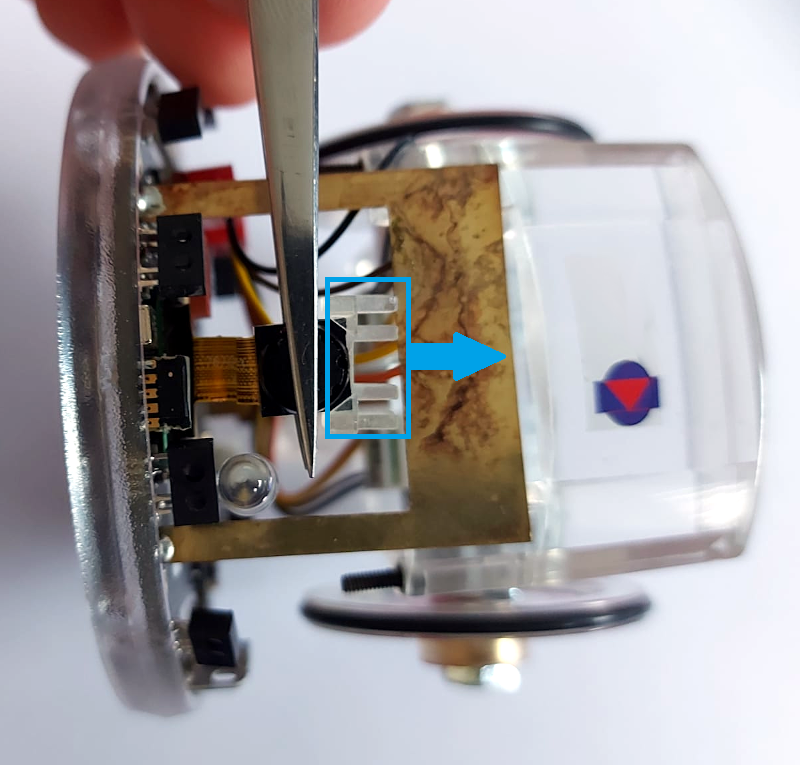
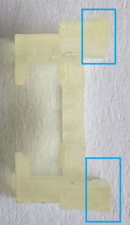
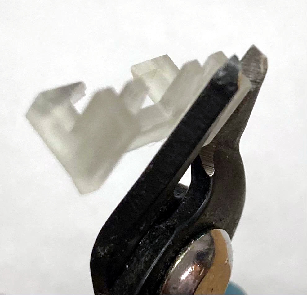
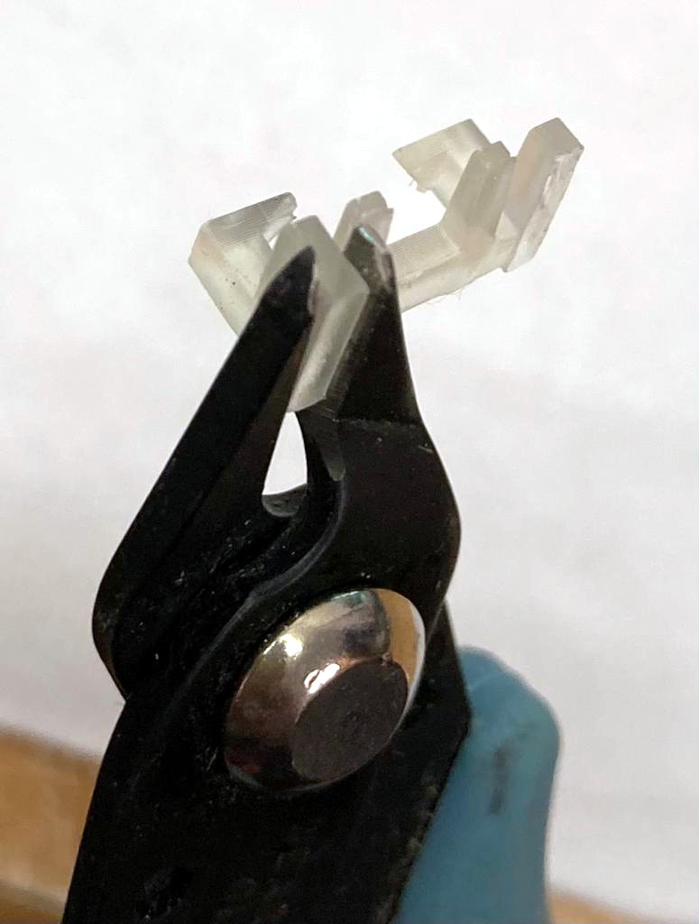
| <pre>sudo add-apt-repository ppa:openjdk-r/ppa | | <span class="plainlinks"><table><tr><td align="center">[1]</td><td align="center">[2]</td><td align="center">[3.1]</td><td align="center">[3.2]</td><td align="center">[3.3]</td><td align="center">[3.4]</td></tr><tr><td align="center">[https://projects.gctronic.com/epuck2/wiki_images/ground-assembly-1.png <img height=200 src="https://projects.gctronic.com/epuck2/wiki_images/ground-assembly-1_small.png">]</td><td align="center">[https://projects.gctronic.com/epuck2/wiki_images/ground-assembly-2.png <img height=200 src="https://projects.gctronic.com/epuck2/wiki_images/ground-assembly-2_small.png">]</td><td align="center">[https://projects.gctronic.com/epuck2/wiki_images/ground-assembly-3.1.png <img height=200 src="https://projects.gctronic.com/epuck2/wiki_images/ground-assembly-3.1_small.png">]</td><td align="center">[https://projects.gctronic.com/epuck2/wiki_images/ground-assembly-3.2.png <img height=200 src="https://projects.gctronic.com/epuck2/wiki_images/ground-assembly-3.2.png">]</td><td align="center">[https://projects.gctronic.com/epuck2/wiki_images/ground-assembly-3.3.jpeg <img height=200 src="https://projects.gctronic.com/epuck2/wiki_images/ground-assembly-3.3_small.jpeg">][https://projects.gctronic.com/epuck2/wiki_images/ground-assembly-3.4.jpeg <img height=200 src="https://projects.gctronic.com/epuck2/wiki_images/ground-assembly-3.4_small.jpeg">]</td><td align="center">[https://projects.gctronic.com/epuck2/wiki_images/ground-assembly-3.5.png <img height=200 src="https://projects.gctronic.com/epuck2/wiki_images/ground-assembly-3.5.png">]</td></tr><tr><td align="center">[4]</td><td align="center">[5.1]</td><td align="center">[5.2]</td><td align="center">[5.3]</td><td align="center">[5.4]</td><td align="center">[6]</td></tr><tr><td align="center">[https://projects.gctronic.com/epuck2/wiki_images/ground-assembly-4.png <img height=200 src="https://projects.gctronic.com/epuck2/wiki_images/ground-assembly-4_small.png">]</td><td align="center">[https://projects.gctronic.com/epuck2/wiki_images/ground-assembly-5.1.png <img height=200 src="https://projects.gctronic.com/epuck2/wiki_images/ground-assembly-5.1_small.png">]</td><td align="center">[https://projects.gctronic.com/epuck2/wiki_images/ground-assembly-5.2.png <img height=200 src="https://projects.gctronic.com/epuck2/wiki_images/ground-assembly-5.2_small.png">]</td><td align="center">[https://projects.gctronic.com/epuck2/wiki_images/ground-assembly-5.3.png <img height=200 src="https://projects.gctronic.com/epuck2/wiki_images/ground-assembly-5.3_small.png">]</td><td align="center">[https://projects.gctronic.com/epuck2/wiki_images/ground-assembly-5.4.png <img height=200 src="https://projects.gctronic.com/epuck2/wiki_images/ground-assembly-5.4_small.png">]</td><td align="center">[https://projects.gctronic.com/epuck2/wiki_images/ground-assembly-6.png <img height=200 src="https://projects.gctronic.com/epuck2/wiki_images/ground-assembly-6_small.png">]</td></tr></table></span> |
| sudo apt-get update
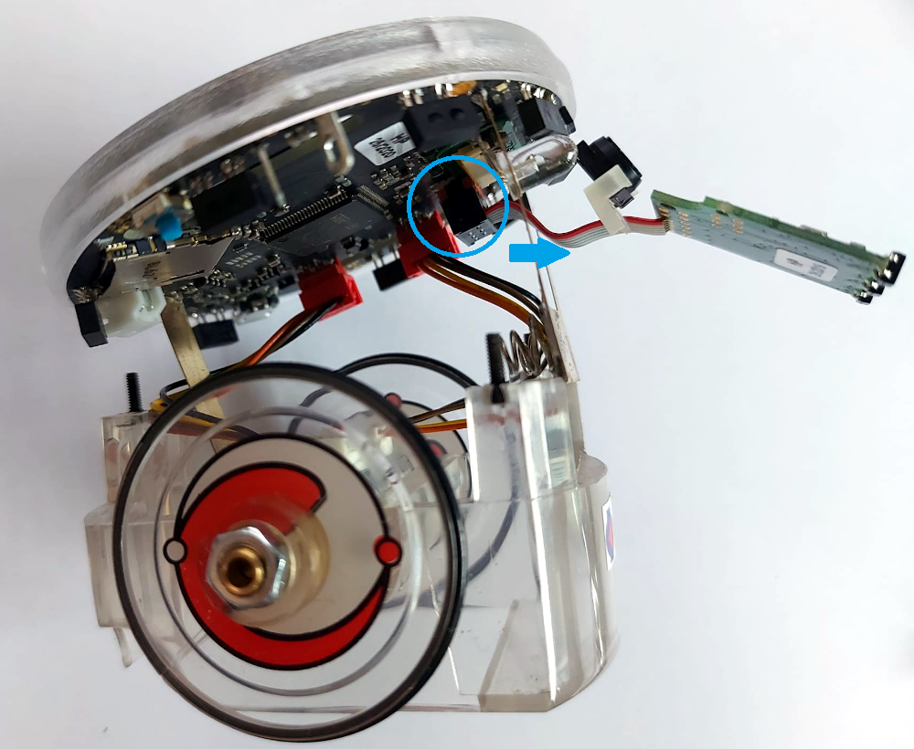
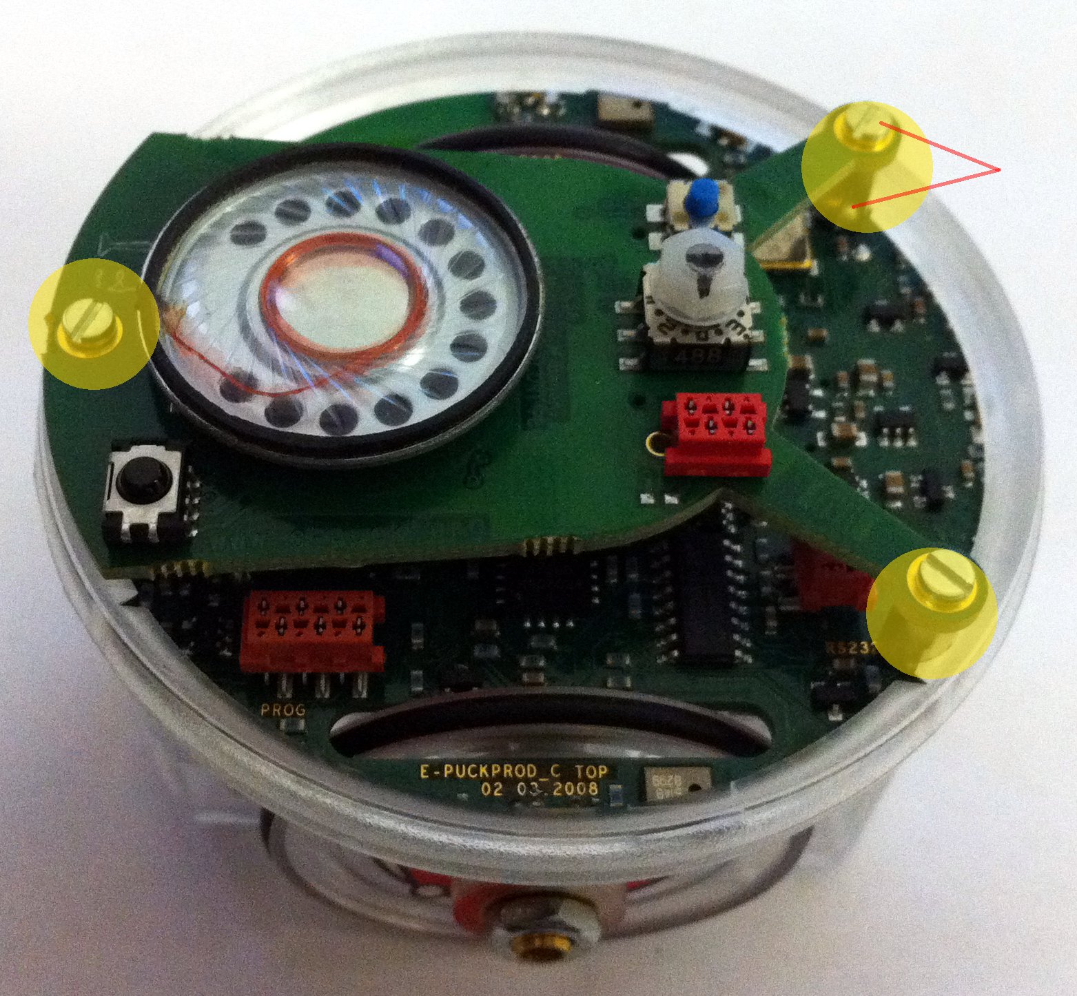
| | # Unscrew the 3 spacers and remove the battery. |
| sudo apt-get install openjdk-8-jre </pre>
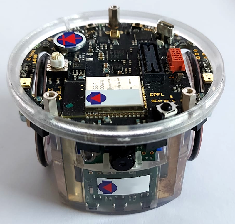
| | # Remove the top side from the case body gently. |
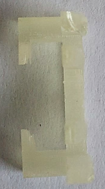
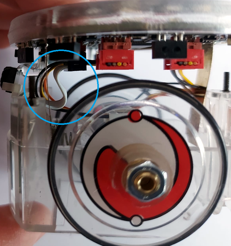
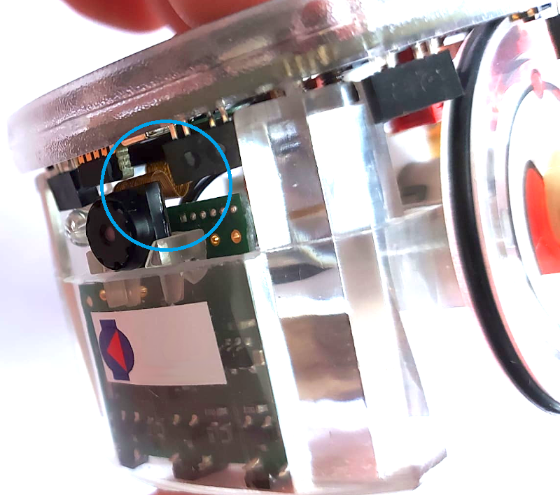
| | # Detach the plastic camera adapter from the camera with the help of pliers; be careful to not stress the camera flex cable. Then you need to cut off the two protruding pieces (see 3.2) on the back of the plastic adapter; for this operation you can use nippers (see 3.3). Take the adapter (now is flat on the back as shown in 3.4) and insert it as before. |
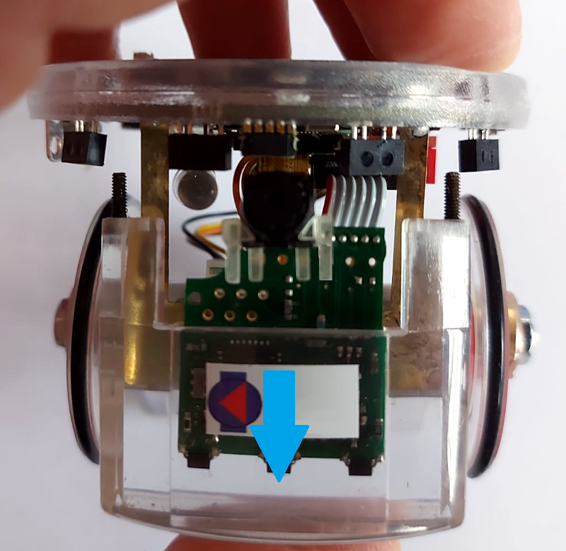
| | # Plug the ground module into its connector on the e-puck2; make the cable pass through the battery contact. |
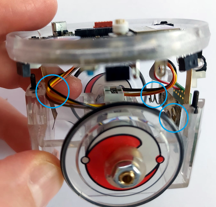
| | # First push the ground module within its slot in the body case, then slide in also the top side of the robot paying attention to the motors wires position: the back battery contact must remain between the body and motors wires and make sure the wires aren't stuck in the springs. Both the ground cable and camera flex cable must bend forming an "S" shape. |
| | # Push the top all way down, then remount the spacers and plug in the battery. You're done. |
|
| |
|
| ===Eclipse_e-puck2=== | | =Cliff sensor= |
| #Install <code>make</code> (probably you already have it installed) by issueing the command: <code>sudo apt-get install make</code>
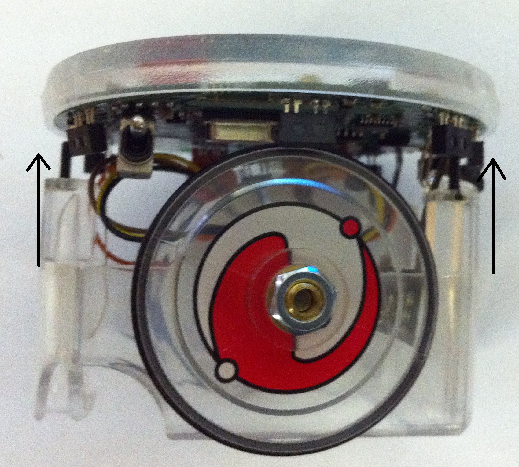
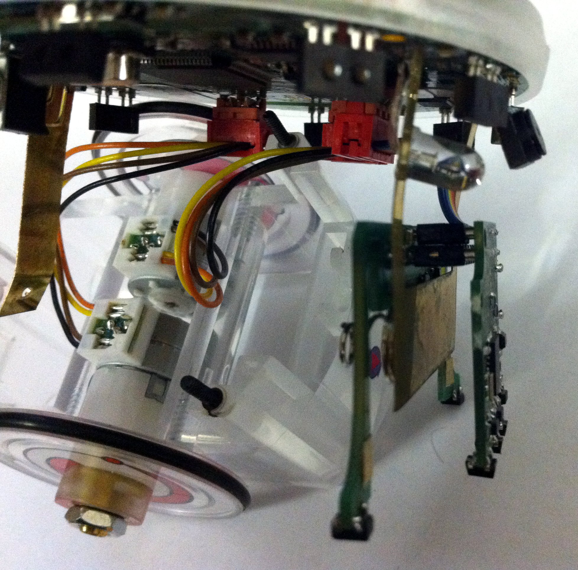
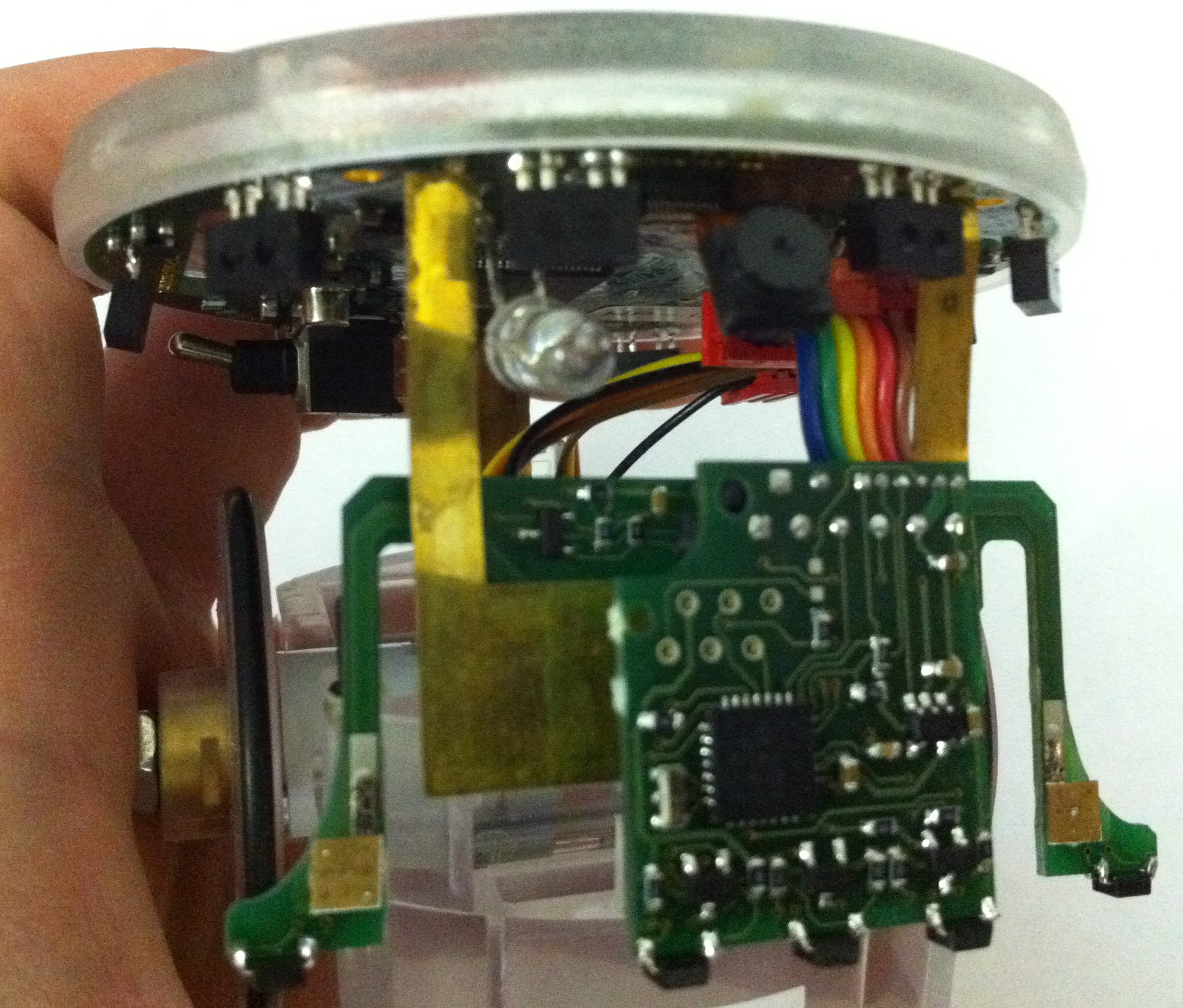
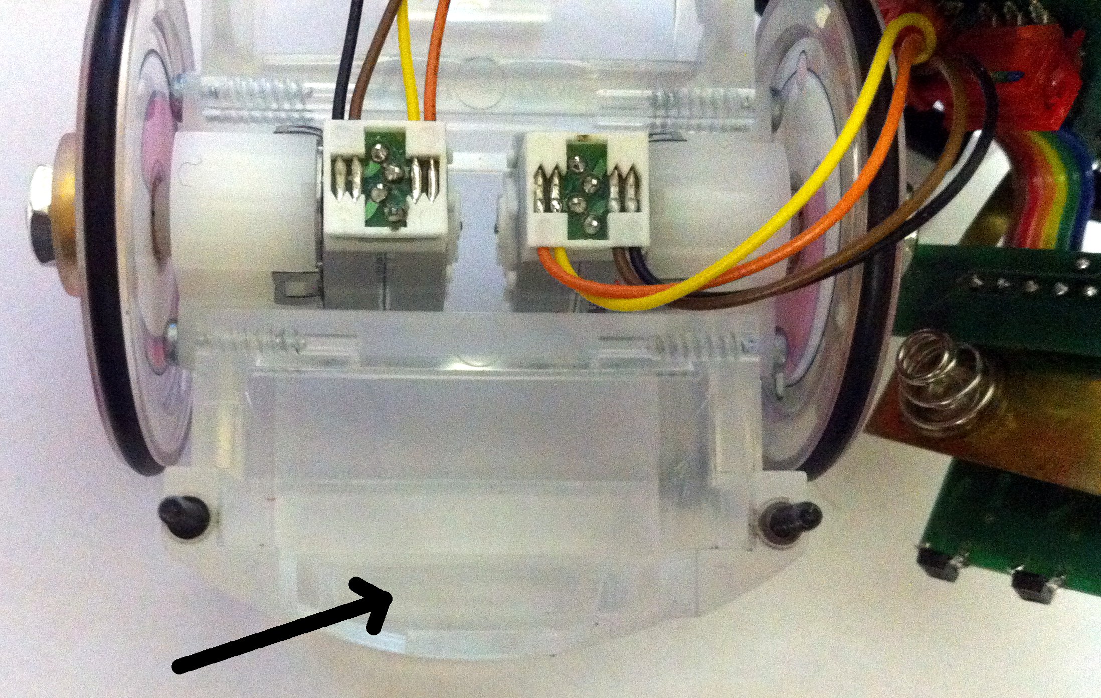
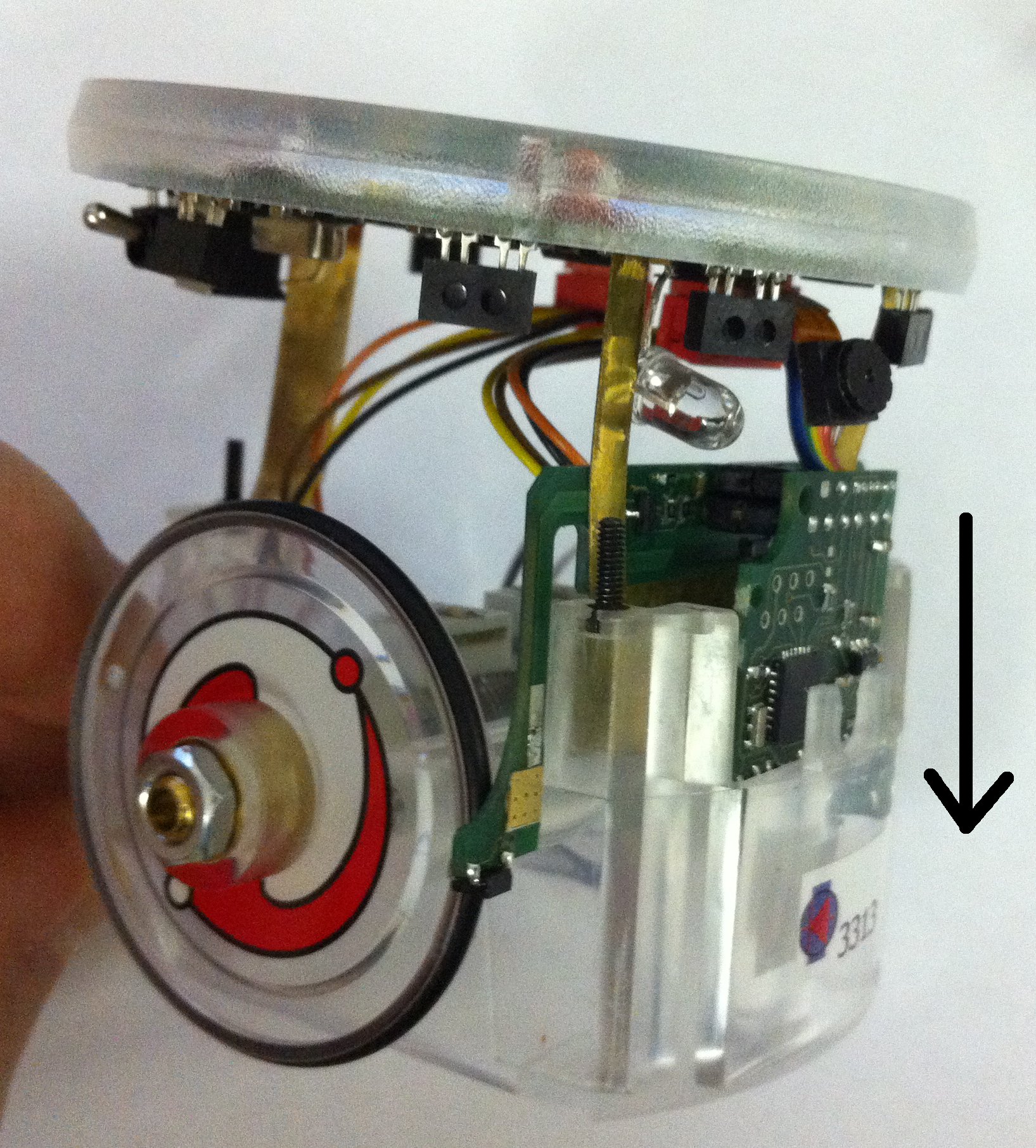
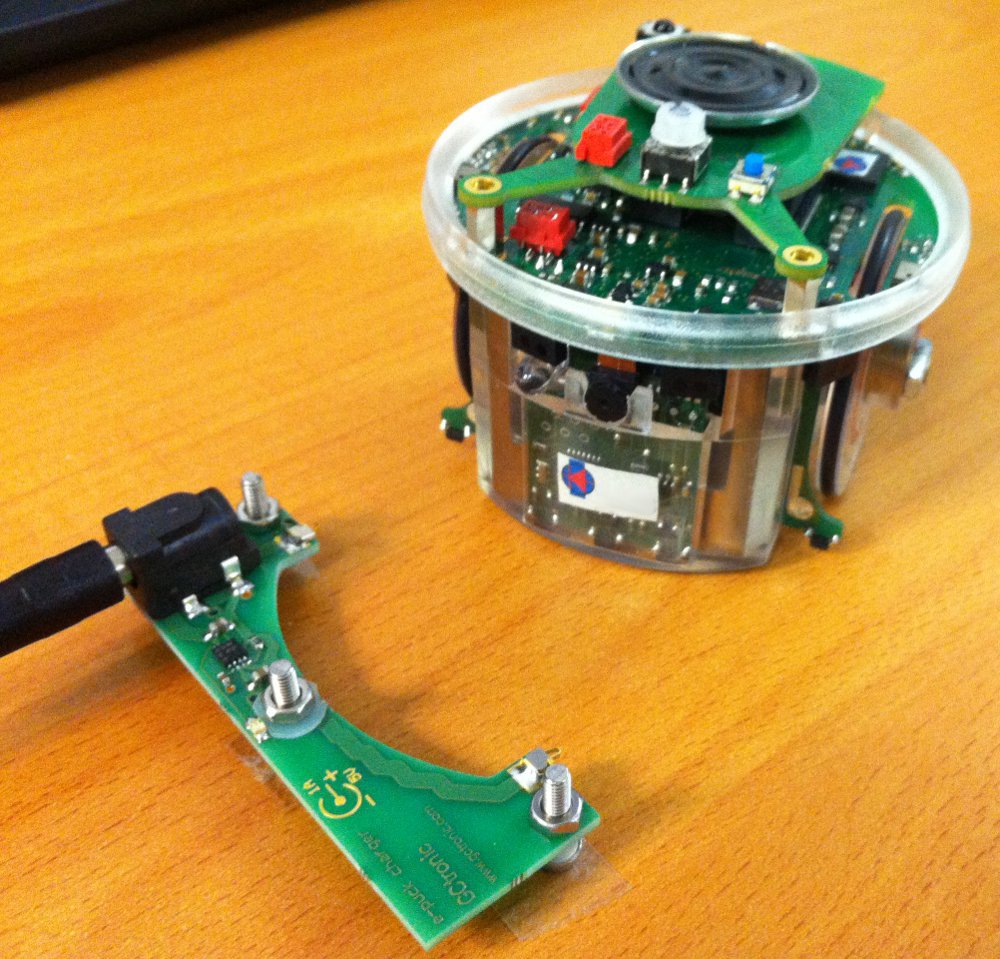
| | The cliff module extends the capability of the groundsensor with two additional sensors placed in front of the wheels. One possible application is that the e-puck can now detect the end of a table and react accordingly. Moreover this module can be coupled with the automatic charger for the e-puck, that could let the robot autonomously charge itself when needed. The two spring contacts adapt only to the cliff module. |
| #Download the Eclipse_e-puck2 package for Linux [https://projects.gctronic.com/epuck2/Eclipse_e-puck2/Eclipse_e-puck2_Linux_11_apr_2018_32bits.tar.gz 32bits] / [https://github.com/e-puck2/Create_Eclipse_e-puck2/releases/download/14_aug_2020/Eclipse_e-puck2_Linux64_14_aug_2020.tar.xz 64bits]. Pay attention to the 32bits or 64bits version. If unsure which Linux version you have, enter the following comand <code>uname -a</code> in the terminal window and look for <code>i686</code> (32bit) or <code>x86_64</code> (64 bit).
| |
| #Extract the downloaded file to the location you want (can take time): <code>tar -zxvf package_name.tar.gz</code>
| |
| #You can now run the <code>Eclipse_e-puck2</code> executable to launch Eclipse.
| |
|
| |
|
| :<span class="plain links">[https://projects.gctronic.com/epuck2/wiki_images/Eclipse_e-puck2_Folder_Linux.png <img width=800 src="https://projects.gctronic.com/epuck2/wiki_images/Eclipse_e-puck2_Folder_Linux.png">]</span><br/>
| | ==Assembly== |
| :''Eclipse_e-puck2 folder obtained after extraction''
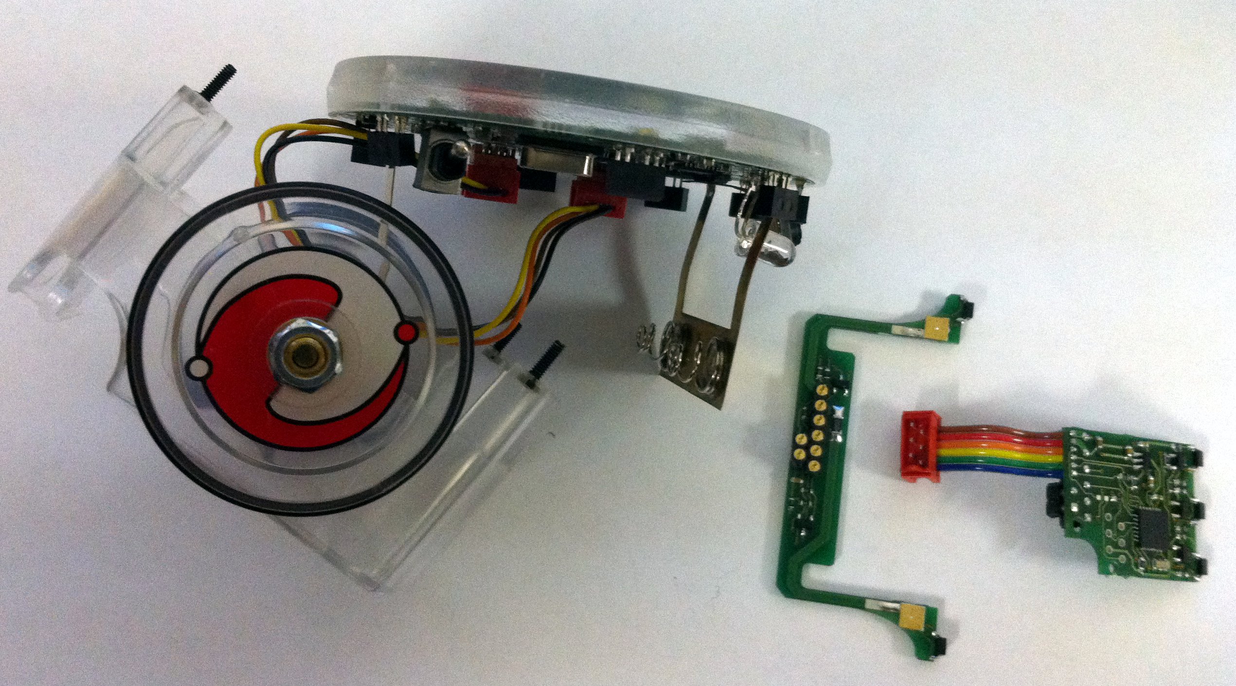
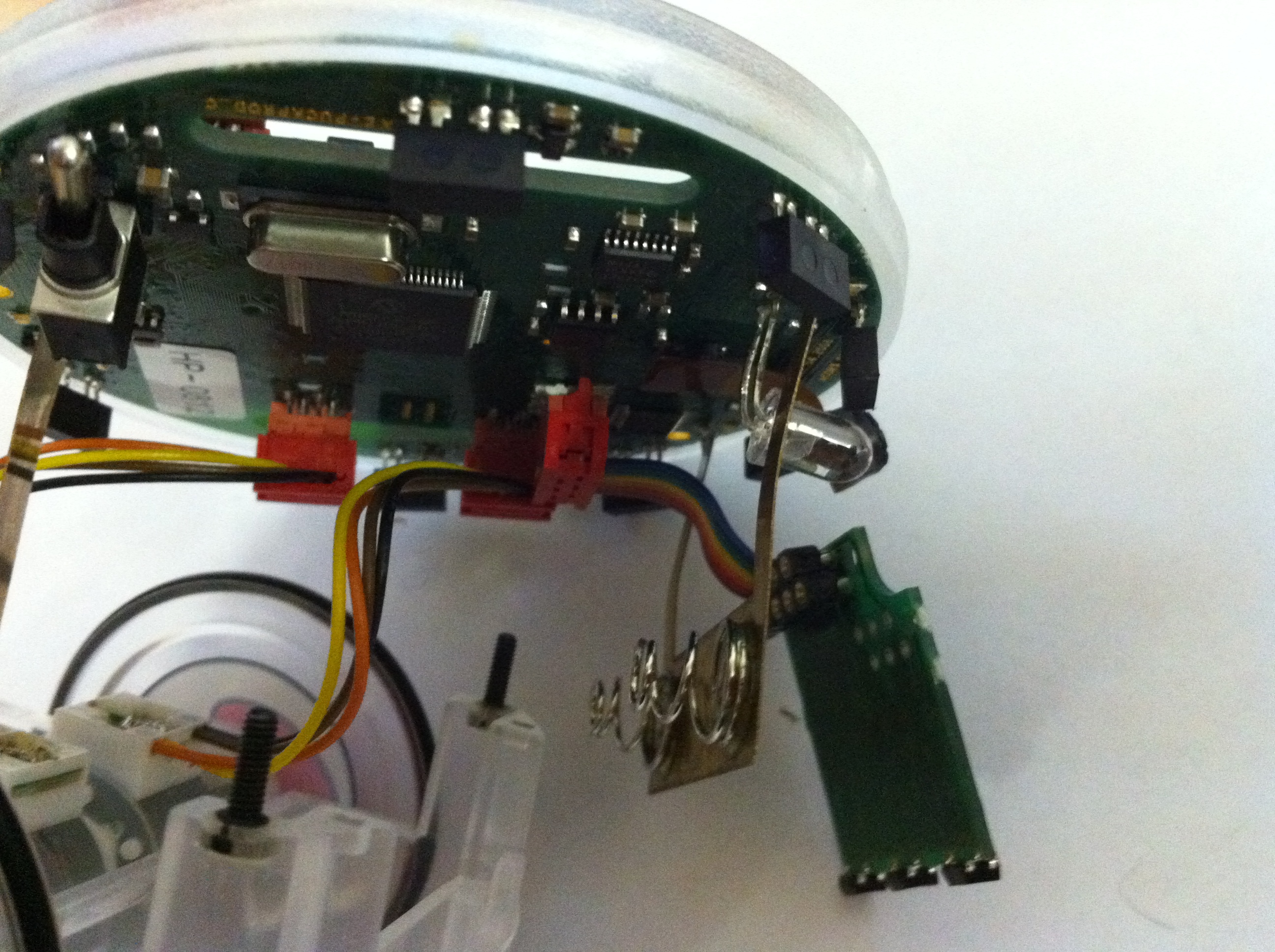
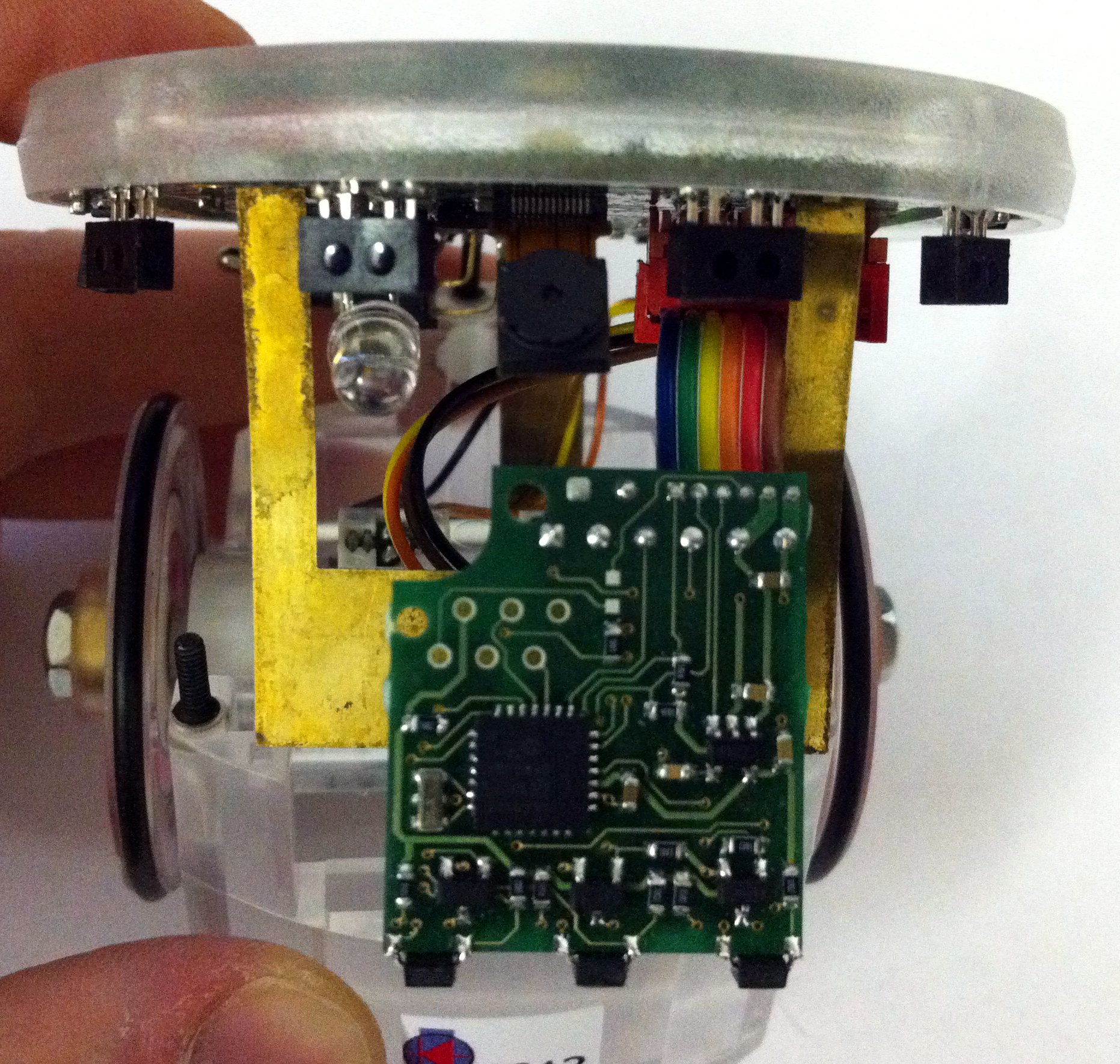
| | <span class="plainlinks"><table><tr><td align="center">[1]</td><td align="center">[2]</td><td align="center">[3]</td><td align="center">[4.1]</td><td align="center">[4.2]</td></tr><tr><td>[http://www.gctronic.com/doc/images/cliff-mounting-1.jpg <img height=200 src="http://www.gctronic.com/doc/images/cliff-mounting-1-small.jpg">]</td><td>[http://www.gctronic.com/doc/images/cliff-mounting-2.jpg <img height=200 src="http://www.gctronic.com/doc/images/cliff-mounting-2-small.jpg">]</td><td>[http://www.gctronic.com/doc/images/cliff-mounting-3.jpg <img height=200 src="http://www.gctronic.com/doc/images/cliff-mounting-3-small.jpg">]</td><td>[http://www.gctronic.com/doc/images/cliff-mounting-4-1.jpg <img height=200 src="http://www.gctronic.com/doc/images/cliff-mounting-4-1-small.jpg">]</td><td>[http://www.gctronic.com/doc/images/cliff-mounting-4-2.jpg <img height=200 src="http://www.gctronic.com/doc/images/cliff-mounting-4-2-small.jpg">]</td></tr><tr><td align="center">[5.1]</td><td align="center">[5.2]</td><td align="center">[6]</td><td align="center">[7]</td><td align="center">[8]</td></tr><tr><td>[http://www.gctronic.com/doc/images/cliff-mounting-5-1.jpg <img height=200 src="http://www.gctronic.com/doc/images/cliff-mounting-5-1-small.jpg">]</td><td>[http://www.gctronic.com/doc/images/cliff-mounting-5-2.jpg <img height=200 src="http://www.gctronic.com/doc/images/cliff-mounting-5-2-small.jpg">]</td><td>[http://www.gctronic.com/doc/images/cliff-mounting-6.jpg <img height=200 src="http://www.gctronic.com/doc/images/cliff-mounting-6-small.jpg">]</td><td>[http://www.gctronic.com/doc/images/cliff-mounting-7.jpg <img height=200 src="http://www.gctronic.com/doc/images/cliff-mounting-7-small.jpg">]</td><td>[http://www.gctronic.com/doc/images/cliff-mounting-8.jpg <img height=200 src="http://www.gctronic.com/doc/images/cliff-mounting-8-small.jpg">]</td></tr></table></span> |
| | # Unscrew the 3 screws, unmount the e-jumper (top piece where there is the speaker) and unscrew the 3 spacers |
| | # Remove the pcb from the case body gently |
| | # Detach the two parts, cliff and ground pcb |
| | # Plug the ground module into its connector on the e-puck |
| | # Attach the cliff module to the ground module being careful to leave the battery contact in the middle |
| | # Push the ground module within its slot in the body case, the cliff module will remain external |
| | # Once both the modules are aligned, push them down |
| | # The modules will remain really close to the case bottom; once the modules are fitted remount the spacers, the e-jumper and the screws |
|
| |
|
| Note : The icon of the <code>Eclipse_e-puck2</code> executable will appear after the first launch of the program.
| | ==Electrical schema== |
| | The circuit diagram of the e-puck cliff extension is available to the community on the following link [https://projects.gctronic.com/cliff-sensor/CliffSensorV1.0.pdf electrical schema]. |
|
| |
|
| '''Important things to avoid :'''
| | ==Software== |
| :1. You cannot create a Link to the <code>Eclipse_e-puck2</code> executable because otherwise the program will think its location is where the Link is and it will not find the resources located in the <code>Eclipse_e-puck2</code> folder.
| | ===e-puck firmware=== |
| :2. The path to the <code>Eclipse_e-puck2</code> folder must contain zero space. | | Refers to the section [http://www.gctronic.com/doc/index.php/E-Puck#Standard_firmware E-Puck Standard firmware] for the firmware that need to be uploaded to the robot. |
| ::Example :
| | Essentially the standard ''asercom'' demo (selector 3) released with the e-puck robot is extended in order to request and visualize 5 sensors values instead of 3 when issueing the ''m'' command; the sequence is: ground left, ground center, ground right, cliff right, cliff left. In order to enable the cliff sensors you need to ''define CLIFF_SENSORS'' in the ''asercom.c'' file in order to build the code parts related to this module. |
| ::<code>/home/student/epfl_stuff/Eclipse_e-puck2</code> OK
| |
| ::<code>/home/student/epfl stuff/Eclipse_e-puck2</code> NOT OK
| |
| :3. The file’s structure in the <code>Eclipse_e-puck2</code> folder must remain the same. It means no file inside this folder must be moved to another place.
| |
|
| |
|
| ===Configuring the PATH variable=== | | ===e-puck demos=== |
| The <code>PATH</code> variable is an environment variable used to store a list of the paths to the folders containing the executables we can then run in a terminal from any path.
| | To demonstrate the capabilities of the cliff sensors module here is an MPLAB project [https://projects.gctronic.com/cliff-sensor/Demo-cliff-autocharge.zip Demo-cliff-autocharge.zip] that contains two demos: |
| | * selector 0: in this demo the robot is eventually piloted to the charger station autonomously after moving around for some time aovoiding obstacles; the demo is shown in the [http://www.gctronic.com/doc/index.php/Others_Extensions#Videos video section].<br/> |
| | * selector 1: this is a cliff avoidance demo in which the robot is moved forward until it detects the end of the table and tries to avoid it moving back and rotating; the demo is shown in the [http://www.gctronic.com/doc/index.php/Others_Extensions#Videos video section]. |
|
| |
|
| If you want to use the <code>arm-none-eabi</code> toolchain provided inside the <code>Eclipse_e-puck2</code> package, you have to add it to the <code>PATH</code> variable to be able to call it inside a terminal window. To set the <code>PATH</code> variable you need to issue the following command:
| | ===Extension firmware=== |
| | The ground sensor fimrware developed at EPFL (can be downloaded at the [http://www.e-puck.org http://www.e-puck.org] site from [http://www.e-puck.org/index.php?option=com_phocadownload&view=category&id=9:ground-sensors&Itemid=38 this page]) was extended to interact with the additional two sensors. The source code can be downloaded from [https://projects.gctronic.com/cliff-sensor/pic18_floor_sensor_c18-cliff.zip cliff-firmware]; it is an MPLAB project and the MPLAB C Compiler for PIC18 MCUs is needed to build the project.<br/> |
| | The communication between the e-puck and the module is handled through I2C (address 0xC0) and the following registers are defined: |
| | * 0x00: reflected light, left IR sensor - high byte |
| | * 0x01: reflected light, left IR sensor - low byte |
| | * 0x02: reflected light, center IR sensor - high byte |
| | * 0x03: reflected light, center IR sensor - low byte |
| | * 0x04: reflected light, right IR sensor - high byte |
| | * 0x05: reflected light, right IR sensor - low byte |
| | * 0x06: ambient light, left IR sensor - high byte |
| | * 0x07: ambient light, left IR sensor - low byte |
| | * 0x08: ambient light, center IR sensor - high byte |
| | * 0x09: ambient light, center IR sensor - low byte |
| | * 0x0A: ambient light, right IR sensor - high byte |
| | * 0x0B: ambient light, right IR sensor - low byte |
| | * 0x0C: software revision number |
| | * 0x0D: reflected light, right cliff sensor - high byte |
| | * 0x0E: reflected light, right cliff sensor - low byte |
| | * 0x0F: reflected light, left cliff sensor - high byte |
| | * 0x10: reflected light, left cliff sensor - low byte |
| | * 0x11: ambient light, right cliff sensor - high byte |
| | * 0x12: ambient light, right cliff sensor - low byte |
| | * 0x13: ambient light, left cliff sensor - high byte |
| | * 0x14: ambient light, left cliff sensor - low byte |
|
| |
|
| <code>export PATH=your_installation_path/Eclipse_e-puck2/Tools/gcc-arm-none-eabi-7-2017-q4-major/bin:$PATH</code>
| | ===e-puck2 demos=== |
| | The same demo developed for the e-puck1 that let the robot autonomously reach the charging station and charge itself is available also for the e-puck2. You can find the source code in the following repository [https://github.com/e-puck2/e-puck2_cliff_autocharge https://github.com/e-puck2/e-puck2_cliff_autocharge]. |
|
| |
|
| What is important to know is that this procedure is temporary. It applies only to the terminal window used to type it. If you open a new terminal window or close this one, you will have to set again the <code>PATH</code> variable.
| | ==Images== |
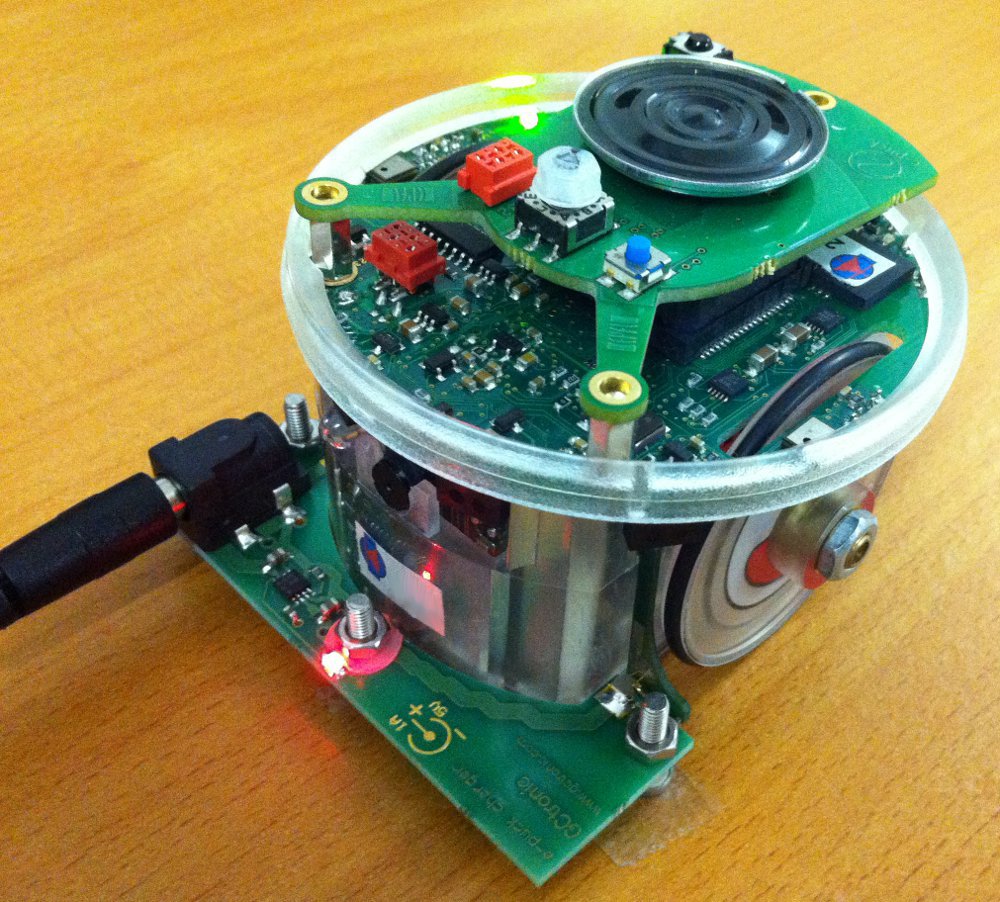
| | Robot equipped with the cliff sensor: <br/> |
| | <span class="plainlinks">[http://www.gctronic.com/doc/images/Cliff+charger.jpg <img width=300 src="http://www.gctronic.com/doc/images/Cliff+charger.jpg">]</span> <br/> |
|
| |
|
| If you want to set the <code>PATH</code> variable permanently, then you need to set it in the <code>.profile</code> file by issuing the command:<br>
| | The robot can be easily moved to the charging station as shown in the following figure: <br/> |
| <code>echo 'export PATH=your_installation_path/Eclipse_e-puck2/Tools/gcc-arm-none-eabi-7-2017-q4-major/bin:$PATH' >> ~/.profile</code><br> | | <span class="plainlinks">[http://www.gctronic.com/doc/images/Cliff-charging.jpg <img width=300 src="http://www.gctronic.com/doc/images/Cliff-charging.jpg">]</span> <br/> |
| Close and reopen the terminal before using your newly set environment variable.
| |
|
| |
|
| Note : The <code>arm-none-eabi</code> version can differ from the one given in this example. It could be needed to adapt the path to the correct version.
| | The following figure shows the two additional sensors (near the wheels) mounted on the cliff module and the three frontal sensors of the ground module: <br/> |
| | <span class="plainlinks">[http://www.gctronic.com/doc/images/Cliff-zoom.jpg <img width=300 src="http://www.gctronic.com/doc/images/Cliff-zoom.jpg">]</span> <br/> |
|
| |
|
| ==Installation for Mac== | | ==Videos== |
| ===Command Line Tools ===
| | {{#ev:youtube|7iFmLBng3qg}} |
| To compile on Mac with <code>Eclipse_e-puck2</code>, it is necessary to have the <code>Command Line Tools</code> installed. It is a bundle of many commonly used tools.<br>
| | {{#ev:youtube|NYOcb1QoUTM}} |
| You can install it by typing the following command in a terminal window: <code>xcode-select --install</code>. It will then open a popup asking you if you want to install this bundle. Otherwise it will tell you it is already installed.
| |
| | |
| ===Java 8===
| |
| This section can be ignored if Java is already installed on your computer.<br>
| |
| To verify whether it is installed or not you can type the following command into a terminal window. It will list all the Java runtimes installed on your Mac: <code>/usr/libexec/java_home -V</code><br>
| |
| You need to have <code>AdoptOpenJDK 8</code> listed to be able to run <code>Eclipse_e-puck2</code>.
| |
| | |
| # Go to [https://adoptopenjdk.net/releases.html OpenJDK download page] and download the <code>OpenJDK 8 (LTS) HotSpot for MacOS x64 JDK</code> (take the installer, aka. <code>.pkg</code> file).
| |
| # Open the <code>.pkg</code> file downloaded and follow the instructions to proceed with the installation of OpenJDK.
| |
| :<span class="plain links">[https://projects.gctronic.com/epuck2/wiki_images/openjdk-mac.png <img width=700 src="https://projects.gctronic.com/epuck2/wiki_images/openjdk-mac.png">]</span><br/>
| |
| :''OpenJDK download page''
| |
| | |
| ===Eclipse_e-puck2===
| |
| :1. Download the [https://projects.gctronic.com/epuck2/Eclipse_e-puck2/Eclipse_e-puck2_Mac_03.21.dmg Eclipse_e-puck2 package for Mac].
| |
| :2. Open the <code>.dmg</code> file downloaded (confirm opening if a warning message appear) and ''drag and drop'' the <code>Eclipse_e-puck2.app</code> into the <code>Applications</code> folder
| |
| ::Note: you can place the <code>Eclipse_e-puck2.app</code> anywhere, as long as the full path to it doesn’t contain any space, if you don’t want it to be in <code>Applications</code>.
| |
| :3. You can create an Alias to <code>Eclipse_e-puck2.app</code> and place it anywhere if you want.
| |
| | |
| ===First launch and Gatekeeper===
| |
| It’s very likely that <code>Gatekeeper</code> (one of the protections of Mac OS) will prevent you to launch <code>Eclipse_e-puck2.app</code> because it isn’t signed from a known developer.<br>
| |
| If you can’t run the program because of a warning of the system, press <code>OK</code> and try to launch it by right clicking on it and choosing <code>open</code> in the contextual menu (may be slow to open the first time).<br>
| |
| If <code>Unable to open "Eclipse_e-puck2.app" because this app comes from an unidentified developer.</code> or if <code>"Eclipse.app" is corrupted and cannot be opened. You should place this item in the Trash.</code> appears after executing the app the first time, it is needed to disable temporarily <code>Gatekeeper</code>.
| |
| | |
| To do so :
| |
| | |
| :1. Go to <code>System Preferences->security and privacy->General</code> and authorize downloaded application from <code>Anywhere</code>.
| |
| | |
| ::<span class="plain links">[https://projects.gctronic.com/epuck2/wiki_images/security_tab_mac.png <img width=500 src="https://projects.gctronic.com/epuck2/wiki_images/security_tab_mac.png">]</span><br/>
| |
| ::''Security settings of Mac OS''
| |
| | |
| ::If you are on Mac OS Sierra or greater (greater or equal to Mac OS 10.12), you must type the following command on the terminal to make the option above appear.
| |
| ::<code>sudo spctl --master-disable</code>
| |
| :2. Now you can try to run the application and it should work.
| |
| :3. If Eclipse opened successfully, it is time to reactivate <code>Gatekeeper</code>. Simply set back the setting of <code>Gatekeeper</code>.
| |
| ::For the ones who needed to type a command to disable <code>Gatekeeper</code>, here is the command to reactivate it.
| |
| ::<code>sudo spctl --master-enable</code>
| |
| | |
| This procedure is only needed the first time. After that <code>Gatekeeper</code> will remember your choice to let run this application and will not bother you anymore, as long as you use this application. If you re-download it, you will have to redo the procedure for <code>Gatekeeper</code>.
| |
| | |
| '''Important things to avoid :'''
| |
| :1. The path to the <code>Eclipse_e-puck2.app</code> must contain zero space.
| |
| ::Example :
| |
| ::<code>/home/student/epfl_stuff/Eclipse_e-puck2</code> OK
| |
| ::<code>/home/student/epfl stuff/Eclipse_e-puck2</code> NOT OK
| |
| :2. The file’s structure in the <code>Eclipse_e-puck2.app</code> must remain the same. It means no file inside this app must be moved to another place.
| |
| | |
| ===Configuring the PATH variable===
| |
| The <code>PATH</code> variable is an environment variable used to store a list of the paths to the folders containing the executables we can then run in a terminal from any path.
| |
| | |
| If you want to use the <code>arm-none-eabi</code> toolchain provided inside the <code>Eclipse_e-puck2</code> package, you have to add it to the <code>PATH</code> variable to be able to call it inside a terminal window. To set the <code>PATH</code> variable you need to issue the following command:
| |
| | |
| <code>export PATH=your_installation_path/Eclipse_e-puck2.app/Contents/Eclipse_e-puck2/Tools/gcc-arm-none-eabi-7-2017-q4-major/bin:$PATH</code>
| |
| | |
| If you put the <code>Eclipse_e-puck2.app</code> into the <code>Applications</code> folder then the exact command would be:
| |
| | |
| <code>export PATH=/Applications/Eclipse_e-puck2.app/Contents/Eclipse_e-puck2/Tools/gcc-arm-none-eabi-7-2017-q4-major/bin:$PATH</code>
| |
| | |
| What is important to know is that this procedure is temporary. It applies only to the terminal window used to type it. If you open a new terminal window or close this one, you will have to set again the <code>PATH</code> variable.
| |
| | |
| If you want to set the <code>PATH</code> variable permanently, then you need to set it in the <code>.bash_profile</code> file by issuing the command:<br>
| |
| <code>echo 'export PATH=your_installation_path/Eclipse_e-puck2.app/Contents/Eclipse_e-puck2/Tools/gcc-arm-none-eabi-7-2017-q4-major/bin:$PATH' >> ~/.bash_profile</code><br>
| |
| Close and reopen the terminal before using your newly set environment variable.
| |
| | |
| Note : The <code>arm-none-eabi</code> version can differ from the one given in this example. It could be needed to adapt the path to the correct version.
| |
| | |
| =Get the source code=
| |
| The code of the e-puck2 is open source and is available as a git repository. To download the source code you need to install git on your system:
| |
| * Windows: downlaod git from [https://gitforwindows.org/ https://gitforwindows.org/] and follow the installation instructions (default configuration is ok)
| |
| * Linux: issue the command <code>sudo apt-get install git</code>
| |
| * Mac: issue the command <code>brew install git</code>
| |
| | |
| The source code can downloaded with the command: <code>git clone --recursive https://github.com/e-puck2/e-puck2_main-processor.git</code><br/>
| |
| The command must be issued in <code>Git bash</code> on Windows, or in a terminal on Linux / Mac.
| |
| | |
| This repository contains the main microcontroller factory firmware together with the e-puck2 library. This library includes all the functions needed to interact with the robot's sensors and actuators; the factory firmware shows how to use these functions.<br/>
| |
| | |
| A snapshot of the repository can be downloaded from [https://projects.gctronic.com/epuck2/e-puck2_main-processor_snapshot_17.03.20_1f56587.zip e-puck2_main-processor_snapshot_17.03.20.zip].<br/>
| |
| | |
| =Creating a project=
| |
| ==Main microcontroller factory firmware project==
| |
| If you want to modify the code of the factory firmware running on the main microcontroller, or if you want to have a look at the implementation details, then you can add this project in Eclipse by following the next steps:<br/>
| |
| :1 Run Eclipse and then select <code>File->New->Makefile Project with Existing Code</code>.
| |
| ::<span class="plain links">[https://projects.gctronic.com/epuck2/wiki_images/e-puck2-dev3-1.png <img width=500 src="https://projects.gctronic.com/epuck2/wiki_images/e-puck2-dev3-1_small.png">]</span><br/>
| |
| :2 Next click on the <code>Browse</code> button and choose the project folder of the git repository downloaded previously (should be named <code>e-puck2_main-processor</code>) and set a project name (otherwise you can keep the one created by Eclipse). Choose <code>None</code> for the the toolchain.
| |
| :3 Click on the <code>Finish</code> button and the project is added to Eclipse.
| |
| ::<span class="plain links">[https://projects.gctronic.com/epuck2/wiki_images/e-puck2-dev3-2.png <img width=500 src="https://projects.gctronic.com/epuck2/wiki_images/e-puck2-dev3-2_small.png">]</span><br/>
| |
| :4 Build the project by selecting one directory of the project from the left panel and then <code>Project->Build Project</code>.
| |
| | |
| ==Project template==
| |
| The main microcontroller factory firmware project can also be used as a library to build your own project on top of it.<br>
| |
| | |
| To accomplish that, you have to copy the folder <code>Project_template</code>, contained in the <code>e-puck2_main-processor</code> project, and place it in the same directory of the <code>e-puck2_main-processor</code> project; you can of course rename the folder to the name you want (e.g. <code>myproject</code>). You must end up with the following directory tree:<br>
| |
| * e-puck2
| |
| ** e-puck2_main-processor
| |
| ** myproject
| |
| | |
| Then you can add this project in Eclipse by following the next steps:
| |
| # Run Eclipse and then select <code>File->New->Makefile Project with Existing Code</code>.
| |
| # Next click on the <code>Browse</code> button and choose the project folder of your project (e.g. <code>myproject</code>) and set a project name (otherwise you can keep the one created by Eclipse). Choose <code>None</code> for the the toolchain.
| |
| # Click on the <code>Finish</code> button and the project is added to Eclipse.
| |
| # Select the project root folder and go to <code>Project->Properties->C/C++ General->Preprocessor Include Paths, Macros etc->Providers</code> and check <code>CDT Cross GCC Built-in Compiler Settings</code>.<br> Then in the textbox below, write <code>arm-none-eabi-gcc ${FLAGS} -E -P -v -dD "${INPUTS}"</code>.
| |
| # Create a linked folder inside your project that links to the <code>e-puck2_main-processor</code> library. This allows Eclipse to index the declarations and implementations of the functions and variables in the code of the library.
| |
| ##Select the project root folder and go to <code>File->New->Folder</code>.
| |
| ##Check <code>Advanced >></code> on the bottom.
| |
| ##Choose <code>Link to alternate location (Linked Folder)</code>.
| |
| ##Type <code>PROJECT_LOC/../e-puck2_main-processor</code> and click the <code>Finish</code> button.
| |
| # Build the project by selecting one file of the project from the left panel and then <code>Project->Build Project</code>. The result of the compilation will appear in the <code>build</code> folder in your project folder.
| |
| # After you compile the project, select the project root folder and go to <code>Project->C/C++ Index->Rebuild</code> to rebuild the index (we need to have compiled at least one time in order to let Eclipse find all the paths to the files used).
| |
| | |
| Now you can write your own program. If you want to add source files (<code>.c</code>) to the project you need to add them also in the <code>makefile</code>, in the <code>CSRC</code> definition. All the headers files (<code>.h</code>) located next to the <code>makefile</code> are automatically included in the compilation, but if you need to place them into folders, you have to specify these folders in the <code>makefile</code>, in the <code>INCDIR</code> definition. The same is needed for any desired <code>.h</code> files from other external folders.<br/>
| |
| In the <code>makefile</code> you can also set the name of your project.<br/>
| |
| This <code>makefile</code> uses the main makefile of the <code>e-puck2_main-processor</code> project. This means you can add custom commands to the <code>makefile</code> but it should not interfere with the main makefile.
| |
| | |
| =Configuring the Debugger's settings=
| |
| <code>Eclipse_e-puck2</code> contains everything needed to compile, program and debug the e-puck2.<br>
| |
| The only settings to configure with a new project are located under the <code>Debug Configurations</code> icon of Eclipse (you can also find it on <code>Run->Debug Configurations</code>).
| |
| :<span class="plain links">[https://projects.gctronic.com/epuck2/wiki_images/Debug_configuration.png <img width=231 src="https://projects.gctronic.com/epuck2/wiki_images/Debug_configuration.png">]</span><br/>
| |
| Once in the settings, select <code>Generic Blackmagic Probe</code> preset on the left panel. Then you need to configure two things :
| |
| | |
| # In the <code>main</code> tab, select which project to debug and the path to the compiled file. If the project has already been compiled, Eclipse should have indexed the binaries and you can list the project and the compiled files using respectively the <code>Browse...</code> and <code>Search Project...</code> buttons.<br/> If nothing is appearing when you press <code>Search Project...</code> then you must enter the <code>.elf</code> file name by hand, which can be found in your project <code>build</code> folder (e.g. <code>build/e-puck2_main-processor.elf</code>).
| |
| # In the <code>Startup</code> tab, you need to replace the serial port name written on the first line of the text box by the one used by the GDB Server of your robot. [http://www.gctronic.com/doc/index.php?title=e-puck2#Finding_the_USB_serial_ports_used See how to find it].
| |
| :* For Windows, it will be <code>\\.\COMX</code>, <code>X</code> being the port number.
| |
| :* For Linux, it will be <code>/dev/ttyACMX</code>, <code>X</code> being the port number
| |
| :* For Mac, it will be <code>/dev/cu.usbmodemXXXXX</code>, <code>XXXXX</code> being the port number.
| |
| :* You can also type <code>${COM_PORT}</code> instead of the com port in order to use the variable <code>COM_PORT</code> for the debug configuration.<br>To change the value of this variable, go to the <code>main</code> tab again, click on the <code>Variables...</code> button and click on the <code>Edit Variables...</code> button. The opened window will let you edit the value of the variable.<br>Using the variable <code>COM_PORT</code> instead of the real com port in a debug configuration is useful if for example you have multiple debug configurations. If for some reason you need to change the serial port to use, then you can simply edit the variable <code>COM_PORT</code> instead of editing the serial port for each debug configuration.
| |
| | |
| If you want to debug another project, you can duplicate this settings and change the relevant parts (project name and path to compiled file) in order to have one launch configuration for each project.<br/>
| |
| :<span class="plain links">[https://projects.gctronic.com/epuck2/wiki_images/e-puck2-debug.jpg <img width=400 src="https://projects.gctronic.com/epuck2/wiki_images/e-puck2-debug-small.jpg">]</span><br/>
| |
| | |
| Now you should be able to use the debugger with Eclipse.
| |
| | |
| Notice that the settings are saved in the project folder in a file with extension <code>.launch</code>. If you want, you can rename this file (e.g. <code>Debug_project_template.launch</code>) with the name you want for the debug configuration of your project.
| |
| | |
| =Running a debugging session=
| |
| Once the debugger is configured, you can start a debugging session. When starting a session, the robot is programmed with the current developed program, thus starting a debugging session means also updating the main microcontroller firmware. This is in fact the way to update the firwmare via Eclipse; to do it manually refer to the section [http://www.gctronic.com/doc/index.php?title=e-puck2#Firmware_update Main microcontroller: firmware update].
| |
| | |
| To start a session follow the next steps:
| |
| # Connect the robot to the computer and turn it on
| |
| # From Eclipse, launch the debug configuration previously set: from the menu <code>Run->Debug configurations...</code>, select the configuration and click on the <code>Debug</code> button.<br>Alternatively you can directly select your configuration from the debugger drop-down menu.<br><span class="plain links">[https://projects.gctronic.com/epuck2/wiki_images/e-puck2-debug2.png <img width=350 src="https://projects.gctronic.com/epuck2/wiki_images/e-puck2-debug2.png">]</span><br/>
| |
| # When the debugging session is started, Eclipse will change the view to the <code>Debug perspective</code>. Right-click on the main process and select <code>Restart</code> to restart the program from the beginning<br><span class="plain links">[https://projects.gctronic.com/epuck2/wiki_images/e-puck2-debug3.png <img width=500 src="https://projects.gctronic.com/epuck2/wiki_images/e-puck2-debug3-small.png">]</span>
| |
| # Click on the <code>Resume</code> button on top of the window to start your program. Now you can suspend and resume whenever you want, then when you want to modify your code again you click on the <code>Terminate</code> button and click on the <code>C/C++ perspective</code> button.<br><span class="plain links">[https://projects.gctronic.com/epuck2/wiki_images/e-puck2-debug4.png <img width=500 src="https://projects.gctronic.com/epuck2/wiki_images/e-puck2-debug4-small.png">]</span>
| |
| | |
| ==Adding breakpoints==
| |
| | |
| ==Watch variables==
| |
| | |
| ==Analyze microcontroller registers content==
| |
| When a debugging session is started, the microcontroller's registers state can be inspected by clicking on the <code>EmbSys Registers</code> tab on the top right side of the <code>Debug perspective</code>.
| |
| <br><span class="plain links">[https://projects.gctronic.com/epuck2/wiki_images/e-puck2-debug5.png <img width=500 src="https://projects.gctronic.com/epuck2/wiki_images/e-puck2-debug5-small.png">]</span>
| |
| | |
| ==Bluetooth debugging session==
| |
| It is possible to run a debugging session remotely thorugh Bluetooth following these steps:
| |
| # change the programmer's mode to <code>mode 1</code> with the command <code>monitor select_mode 1</code>, for more informations refer to [https://www.gctronic.com/doc/index.php?title=e-puck2_programmer_development e-puck2 programmer development], chapter <code>Configuring the Programmer's settings</code>
| |
| # pair the robot with the computer
| |
| # in the debugger's settings, setup the port with the <code>Bluetooth channel 1, GDB port</code> name, for more informations refer to [https://www.gctronic.com/doc/index.php?title=e-puck2_PC_side_development#Connecting_to_the_Bluetooth Connecting to the Bluetooth]
| |
| # start the debugging session and the Bluetooth connection will be established automatically; now you can program/debug the robot remotely
| |
| | |
| Beware that GDB over the Bluetooth connection of the e-puck2 is much slower than with USB and it doesn't work with Windows due to GDB limitations on this OS.
| |
| | |
| =Local communication=
| |
| Local range infrared communication between e-puck2 robots can be achieved using the infrared sensors of the robots to transmit and receive information. The communication system is multiplexed with the proximity sensing system commonly used on the robots, thus it is possible to both communicate and avoid obstacles.<br/>
| |
| | |
| The implementation is based on the [http://www.e-puck.org/index.php?option=com_content&view=article&id=32&Itemid=28 libIrcom] library developed for the e-puck1 robots and it keeps retro-compatibility. This means that an e-puck1 is able to communicate with an e-puck2, so you can still use your e-puck1 robots together with e-puck2 to form a bigger fleet of robots for your experiments. Moreover the API is the same, thus the code developed for the e-puck1 can be used easily also with the e-puck2.<br/>
| |
| | |
| Here are some details about the current implementation of the local communication module:
| |
| * messages are encoded using a frequency modulation that permits usage in a wide range of light conditions
| |
| * the module allows communications at a rate of up to 30 bytes per seconds (maximum theoretical throughput)
| |
| * support half-duplex communication
| |
| * use the infrared sensors to exchange data, thus during reception/transmission the proximity sensors cannot be used to avoid obstacles; the sensors update frequency is at most 5 Hz
| |
| * messages can be detected at a distance of about 7 cm (good reception), and even up to 12-13 cm (sparse reception)
| |
| * messages are stored in a queue (up to 20 messages) and can be retrieved at any time, unless they are overwritten when the queue is full
| |
| | |
| The local communication module is integrated in the factory firmware, so if you want to have a look at the code refer to section [https://www.gctronic.com/doc/index.php?title=e-puck2_robot_side_development#Get_the_source_code Get the source code].<br/>
| |
| A simple exmaple exploiting the local communication can be found in the factory firmware. Put the selector in position 9 and connect the USB cable to the robot: the messages received will be printed in the terminal while the robot continuously send messages to other robots (transceiver behavior). The body led is toggled at each message reception.
| |
| | |
| If an higher throughput and a longer communication distance are required, there is the [http://www.gctronic.com/doc/index.php/Others_Extensions#Range_and_bearing range and bearing extension] designed for this purpose.
| |
| | |
| ==Synchronize example==
| |
| This is a more advanced example exploiting the local communication. Basically the robots programmed with this demo will eventually orient themselves in the same direction, this is accomplished by exchanging data locally between them.
| |
| | |
| The same example is also available for e-puck1 robots (see [http://www.e-puck.org/index.php?option=com_content&view=article&id=32&Itemid=28 libIrcom]), so you can test it with a mix of robots.
| |
| | |
| The pre-built firmware is available here [https://projects.gctronic.com/epuck2/e-puck2_example_synchronize_10.12.19_734d1f7.elf e-puck2_example_synchronize.elf (10.12.19)].
| |
| | |
| ===Usage===
| |
| When the robot is turned on, it starts exchanging information with other robots and try to align with them.<br/>
| |
| Beware that the selector position is taken as the id of the robot, so you need to place the selector in a different position for each robot.<br/>
| |
| Basically you need to put the selector in an unused position, turn on the robot and place it near the others. The robots will eventually align in the same direction.
| |
| | |
| ===Building===
| |
| First of all download the source code with the command: <code>git clone https://github.com/e-puck2/e-puck2_example_synchronize.git</code><br/>
| |
| The command must be issued in <code>Git bash</code> on Windows, or in a terminal on Linux / Mac.<br/>
| |
| Place the cloned repo folder <code>e-puck2_example_synchronize</code> in the same directory of the <code>e-puck2_main-processor</code> project; you must end up with the following directory tree:<br>
| |
| * e-puck2
| |
| ** e-puck2_main-processor
| |
| ** e-puck2_example_synchronize
| |
| | |
| Then you can add this project in Eclipse by following the next steps:
| |
| # Run Eclipse and then select <code>File->New->Makefile Project with Existing Code</code>.
| |
| # Next click on the <code>Browse</code> button and choose the project folder <code>e-puck2_example_synchronize</code>. Choose <code>None</code> for the the toolchain.
| |
| # Click on the <code>Finish</code> button and the project is added to Eclipse.
| |
| # Select the project root folder and go to <code>Project->Properties->C/C++ General->Preprocessor Include Paths, Macros etc->Providers</code> and check <code>CDT Cross GCC Built-in Compiler Settings</code>.<br> Then in the textbox below, write <code>arm-none-eabi-gcc ${FLAGS} -E -P -v -dD "${INPUTS}"</code>.
| |
| # Create a linked folder inside your project that links to the <code>e-puck2_main-processor</code> library. This allows Eclipse to index the declarations and implementations of the functions and variables in the code of the library.
| |
| ##Select the project root folder and go to <code>File->New->Folder</code>.
| |
| ##Check <code>Advanced >></code> on the bottom.
| |
| ##Choose <code>Link to alternate location (Linked Folder)</code>.
| |
| ##Type <code>PROJECT_LOC/../e-puck2_main-processor</code> and click the <code>Finish</code> button.
| |
| # Build the project by selecting one file of the project from the left panel and then <code>Project->Build Project</code>. The result of the compilation will appear in the <code>build</code> folder in your project folder.
| |
| # After you compile the project, select the project root folder and go to <code>Project->C/C++ Index->Rebuild</code> to rebuild the index (we need to have compiled at least one time in order to let Eclipse find all the paths to the files used).
| |
| | |
| ==Master-slave example==
| |
| For this example two robots equipped with the [https://www.gctronic.com/doc/index.php?title=Others_Extensions#Ground_sensors ground sensors extension] are needed: one acts as a master (transmitter) and the other as a slave (receiver). The master send a command (1 byte) to the slave indicating the current color of its RGB LEDs and the slave when receives the command, interpret it and set its RGB LEDs color to the same color of the master. The ground sensors extension is used to move the robots along a black line in order to follow a desired path.
| |
| | |
| The pre-built firmware is available here [https://projects.gctronic.com/epuck2/e-puck2_example_master_slave_03.03.20_00311f3.elf e-puck2_example_master_slave.elf (03.03.20)].
| |
| | |
| ===Usage===
| |
| Program the two robots with this demo and set the selector to position 0 for one robot (master) and position 1 (any position but zero would be ok) for the other (slave).<br/>
| |
| Print this [https://projects.gctronic.com/epuck2/master-slave-path.pdf master-slave-path.pdf] and place the master on one side and the slave in the other side.<br/>
| |
| Both robots will move back and forth and when they encounter each other, the master will send its RGB LEDs state to the slave that will reflect the same state on its own RGB LEDs.<br/>
| |
| You can try different paths and also add more robots with slighly modifications to the code, this is only a starting point.<br/>
| |
| Beware that the robots will detect each other thanks to the proximity sensors values and they start to exchange data only when they're facing each other. This behavior can be changed by continuously exchanging data, in this way you can play also with different distances between the robot's path.
| |
| | |
| ===Building===
| |
| First of all download the source code with the command: <code>git clone https://github.com/e-puck2/e-puck2_example_master_slave.git</code><br/>
| |
| The command must be issued in <code>Git bash</code> on Windows, or in a terminal on Linux / Mac.<br/>
| |
| Place the cloned repo folder <code>e-puck2_example_master_slave</code> in the same directory of the <code>e-puck2_main-processor</code> project; you must end up with the following directory tree:<br>
| |
| * e-puck2
| |
| ** e-puck2_main-processor
| |
| ** e-puck2_example_master_slave
| |
| | |
| Then you can add this project in Eclipse by following the next steps:
| |
| # Run Eclipse and then select <code>File->New->Makefile Project with Existing Code</code>.
| |
| # Next click on the <code>Browse</code> button and choose the project folder <code>e-puck2_example_master_slave</code>. Choose <code>None</code> for the the toolchain.
| |
| # Click on the <code>Finish</code> button and the project is added to Eclipse.
| |
| # Select the project root folder and go to <code>Project->Properties->C/C++ General->Preprocessor Include Paths, Macros etc->Providers</code> and check <code>CDT Cross GCC Built-in Compiler Settings</code>.<br> Then in the textbox below, write <code>arm-none-eabi-gcc ${FLAGS} -E -P -v -dD "${INPUTS}"</code>.
| |
| # Create a linked folder inside your project that links to the <code>e-puck2_main-processor</code> library. This allows Eclipse to index the declarations and implementations of the functions and variables in the code of the library. | |
| ##Select the project root folder and go to <code>File->New->Folder</code>.
| |
| ##Check <code>Advanced >></code> on the bottom.
| |
| ##Choose <code>Link to alternate location (Linked Folder)</code>.
| |
| ##Type <code>PROJECT_LOC/../e-puck2_main-processor</code> and click the <code>Finish</code> button.
| |
| # Build the project by selecting one file of the project from the left panel and then <code>Project->Build Project</code>. The result of the compilation will appear in the <code>build</code> folder in your project folder.
| |
| # After you compile the project, select the project root folder and go to <code>Project->C/C++ Index->Rebuild</code> to rebuild the index (we need to have compiled at least one time in order to let Eclipse find all the paths to the files used).
| |
| | |
| =Example projects=
| |
| ==Digital Signal Processing (DSP) and wav playback==
| |
| In this example the [http://www.keil.com/pack/doc/CMSIS/DSP/html/index.html CMSIS-DSP] library is used to compute the Fast Fourier Transform of the signal coming from the microphones. The processing power of the main microntroller let the signal to be processed continuously. Moreover this example shows how to play wav files stored in the micro sd.<br/>
| |
| | |
| The pre-built firmware is available here [https://projects.gctronic.com/epuck2/e-puck2_example_dsp_05.10.18_3aa8b81.elf e-puck2_example_dsp.elf (05.10.18)].
| |
| | |
| ===Usage===
| |
| There are basically two demos in this example, one run on selector position 0 and the other in selector position 1.<br/>
| |
| | |
| When the selector is in position 0, then the resulting frequency (max amplitude bin) of the computed FFT is mapped to the RGB LEDs: LEDs will be blue when frequency detected is around 250..900 Hz, green when frequency is around 900..1500 Hz and red with 1500..2200 Hz. The brightness of the LEDs is also changed with the frequency.<br/>
| |
| The distance sensor (ToF) is also used to detect people in front of the robot. When someone is detected within 50 cm, then the measured distance is mapped to a frequency emitted through the speaker; the generated tone is between 260 Hz (far) and 2240 Hz (near). You can use your hand to play some melody, the robot in the meantime will detect the frequency and show it through the RGB.<br/>
| |
| | |
| When the selector is in position 1, the robot will play a wav file stored in the micro sd when one of the proximity sensors is "touched" (with your finger you go near the proximity and then you go away, like pressing a button). For each proximity there is a different wav file that will be played: for proximity 0 it will be played <code>0.wav</code>, for proximity 1 it will be played <code>1.wav</code> and so on till proximity 7 with <code>7.wav</code>.<br/>
| |
| | |
| All the wav files you need are stored in the <code>wav</code> directory within the project, put all of them in a micro sd partitioned in FAT32 and you're ready to go. Alternatively you can play your own wav files, beware to name them from <code>0.wav</code> to <code>7.wav</code> and they must be 16 KHz, mono.
| |
| | |
| ===Building===
| |
| First of all download the source code with the command: <code>git clone https://github.com/e-puck2/e-puck2_example_dsp.git</code><br/>
| |
| The command must be issued in <code>Git bash</code> on Windows, or in a terminal on Linux / Mac.<br/>
| |
| Place the cloned repo folder <code>e-puck2_example_dsp</code> in the same directory of the <code>e-puck2_main-processor</code> project; you must end up with the following directory tree:<br>
| |
| * e-puck2
| |
| ** e-puck2_main-processor
| |
| ** e-puck2_example_dsp
| |
| | |
| Then you can add this project in Eclipse by following the next steps:
| |
| # Run Eclipse and then select <code>File->New->Makefile Project with Existing Code</code>.
| |
| # Next click on the <code>Browse</code> button and choose the project folder <code>e-puck2_example_dsp</code>. Choose <code>None</code> for the the toolchain.
| |
| # Click on the <code>Finish</code> button and the project is added to Eclipse.
| |
| # Select the project root folder and go to <code>Project->Properties->C/C++ General->Preprocessor Include Paths, Macros etc->Providers</code> and check <code>CDT Cross GCC Built-in Compiler Settings</code>.<br> Then in the textbox below, write <code>arm-none-eabi-gcc ${FLAGS} -E -P -v -dD "${INPUTS}"</code>.
| |
| # Create a linked folder inside your project that links to the <code>e-puck2_main-processor</code> library. This allows Eclipse to index the declarations and implementations of the functions and variables in the code of the library.
| |
| ##Select the project root folder and go to <code>File->New->Folder</code>.
| |
| ##Check <code>Advanced >></code> on the bottom.
| |
| ##Choose <code>Link to alternate location (Linked Folder)</code>.
| |
| ##Type <code>PROJECT_LOC/../e-puck2_main-processor</code> and click the <code>Finish</code> button.
| |
| # Build the project by selecting one file of the project from the left panel and then <code>Project->Build Project</code>. The result of the compilation will appear in the <code>build</code> folder in your project folder.
| |
| # After you compile the project, select the project root folder and go to <code>Project->C/C++ Index->Rebuild</code> to rebuild the index (we need to have compiled at least one time in order to let Eclipse find all the paths to the files used).
| |
| | |
| ==Microphones recording and pitch scaling==
| |
| This example shows how to record the audio (voice) from the onboard microphones and save it in the micro SD.<br/>
| |
| Moreover it applies a pitch scaling algorithm to the data before playing it from the micro SD.<br/>
| |
| The pitch scale processing is based on the SOLA algorithm and a simple implementation is available from the following link [https://www.surina.net/article/time-and-pitch-scaling.html https://www.surina.net/article/time-and-pitch-scaling.html]. Have a look at this site bacause it has a good explanation of the algorithm.<br/>
| |
| | |
| The pre-built firmware is available here [https://projects.gctronic.com/epuck2/e-puck2_example_pitch_scale_07.11.18_26d16f0.elf e-puck2_example_pitch_scale.elf (07.11.18)].
| |
| | |
| ===Usage===
| |
| The example requires a micro SD (FAT32) inserted in the robot.<br/>
| |
| | |
| When the robot is turned on, it waits for the button press that triggers the recording. The voice is recorded for about 2 seconds and saved into the micro SD as wav
| |
| file. Once the recording is finished, the pitch scale is applied and then the modified voice is played.<br/>
| |
| | |
| You can choose whether to get an higher or lower pitch by changing the <code>TIME_SCALE</code> parameter in <code>sola.c</code>:
| |
| * if you want to get an higher pitch, then change <code>TIME_SCALE</code> to a value > 1.0
| |
| * if you want to get a lower pitch, then change the <code>TIME_SCALE</code> to a value < 1.0
| |
| Of course, if the parameter is changed, you need to rebuild the project and reflash the robot.
| |
| | |
| ===Building===
| |
| First of all download the source code with the command: <code>git clone https://github.com/e-puck2/e-puck2_example_pitch_scale.git</code><br/>
| |
| The command must be issued in <code>Git bash</code> on Windows, or in a terminal on Linux / Mac.<br/>
| |
| Place the cloned repo folder <code>e-puck2_example_pitch_scale</code> in the same directory of the <code>e-puck2_main-processor</code> project; you must end up with the following directory tree:<br>
| |
| * e-puck2
| |
| ** e-puck2_main-processor
| |
| ** e-puck2_example_pitch_scale
| |
| | |
| Then you can add this project in Eclipse by following the next steps:
| |
| # Run Eclipse and then select <code>File->New->Makefile Project with Existing Code</code>.
| |
| # Next click on the <code>Browse</code> button and choose the project folder <code>e-puck2_example_pitch_scale</code>. Choose <code>None</code> for the the toolchain.
| |
| # Click on the <code>Finish</code> button and the project is added to Eclipse.
| |
| # Select the project root folder and go to <code>Project->Properties->C/C++ General->Preprocessor Include Paths, Macros etc->Providers</code> and check <code>CDT Cross GCC Built-in Compiler Settings</code>.<br> Then in the textbox below, write <code>arm-none-eabi-gcc ${FLAGS} -E -P -v -dD "${INPUTS}"</code>.
| |
| # Create a linked folder inside your project that links to the <code>e-puck2_main-processor</code> library. This allows Eclipse to index the declarations and implementations of the functions and variables in the code of the library.
| |
| ##Select the project root folder and go to <code>File->New->Folder</code>.
| |
| ##Check <code>Advanced >></code> on the bottom.
| |
| ##Choose <code>Link to alternate location (Linked Folder)</code>.
| |
| ##Type <code>PROJECT_LOC/../e-puck2_main-processor</code> and click the <code>Finish</code> button.
| |
| # Build the project by selecting one file of the project from the left panel and then <code>Project->Build Project</code>. The result of the compilation will appear in the <code>build</code> folder in your project folder.
| |
| # After you compile the project, select the project root folder and go to <code>Project->C/C++ Index->Rebuild</code> to rebuild the index (we need to have compiled at least one time in order to let Eclipse find all the paths to the files used).
| |
| | |
| ==C++==
| |
| A basic example showing how to integrate C++ code in your project is available in the following repository: [https://github.com/e-puck2/e-puck2_cpp https://github.com/e-puck2/e-puck2_cpp].<br/>
| |
| The example demonstrates simple usage of a class and for range loops.
| |
| | |
| ===Building===
| |
| First of all download the source code with the command: <code>git clone https://github.com/e-puck2/e-puck2_cpp.git</code><br/>
| |
| The command must be issued in <code>Git bash</code> on Windows, or in a terminal on Linux / Mac.<br/>
| |
| Place the cloned repo folder <code>e-puck2_cpp</code> in the same directory of the <code>e-puck2_main-processor</code> project; you must end up with the following directory tree:<br>
| |
| * e-puck2
| |
| ** e-puck2_main-processor
| |
| ** e-puck2_cpp
| |
| | |
| Then you can add this project in Eclipse by following the next steps:
| |
| # Run Eclipse and then select <code>File->New->Makefile Project with Existing Code</code>.
| |
| # Next click on the <code>Browse</code> button and choose the project folder <code>e-puck2_cpp</code>. Choose <code>None</code> for the the toolchain.
| |
| # Click on the <code>Finish</code> button and the project is added to Eclipse.
| |
| # Select the project root folder and go to <code>Project->Properties->C/C++ General->Preprocessor Include Paths, Macros etc->Providers</code> and check <code>CDT Cross GCC Built-in Compiler Settings</code>.<br> Then in the textbox below, write <code>arm-none-eabi-gcc ${FLAGS} -E -P -v -dD "${INPUTS}"</code>.
| |
| # Create a linked folder inside your project that links to the <code>e-puck2_main-processor</code> library. This allows Eclipse to index the declarations and implementations of the functions and variables in the code of the library.
| |
| ##Select the project root folder and go to <code>File->New->Folder</code>.
| |
| ##Check <code>Advanced >></code> on the bottom.
| |
| ##Choose <code>Link to alternate location (Linked Folder)</code>.
| |
| ##Type <code>PROJECT_LOC/../e-puck2_main-processor</code> and click the <code>Finish</code> button.
| |
| # Build the project by selecting one file of the project from the left panel and then <code>Project->Build Project</code>. The result of the compilation will appear in the <code>build</code> folder in your project folder.
| |
| # After you compile the project, select the project root folder and go to <code>Project->C/C++ Index->Rebuild</code> to rebuild the index (we need to have compiled at least one time in order to let Eclipse find all the paths to the files used). | |
| | |
| ==Bluetooth echo==
| |
| The aim of this example is to show how to exchange data between the robot and the computer through a Bluetooth connection. The project implements a simple echo behavior, that is what is received by the robot is sent back to the computer.
| |
| | |
| ===Building===
| |
| First of all download the source code with the command: <code>git clone https://github.com/e-puck2/e-puck2_example_bluetooth_echo.git</code><br/>
| |
| The command must be issued in <code>Git bash</code> on Windows, or in a terminal on Linux / Mac.<br/>
| |
| Place the cloned repo folder <code>e-puck2_example_bluetooth_echo</code> in the same directory of the <code>e-puck2_main-processor</code> project; you must end up with the following directory tree:<br>
| |
| * e-puck2
| |
| ** e-puck2_main-processor
| |
| ** e-puck2_example_bluetooth_echo
| |
| | |
| Then you can add this project in Eclipse by following the next steps:
| |
| # Run Eclipse and then select <code>File->New->Makefile Project with Existing Code</code>.
| |
| # Next click on the <code>Browse</code> button and choose the project folder <code>e-puck2_example_bluetooth_echo</code>. Choose <code>None</code> for the the toolchain.
| |
| # Click on the <code>Finish</code> button and the project is added to Eclipse.
| |
| # Select the project root folder and go to <code>Project->Properties->C/C++ General->Preprocessor Include Paths, Macros etc->Providers</code> and check <code>CDT Cross GCC Built-in Compiler Settings</code>.<br> Then in the textbox below, write <code>arm-none-eabi-gcc ${FLAGS} -E -P -v -dD "${INPUTS}"</code>.
| |
| # Create a linked folder inside your project that links to the <code>e-puck2_main-processor</code> library. This allows Eclipse to index the declarations and implementations of the functions and variables in the code of the library.
| |
| ##Select the project root folder and go to <code>File->New->Folder</code>.
| |
| ##Check <code>Advanced >></code> on the bottom.
| |
| ##Choose <code>Link to alternate location (Linked Folder)</code>.
| |
| ##Type <code>PROJECT_LOC/../e-puck2_main-processor</code> and click the <code>Finish</code> button.
| |
| # Build the project by selecting one file of the project from the left panel and then <code>Project->Build Project</code>. The result of the compilation will appear in the <code>build</code> folder in your project folder.
| |
| # After you compile the project, select the project root folder and go to <code>Project->C/C++ Index->Rebuild</code> to rebuild the index (we need to have compiled at least one time in order to let Eclipse find all the paths to the files used).
| |
| | |
| ==Ball detection==
| |
| Pierre Oppliger and WIlliam Galand, during their semester project at EPFL, were able to let the e-puck2 robot reliably recognize a ball independently of light conditions. This is a step towards an e-puck2 football soccer player. For more information about the project (French) and source code, have a look at the repository [https://github.com/e-puck2/e-puck-2-footy https://github.com/e-puck2/e-puck-2-footy].
| |
| | |
| =Firmware update using factory bootloader=
| |
| ==Factory firmware==
| |
| The pre-built firmware is available here [https://projects.gctronic.com/epuck2/e-puck2_main-processor_11.01.21_cf7e095.bin main microcontroller factory firmware.bin (11.01.21)]; it is also available in dfu format here [https://projects.gctronic.com/epuck2/e-puck2_main-processor_11.01.21_cf7e095.dfu main microcontroller factory firmware.dfu (11.01.21)].
| |
| | |
| ==Firmware update==
| |
| This procedure should be used only if the normal firmware update steps described in the section [http://www.gctronic.com/doc/index.php?title=e-puck2#Firmware_update Main microcontroller: firmware update] don't work. This is a recovery procedure.<br/>
| |
| | |
| The main microcontroller features a factory bootloader that can be entered by acting on some special pins, the bootloader mode is called DFU (device firmware upgrade). You can enter DFU mode by first connecting the USB cable, then pressing the button called <code>407 boot</code> while turning on the robot. The button is located near the left wheel, on the bottom side of the electronic board, see the photo below.
| |
| | |
| ::<span class="plain links">[https://projects.gctronic.com/epuck2/wiki_images/F407-dfu.jpg <img width=200 src="https://projects.gctronic.com/epuck2/wiki_images/F407-dfu-small.jpg">]</span><br/>
| |
| ::''Location of the button to put the main microcontroller into DFU''
| |
| | |
| The main microcontroller will be recognized as <code>STM Device in DFU Mode</code> device.
| |
| | |
| '''Note for Windows users''': the device should be recognized automatically (in all Windows versions), but in case it won't be detected then you need to install a <code>libusbK</code> driver for the DFU device.<br>
| |
| Follow the same procedure as explained in section [http://www.gctronic.com/doc/index.php?title=e-puck2#Installing_the_USB_drivers Installing the USB drivers] using <code>libusbK</code> driver instead of <code>USB Serial (CDC)</code>.<br/>
| |
| If you still have problems, try to install the drivers you can find in <code>C:\Program Files (x86)\STMicroelectronics\Software\DfuSe v3.0.6\Bin\Driver</code>.
| |
| | |
| ===Linux/Mac===
| |
| In order to update the main microcontroller firmware you need an utility called <code>dfu-util</code>, it should be already installed from section [http://www.gctronic.com/doc/index.php?title=e-puck2#Installing_the_dependencies_for_firmwares_updates Installing the dependencies for firmwares updates].<br/>
| |
| To uplaod the firmware, issue the following command: <code>sudo dfu-util -d 0483:df11 -a 0 -s 0x08000000 -D your_firmware.bin</code> (the name of the bin file must be changed accordingly).
| |
| | |
| ===Windows===
| |
| Start the <code>DfuSe</code> application (previously installed from section [http://www.gctronic.com/doc/index.php?title=e-puck2#Installing_the_dependencies_for_firmwares_updates Installing the dependencies for firmwares updates]). The programmer in DFU mode will be automatically detected as shown in figure 1. Then you need to open the compiled firmware by clicking on <code>choose</code> and then locating the file with <code>dfu</code> extension, as shown in figure 2. Now click on the <code>upgrade</code> button, a warning message will be shown, confirm the action by clicking on <code>yes</code> as shown in figure 3. If all is ok you'll be prompted with a message saying that the upgrade was successfull as shown in figure 4.<br/>
| |
| <span class="plainlinks">
| |
| <table>
| |
| <tr>
| |
| <td align="center">[1]</td>
| |
| <td align="center">[2]</td>
| |
| <td align="center">[3]</td>
| |
| <td align="center">[4]</td>
| |
| </tr>
| |
| <tr>
| |
| <td>[https://projects.gctronic.com/epuck2/wiki_images/dfu1.png <img width=250 src="https://projects.gctronic.com/epuck2/wiki_images/dfu1.png">]</td>
| |
| <td>[https://projects.gctronic.com/epuck2/wiki_images/dfu2_f407.png <img width=250 src="https://projects.gctronic.com/epuck2/wiki_images/dfu2_f407.png">]</td>
| |
| <td>[https://projects.gctronic.com/epuck2/wiki_images/dfu3.png <img width=250 src="https://projects.gctronic.com/epuck2/wiki_images/dfu3.png">]</td>
| |
| <td>[https://projects.gctronic.com/epuck2/wiki_images/dfu4.png <img width=250 src="https://projects.gctronic.com/epuck2/wiki_images/dfu4.png">]</td>
| |
| </tr>
| |
| </table>
| |
| </span><br/>
| |