e-puck2 robot side development and e-puck2: Difference between pages
| Line 1: | Line 1: | ||
[ | =Hardware= | ||
= | ==Overview== | ||
<span class="plainlinks">[http://www.gctronic.com/doc/images/e-puck2-overview.png <img width=500 src="http://www.gctronic.com/doc/images/e-puck2-overview_small.png">]</span> | |||
<span class="plainlinks">[https://projects.gctronic.com/epuck2/wiki_images/e-puck2-features.png <img width=600 src="https://projects.gctronic.com/epuck2/wiki_images/e-puck2-features_small.png">]</span><br/> | |||
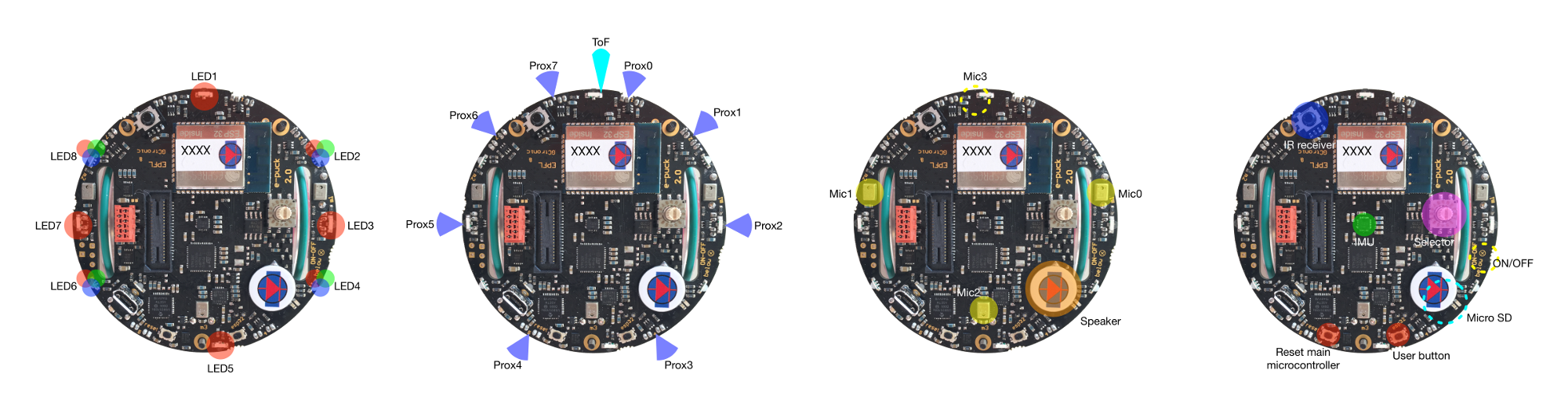
The following figures show the main components offered by the e-puck2 robot and where they are physically placed:<br/> | |||
< | <span class="plainlinks">[https://projects.gctronic.com/epuck2/wiki_images/epuck2-components-position.png <img width=800 src="https://projects.gctronic.com/epuck2/wiki_images/epuck2-components-position_small.png">]</span><br/> | ||
== | ==Specifications== | ||
=== | The e-puck2 robot maintains full compatibility with its predecessor e-puck (e-puck HWRev 1.3 is considered in the following table): | ||
{| border="1" | |||
|'''Feature''' | |||
|'''e-puck1.3''' | |||
|'''e-puck2''' | |||
:< | |'''Compatibility''' | ||
|'''Additional''' | |||
|- | |||
|Size, weight | |||
|70 mm diameter, 55 mm height, 150 g | |||
|Same form factor: 70 mm diameter, 45 mm, 130 g | |||
|style="text-align:center;" | <img width=40 src="http://www.gctronic.com/doc/images/ok.png"> | |||
|No e-jumper required | |||
|- | |||
|Battery, autonomy | |||
|LiIPo rechargeable battery (external charger), 1800 mAh. <br/>About 3 hours autonomy. Recharging time about 2-3h. | |||
|Same battery; USB charging, recharging time about 2.5h. | |||
|style="text-align:center;" | <img width=30 src="http://www.gctronic.com/doc/images/plus.png"> | |||
|USB charging | |||
|- | |||
|Processor | |||
|16-bit dsPIC30F6014A @ 60MHz (15 MIPS), DSP core for signal processing | |||
|32-bit STM32F407 @ 168 MHz (210 DMIPS), DSP and FPU, DMA | |||
|style="text-align:center;" | <img width=30 src="http://www.gctronic.com/doc/images/plus.png"> | |||
|~10 times faster | |||
|- | |||
|Memory | |||
|RAM: 8 KB; Flash: 144 KB | |||
|RAM: 192 KB; Flash: 1024 KB | |||
|style="text-align:center;" | <img width=30 src="http://www.gctronic.com/doc/images/plus.png"> | |||
|RAM: 24x more capable<br/>Flash:~7x more capable | |||
|- | |||
|Motors | |||
|2 stepper motors with a 50:1 reduction gear; 20 steps per revolution; about 0.13 mm resolution | |||
|Same motors | |||
|style="text-align:center;" | <img width=40 src="http://www.gctronic.com/doc/images/ok.png"> | |||
| | |||
|- | |||
|Wheels | |||
|Wheels diamater = 41 mm <br/>Distance between wheels = 53 mm | |||
|Same wheels | |||
|style="text-align:center;" | <img width=40 src="http://www.gctronic.com/doc/images/ok.png"> | |||
| | |||
|- | |||
|Speed | |||
|Max: 1000 steps/s (about 12.9 cm/s) | |||
|Max: 1200 steps/s (about 15.4 cm/s) | |||
|style="text-align:center;" | <img width=30 src="http://www.gctronic.com/doc/images/plus.png"> | |||
|20% faster | |||
|- | |||
|Mechanical structure | |||
|Transparent plastic body supporting PCBs, battery and motors | |||
|Same mechanics | |||
|style="text-align:center;" | <img width=40 src="http://www.gctronic.com/doc/images/ok.png"> | |||
| | |||
|- | |||
|Distance sensor | |||
|8 infra-red sensors measuring ambient light and proximity of objects up to 6 cm | |||
|Same infra-red sensors <br/>Front real distance sensor, Time of fight (ToF), up to 2 meter. | |||
|style="text-align:center;" | <img width=30 src="http://www.gctronic.com/doc/images/plus.png"> | |||
|ToF sensor | |||
|- | |||
|IMU | |||
|3D accelerometer and 3D gyro | |||
|3D accelerometer, 3D gyro, 3D magnetometer | |||
|style="text-align:center;" | <img width=30 src="http://www.gctronic.com/doc/images/plus.png"> | |||
|3D magnetometer | |||
|- | |||
|Camera | |||
|VGA color camera; typical use: 52x39 or 480x1 | |||
|Same camera; typical use: 160x120 | |||
|style="text-align:center;" | <img width=40 src="http://www.gctronic.com/doc/images/ok.png"> | |||
|Bigger images handling | |||
|- | |||
|Audio | |||
|3 omni-directional microphones for sound localization<br/>speaker capable of playing WAV or tone sounds | |||
|4 omni-directional microhpones (digital) for sound localization<br/>speaker capable of playing WAV or tone sounds | |||
|style="text-align:center;" | <img width=30 src="http://www.gctronic.com/doc/images/plus.png"> | |||
| +1 front microphone | |||
|- | |||
|LEDs | |||
|8 red LEDs around the robot, green body light, 1 strong red LED in front | |||
|4 red LEDs and 4 RGB LEDs around the robot, green light, 1 strong red LED in front | |||
|style="text-align:center;" | <img width=30 src="http://www.gctronic.com/doc/images/plus.png"> | |||
|4x RGB LEDs | |||
|- | |||
|Communication | |||
|RS232 and Bluetooth 2.0 for connection and programming | |||
|USB Full-speed, Bluetooth 2.0, BLE, WiFi | |||
|style="text-align:center;" | <img width=30 src="http://www.gctronic.com/doc/images/plus.png"> | |||
|WiFi, BLE | |||
|- | |||
|Storage | |||
|Not available | |||
|Micro SD slot | |||
|style="text-align:center;" | <img width=30 src="http://www.gctronic.com/doc/images/plus.png"> | |||
|Micro SD | |||
|- | |||
|Remote Control | |||
|Infra-red receiver for standard remote control commands | |||
|Same receiver | |||
|style="text-align:center;" | <img width=40 src="http://www.gctronic.com/doc/images/ok.png"> | |||
| | |||
|- | |||
|Switch / selector | |||
|16 position rotating switch | |||
|Same selector | |||
|style="text-align:center;" | <img width=40 src="http://www.gctronic.com/doc/images/ok.png"> | |||
| | |||
|- | |||
|Extensions | |||
|Ground sensors, range and bearing, RGB panel, Gumstix extension, omnivision, your own | |||
|All extension supported | |||
|style="text-align:center;" | <img width=40 src="http://www.gctronic.com/doc/images/ok.png"> | |||
| | |||
|- | |||
|Programming | |||
|Free C compiler and IDE, Webots simulator, external debugger | |||
|Free C compiler and IDE, Webots simulator, onboard debugger (GDB) | |||
|style="text-align:center;" | <img width=30 src="http://www.gctronic.com/doc/images/plus.png"> | |||
|Onboard debugger | |||
|} | |||
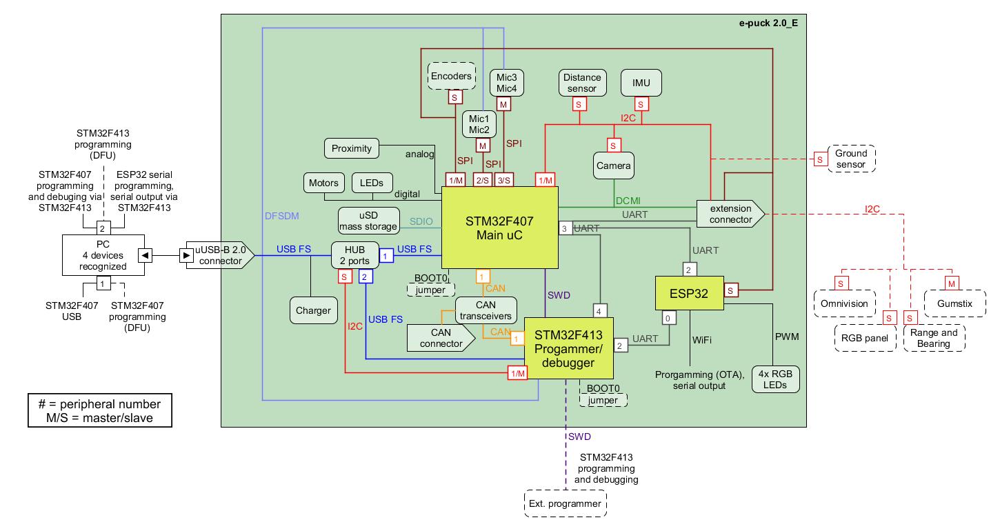
= | This is the overall communication schema:<br/> | ||
<span class="plainlinks">[http://www.gctronic.com/doc/images/comm-overall-e-puck2E.jpg <img width=700 src="http://www.gctronic.com/doc/images/comm-overall-e-puck2E.jpg">]</span><br/> | |||
: | ==Documentation== | ||
:'' | * '''Main microcontroller''': STM32F407, [https://projects.gctronic.com/epuck2/doc/STM32F407xx_datasheet.pdf datasheet], [https://projects.gctronic.com/epuck2/doc/STM32F407_reference-manual.pdf reference-manual] | ||
* '''Programmer/debugger''': STM32F413, [https://projects.gctronic.com/epuck2/doc/STM32F413x_datasheet.pdf datasheet], [https://projects.gctronic.com/epuck2/doc/STM32F413_reference-manual.pdf reference-manual] | |||
* '''Radio module''': Espressif ESP32, [https://projects.gctronic.com/epuck2/doc/esp32_datasheet_en.pdf datasheet], [https://projects.gctronic.com/epuck2/doc/esp32_technical_reference_manual_en.pdf reference-manual] | |||
* '''Camera''': PixelPlus PO8030D CMOS image sensor, [https://projects.gctronic.com/E-Puck/docs/Camera/PO8030D.pdf datasheet], no IR cut filter | |||
: From about July 2019, the camera mounted on the e-puck2 robot is the Omnivision OV7670 CMOS image sensor, [https://projects.gctronic.com/epuck2/doc/OV7670.pdf datasheet] | |||
* '''Microphones''': STM-MP45DT02, [https://projects.gctronic.com/epuck2/doc/mp45dt02.pdf datasheet] | |||
* '''Optical sensors''': Vishay Semiconductors Reflective Optical Sensor, [https://projects.gctronic.com/epuck2/doc/tcrt1000.pdf datasheet] | |||
* '''ToF distance sensor''': STM-VL53L0X, [https://projects.gctronic.com/epuck2/doc/VL53L0X-Datasheet.pdf datasheet], [https://projects.gctronic.com/epuck2/doc/VL53L0X-UserManual-API.pdf user-manual] | |||
* '''IMU''': InvenSense MPU-9250, [https://projects.gctronic.com/epuck2/doc/MPU-9250-product-specification.pdf product-specification], [https://projects.gctronic.com/epuck2/doc/MPU-9250-Register-Map.pdf register-map] | |||
* '''Motors''': [http://www.e-puck.org/index.php?option=com_content&view=article&id=7&Itemid=9 details] | |||
* '''Speaker''': Diameter 13mm, power 500mW, 8 Ohm, DS-1389 or PSR12N08AK or similar | |||
* '''IR receiver''': TSOP36230 | |||
==Migrating from e-puck1.x to e-puck2== | |||
The e-puck2 robot maintains full compatibility with its predecessor e-puck, but there are some improvements that you should be aware of.<br/> | |||
First of all the e-jumper, that is the small board that is attached on top of the e-puck1.x, isn't anymore needed in the e-puck2. The components available on the e-jumper are integrated directly in the robot board. On top of the e-puck2 you'll see a quite big free connector, this is used to attach the extensions board designed for the e-puck1.x that are fully compatible with the e-puck2; you must not connect the e-jumper in this connector.<br/> | |||
The < | |||
Secondly you don't need anymore to unplug and plugin the battery for charging, but instead you can charge the battery (up to 1 ampere) directly by connecting the USB cable. If you want you can still charge the battery with the e-puck1.x external charger, in case you have more than one battery.<br/> | |||
Moreover you don't need anymore a special serial cable (with probably an RS232 to USB adapter) to be able to communicate with the robot, but you can use the USB cable. Once connected to the computer a serial port will be available that you can use to easily exchange data with the robot. | |||
==Extensions== | |||
All the extensions (ground sensors, range and bearing, RGB panel, gumstix and omnvision) are supported by the e-puck2 robot, this means that if you have some extensions for the e-puck1.x you can still use them also with e-puck2.<br/> | |||
For more information about using the gumstix extension with e-puck2 robot refer to [http://www.gctronic.com/doc/index.php?title=Overo_Extension#e-puck2 http://www.gctronic.com/doc/index.php?title=Overo_Extension#e-puck2]. | |||
=Getting Started= | |||
The e-puck2 robot features 3 chips onboard: | |||
* the main microcontroller, that is responsible for handling the sensors and actuators and which runs also the demos/algorithms | |||
* the programmer, that provides programming/debugging capabilties and moreover it configures the USB hub and is responsible for the power management (on/off of the robot and battery measure) | |||
* radio module, that is responsible for handling the wireless communication (WiFi, BLE, BT), the RGB LEDs and the user button (the RGB LEDs and button are connected to the radio module due to the pin number limitation on the main microcontroller) | |||
The robot is shipped with the last firmware version programmed on all 3 chips, so you can immediately start using the robot.<br/> | |||
The following sections explain the basic usage of the robot, <b>all the users should read this chapter completely in order to have a minimal working system ready to play with the e-puck2 robot</b>. Some sections will have more detailed information that can be read by following the links provided. | |||
When required, dedicated informations are given for all platforms (Windows, Linux, Mac). The commands given for Linux are related to the Ubuntu distribution, similar commands are available in other distributions. | |||
== | ==Turn on/off the robot== | ||
To turn on the robot you need to press the power button (blue button) placed on the bottom side of the board, near the speaker, as shown in the following figures: | |||
::<span class="plain links">[https://projects.gctronic.com/epuck2/wiki_images/e-puck2-btn-on-off2.jpg <img width=250 src="https://projects.gctronic.com/epuck2/wiki_images/e-puck2-btn-on-off2-small.jpg">][https://projects.gctronic.com/epuck2/wiki_images/e-puck2-btn-on-off.jpg <img width=300 src="https://projects.gctronic.com/epuck2/wiki_images/e-puck2-btn-on-off-small.jpg">]</span><br/> | |||
To turn off the robot you need to press the power button for 1 second. | |||
==Meaning of the LEDs== | |||
The e-puck2 has three groups of LEDs that are not controllable by the user. | |||
::<span class="plain links">[https://projects.gctronic.com/epuck2/wiki_images/e-puck2_top_leds.png <img width=250 src="https://projects.gctronic.com/epuck2/wiki_images/e-puck2_top_leds.png">]</span><br/> | |||
::''Top view of the e-puck2'' | |||
: | *Charger: RED if charging, GREEN if charge complete and RED and GREEN if an error occurs | ||
*USB: Turned ON if the e-puck2 detects a USB connection with a computer | |||
*STATUS: Turned ON if the robot is ON and OFF if the robot is OFF. When ON, gives an indication of the level of the battery. Also blinks GREEN if the program is running during a debug session. | |||
Battery level indications (STATUS RGB LED): | |||
*GREEN if the system's tension is greater than 3.5V | |||
*ORANGE if the system's tension is between 3.5V and 3.4V | |||
*RED if the system's tension is between 3.4V and 3.3V | |||
*RED blinking if the system's tension is below 3.3V | |||
The robot is automatically turned OFF if the system's tension gets below 3.2V during 10 seconds. | |||
== | ==Connecting the USB cable== | ||
A micro USB cable (included with the robot in the package) is needed to connect the robot to the computer. There are two connectors, one placed on top of the robot facing upwards and the other placed on the side of the robot, as shown in the following figures. Both can be used to charge the robot (up to 1 ampere) or to communicate with it, but do not connect two cables at the same time. Connect the USB cable where is more comfortable to you. | |||
::<span class="plain links">[https://projects.gctronic.com/epuck2/wiki_images/e-puck2-usb-conn.jpg <img width=250 src="https://projects.gctronic.com/epuck2/wiki_images/e-puck2-usb-conn-small.jpg">][https://projects.gctronic.com/epuck2/wiki_images/e-puck2-usb-conn2.jpg <img width=300 src="https://projects.gctronic.com/epuck2/wiki_images/e-puck2-usb-conn2-small.jpg">]</span><br/> | |||
==Installing the USB drivers== | |||
The USB drivers must be installed only for the users of a Windows version older than Windows 10: | |||
#Download and open [https://projects.gctronic.com/epuck2/zadig-2.3.exe zadig-2.3.exe] | |||
#Connect the e-puck2 with the USB cable and turn it on. Three unknown devices appear in the device list of the program, namely '''e-puck2 STM32F407''', '''e-puck2 GDB Server (Interface 0)''' and '''e-puck2 Serial Monitor (Interface 2)'''. | |||
#For each of the three devices mentioned above, select the <code>USB Serial (CDC)</code> driver and click on the <code>Install Driver</code> button to install it. Accept the different prompts which may appear during the process. At the end you can simply quit the program and the drivers are installed. These steps are illustrated on Figure 3 below. | |||
::Note : The drivers installed are located in <code>C:\Users\"your_user_name"\usb_driver</code> | |||
:<span class="plain links">[https://projects.gctronic.com/epuck2/wiki_images/Zadig_e-puck2_STM32F407.png <img width=500 src="https://projects.gctronic.com/epuck2/wiki_images/Zadig_e-puck2_STM32F407.png">]</span><br/> | |||
::''Example of driver installation for e-puck2 STM32F407'' | |||
The drivers are automatically installed with Windows 10, Linux and Mac OS. | |||
Anyway in Linux in order to access the serial ports, a little configuration is needed. Type the following command in a terminal session: <code>sudo adduser $USER dialout</code>. Once done, you need to log off to let the change take effect. | |||
== | ==Finding the USB serial ports used== | ||
Two ports are created by the e-puck2's programmer when the USB cable is connected to the robot (even if the robot is turned off): | |||
* '''e-puck2 GDB Server'''. The port used to program and debug the e-puck2. | |||
* '''e-puck2 Serial Monitor'''. Serial communication between the PC and the radio module (used also to program the radio module). | |||
=== | A third port could be available depending on the code inside the e-puck2's microcontroller. With the factory firmware a port named '''e-puck2 STM32F407''' is created. | ||
===Windows=== | |||
#Open the Device Manager | |||
#Under '''Ports (COM & LPT)''' you can see the virtual ports connected to your computer. | |||
#Do a '''Right-click -> properties''' on the COM port you want to identify. | |||
#Go under the '''details''' tab and select '''Bus reported device description''' in the properties list. | |||
#The name of the port should be written in the text box below. | |||
#Once you found the desired device, you can simply look at its port number '''(COMX)'''. | |||
===Linux=== | |||
:1. Open a terminal window (<code>ctrl+alt+t</code>) and enter the following command: <code>ls /dev/ttyACM*</code> | |||
: | :2. Look for '''ttyACM0''' and '''ttyACM1''' in the generated list, which are respectively '''e-puck2 GDB Server''' and '''e-puck2 Serial Monitor'''. '''ttyACM2''' will be also available with the factory firmware, that is related to '''e-puck2 STM32F407''' port | ||
Note : Virtual serial port numbering on Linux depends on the connections order, thus it can be different if another device using virtual serial ports is already connected to your computer before connecting the robot, but the sequence remains the same. | |||
=== | ===Mac=== | ||
:1. | :1. Open a terminal window and enter the following command: <code>ls /dev/cu.usbmodem*</code> | ||
:2. | :2. Look for two '''cu.usbmodemXXXX''', where XXXX is the number attributed by your computer. You should find two names, with a numbering near to each other, which are respectively '''e-puck2 GDB Server''' (lower number) and '''e-puck2 Serial Monitor''' (higher number). A third device '''cu.usbmodemXXXX''' will be available with the factory firmware, that is related to '''e-puck2 STM32F407''' port | ||
Note : Virtual serial port numbering on Mac depends on the physical USB port used and the device. If you want to keep the same names, you must connect to the same USB port each time. | |||
If you | |||
==PC interface== | |||
<span class="plainlinks">[https://projects.gctronic.com/epuck2/wiki_images/monitor.png <img width=250 src="https://projects.gctronic.com/epuck2/wiki_images/monitor_small.png">]<br/> | |||
A PC application was developed to start playing with the robot attached to the computer via USB cable: you can have information about all the sensors, receive camera images and control the leds and motors.<br/> | |||
Beware that it's not mandatory to download this application in order to work with the robot, but it is a nice demo that gives you an overview of all the sensors and actuators available on the robot, this is a first step to gain confidence with the robot.<br/> | |||
With the factory firmwares programmed in the robot, place the selector in position 8, attach the USB cable and turn on the robot. Enter the correct port (the one related to <code>e-puck2 STM32F407</code>) in the interface and click <code>connect</code>. | |||
The source code is available from the repository [https://github.com/e-puck2/monitor https://github.com/e-puck2/monitor].<br/> | |||
:: | ===Available executables=== | ||
: | * [https://projects.gctronic.com/epuck2/monitor_win.zip Windows executable]: tested on Windows 7 and Windows 10 | ||
* [https://projects.gctronic.com/epuck2/monitor_mac.zip Max OS X executable] | |||
* [https://projects.gctronic.com/epuck2/monitor_linux64bit.tar.gz Ubuntu 14.04 (or later) - 64 bit] | |||
On Linux remember to apply the configuration explained in the chapter [http://www.gctronic.com/doc/index.php?title=e-puck2#Installing_the_USB_drivers Installing the USB drivers] in order to access the serial port. | |||
==Installing the dependencies for firmwares updates== | |||
You can update the firmware for all 3 chips: the main microcontroller, the radio module and the programmer. For doing that, you need some tools to be installed on the system. | |||
===Windows=== | |||
To upload a new firmware in the microcontroller or in the radio module, you don't need to install anything, the packages provided include all the dependencies. | |||
To upload a new firmware in the programmer you need to install an application called <code>DfuSe</code> released by STMicroelectronics. You can download it from [https://projects.gctronic.com/epuck2/en.stsw-stm32080_DfuSe_Demo_V3.0.5.zip DfuSe_V3.0.5.zip]. | |||
===Linux=== | |||
To upload a new firmware in the microcontroller or in the radio module, you need: | |||
* Python (>= 3.4): <code>sudo apt-get install python3</code> | |||
* Python pip: <code>sudo apt-get install -y python3-pip</code> | |||
* pySerial (>= 2.5): <code>sudo pip3 install pyserial</code> | |||
<code> | To upload a new firmware in the programmer you need: | ||
* dfu-util: <code>sudo apt-get install dfu-util</code> | |||
===Mac=== | |||
Install the [https://brew.sh Homewbrew] package manager by opening a terminal and issueing:<br/> | |||
<code>/usr/bin/ruby -e "$(curl -fsSL https://raw.githubusercontent.com/Homebrew/install/master/install)"</code><br/> | |||
and then:<br/> | |||
<code>brew upgrade</code><br/> | |||
<code> | To upload a new firmware in the microcontroller or in the radio module, you need: | ||
* Python (>= 3.4): <code>brew install python</code> (it will install also <code>pip</code>) | |||
* pySerial (>= 2.5): <code>pip3 install pyserial</code> | |||
To upload a new firmware in the programmer you need: | |||
* dfu-util: <code>brew install dfu-util</code> | |||
==PC side development== | |||
This section is dedicated to the users that develop algorithms on the PC side and interact with the robot remotely through a predefined communication protocol. These users don't modify the firmware of the robot, but instead they use the factory firmware released with the robot. They update the robot firmware only when there is an official update. <br/> | |||
The remote control of the robot, by receiving sensors values and setting the actuators, is done through the following channels: Bluetooth, Bluetooth Low Energy, WiFi, USB cable.<br/> | |||
Examples of tools/environment used by these users: | |||
# Aseba | |||
# Simulator (e.g. Webots) | |||
# ROS | |||
# iOS, Android apps | |||
# Custom PC application | |||
# IoT (e.g. IFTTT) | |||
If you fall into this category, then follow this section for more information: [http://www.gctronic.com/doc/index.php?title=e-puck2_PC_side_development PC side development].<br/> | |||
=Main microcontroller= | |||
The e-puck2 robot main microcontroller is a 32-bit STM32F407 that runs at 168 MHz (210 DMIPS) and include DSP, FPU and DMA capabilities. The version chosen for the e-puck2 has 192 KB of total RAM and 1024 KB of flash, so there is a lot of memory to work with.<br/> | |||
This chip is responsible for handling the sensors and actuators and runs also the demos and algorithms. | |||
= | ==Factory firmware== | ||
The | The main microcontroller of the robot is initially programmed with a firmware that includes many demos that could be started based on the selector position, here is a list of the demos with related position and a small description: | ||
* | * Selector position 0: Aseba | ||
* | * Selector position 1: Shell | ||
* | * Selector position 2: Read proximity sensors and when an object is near a proximity, turn on the corresponding LED | ||
* Selector position 3: Asercom protocol v2 (BT) | |||
* Selector positoin 4: Range and bearing extension (receiver) | |||
* Selector position 5: Range and bearing extension - clustering demo (simultaneous transmitter and receiver). | |||
* Selector position 6: Move the robot back and forth exploiting the gyro, with LEDs animation | |||
* Selector position 7: Play a wav (mono, 16 KHz) named "example.wav" from the micro sd when pressing the button | |||
* Selector position 8: Asercom protocol v2 (USB) | |||
* Selector position 9: Local communication: transceiver | |||
* Selector position 10: this position is used to work with the Linux extensions. To work with gumstix refer to [http://www.gctronic.com/doc/index.php?title=Overo_Extension#e-puck2 Overo Extension: e-puck2] , to work with Pi-puck refer to [http://www.gctronic.com/doc/index.php?title=Pi-puck#Requirements Pi-puck: Requirements ]. | |||
* Selector position 11: Simple obstacle avoidance + some animation | |||
* Selector position 12: Hardware test | |||
* Selector position 13: LEDs reflect orientation of the robot | |||
* Selector position 14: Compass | |||
* Selector position 15: WiFi mode | |||
The pre-built firmware is available here [https://projects.gctronic.com/epuck2/e-puck2_main-processor_10.12.21_52ffc6b.elf main microcontroller factory firmware (10.12.21)]. | |||
The | ==Firmware update== | ||
Now and then there could be an official firmware update for the robot and it's important to keep the robot updated with the last firmware to get possibile new features, improvements and for bug fixes.<br/> | |||
The onboard programmer run a GDB server, so we use GDB commands to upload a new firmware, for this reason a toolchain is needed to upload a new firmware to the robot.<br/> | |||
The following steps explain how to update the main microcontroller firmware:<br/> | |||
1. Download the package containing the required toolchain and script to program the robot: [https://projects.gctronic.com/epuck2/e-puck2-prog-main-micro-windows.zip Windows], Linux [https://projects.gctronic.com/epuck2/e-puck2-prog-main-linux32.tar.gz 32 bits]/[https://projects.gctronic.com/epuck2/e-puck2-prog-main-linux64.tar.gz 64 bits], [https://projects.gctronic.com/epuck2/e-puck2-prog-main-micro-macos.zip Mac OS]<br/> | |||
2. Download the last version of the [https://projects.gctronic.com/epuck2/e-puck2_main-processor_10.12.21_52ffc6b.elf main microcontroller factory firmware (10.12.21)], or use your custom firmware<br/> | |||
3. Extract the package and put the firmware file (with <code>elf</code> extension) inside the package directory; beware that only one <code>elf</code> file must be present inside this directory<br/> | |||
4. Attach the USB cable and turn on the robot<br/> | |||
5. Run the script from the package directory:<br/> | |||
:Windows: double click <code>program.bat</code><br/> | |||
:Linux/Mac: issue the following command in a terminal <code>./program.sh</code>. If you get permission errors, then issue <code>sudo chmod +x program.sh</code> to let the script be executable.<br/> | |||
When the upload is complete you'll see an output like in the following figure:<br/> | |||
<span class="plain links">[https://projects.gctronic.com/epuck2/wiki_images/f407-flashing.png <img width=400 src="https://projects.gctronic.com/epuck2/wiki_images/f407-flashing.png">]</span><br/> | |||
The final lines should contain the entry <code>".data",</code>, this means that the upload was successfull. You can then close the terminal window if it is still open. | |||
If you encounter some problem, try to unplug and plug again the USB cable and power cycle the robot, then retry. | |||
= | ==Robot side development== | ||
If you are an embedded developer and are brave enough, then you have complete access to the source code running on the robot, so you can discover what happen inside the main microcontroller and modify it to accomodate your needs. Normally the users that fall into this category develop algorithms optimized to run directly on the microcontroller, such as: | |||
If you | # onboard image processing | ||
# swarm algorithms | |||
# fully autonomous behaviors | |||
# ... | |||
For more information about programming the robot itself, refer to section [http://www.gctronic.com/doc/index.php?title=e-puck2_robot_side_development Robot side development] | |||
= | =Radio module= | ||
The | The radio module chosen for the e-puck is the new ESP32 chip from [https://www.espressif.com/ Espressif], integrating a dual core that run up to 240 MHz, 4 MB of flash and 520 KB of RAM. It supports WiFi standards 802.11 b/g/n (access point mode supported), Bluetooth and Bluetooth LE 4.2. It is the successor of the ESP8266 chip. The following figure shows the various peripherals available on the ESP32:<br/> | ||
<span class="plain links"><img width=400 src="https://projects.gctronic.com/epuck2/wiki_images/esp32-peripherals.png"></span> | |||
This chip first of all is responsible for handling the wireless communication, moreover it handles also the RGB LEDs (with PWM) and the user button. The RGB LEDs and button are connected to the radio module due to the pin number limitation on the main microcontroller. | |||
==Factory firmware== | |||
The radio module of the robot is initially programmed with a firmware that supports Bluetooth communication.<br/> | |||
The pre-built firmware is available here [https://projects.gctronic.com/epuck2/esp32-firmware_11.12.18.zip radio module factory firmware (11.12.18)]. | |||
==WiFi firmware== | |||
At the moment the factory firmware supports only Bluetooth, if you want to work with WiFi you need to program the radio with a dedicated firmware, refer to section [http://www.gctronic.com/doc/index.php?title=e-puck2_PC_side_development#WiFi PC side development: WiFi]. | |||
= | ==BLE firmware== | ||
At the moment the factory firmware supports only calssic Bluetooth, if you want to work with Bluetooth Low Energy you need to program the radio with a dedicated firmware, refer to section [http://www.gctronic.com/doc/index.php?title=e-puck2_mobile_phone_development Mobile phone development]. | |||
==Firmware update== | |||
In order to update the firmware of the ESP32 WiFi module you need to use a python script called <code>esptool</code> provided by [https://www.espressif.com/ Espressif] (manufacturer of the chip). This script was modified to work with the e-puck2 robot and is included in the provided package. The following steps explain how to update the radio module firmware:<br/> | |||
1. Download the package containing the required tools and script to program the robot: [https://projects.gctronic.com/epuck2/e-puck2-prog-radio-windows.zip Windows], [https://projects.gctronic.com/epuck2/e-puck2-prog-radio-macos.zip Linux / Mac]<br/> | |||
2. Download the last version of the [https://projects.gctronic.com/epuck2/esp32-firmware_11.12.18.zip radio module factory firmware (11.12.18)], or use another firmware (e.g. WiFi, BLE, your own). The firmware is composed by 3 files named <code>bootloader.bin</code>, <code>ESP32_E-Puck_2.bin</code> and <code>partitions_singleapp.bin</code><br/> | |||
3. Extract the package and put the firmware files inside the package directory; beware that the name of the <code>.bin</code> files must be the same as indicated in step 2<br/> | |||
4. Attach the USB cable and turn on the robot<br/> | |||
5. Run the script from the package directory:<br/> | |||
:Windows: double click <code>program.bat</code><br/> | |||
:Linux/Mac: issue the following command in a terminal <code>./program.sh</code>. If you get permission errors, then issue <code>sudo chmod +x program.sh</code> to let the script be executable.<br/> | |||
=== | The upload should last about 10-15 seconds and you'll see the progress as shown in the following figure:<br/> | ||
<span class="plain links">[https://projects.gctronic.com/epuck2/wiki_images/esp32-flashing1.png <img width=400 src="https://projects.gctronic.com/epuck2/wiki_images/esp32-flashing1.png">]</span><br/> | |||
When the upload is complete you'll see that all 3 bin files are uploaded correctly as shown in the following figure:<br/> | |||
<span class="plain links">[https://projects.gctronic.com/epuck2/wiki_images/esp32-flashing2.png <img width=400 src="https://projects.gctronic.com/epuck2/wiki_images/esp32-flashing2.png">]</span><br/> | |||
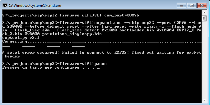
Sometime you could encounter a timeout error as shown in the following figures; in these cases you need to unplug and plug again the USB cable and power cycle the robot, then you can retry.<br/> | |||
<span class="plain links">[https://projects.gctronic.com/epuck2/wiki_images/esp32-flashing3.png <img width=400 src="https://projects.gctronic.com/epuck2/wiki_images/esp32-flashing3.png">]</span> | |||
<span class="plain links">[https://projects.gctronic.com/epuck2/wiki_images/esp32-flashing4.png <img width=400 src="https://projects.gctronic.com/epuck2/wiki_images/esp32-flashing4.png">]</span><br/> | |||
==Development== | |||
Probably, you'll never need to touch the firmware running in the radio module, but in case you need to modify the code or you're simply curious about what is happening at the low level, then refer to the section [http://www.gctronic.com/doc/index.php?title=e-puck2_radio_module_development Radio module development]. | |||
= | =Programmer= | ||
The e-puck2 robot is equipped with an onboard programmer and debugger that let you update the firmware of the robot and debug your code easily using a standard USB interface. There is a dedicated STM32F413 microcontroller that acts as the programmer with built in GDB server, so you can control exactly what happens using the [https://www.gnu.org/software/gdb/ GNU Project Debugger] in your host machine.<br/> | |||
The programmer microcontroller is also in charge of handling various low level features such as the configuration of the USB hub and the power button. | |||
==Factory firmware== | ==Factory firmware== | ||
The pre-built firmware is available here [https://projects.gctronic.com/epuck2/e- | The programmer is initially programmed with a firmware based on a '''''modified version''''' of [https://github.com/blacksphere/blackmagic/wiki Black Magic Probe programmer/debugger].<br/> | ||
The pre-built firmware is available here [https://projects.gctronic.com/epuck2/e-puck2_programmer_28.05.20_3b600ec.bin programmer-firmware.bin (28.05.20)]; it is also available in dfu format here [https://projects.gctronic.com/epuck2/e-puck2_programmer_28.05.20_3b600ec.dfu programmer-firmware.dfu (28.05.20)]. | |||
==Firmware update== | ==Firmware update== | ||
The programmer's microcontroller features a factory bootloader that can be entered by acting on some special pins, the bootloader mode is called DFU (device firmware upgrade). You can enter DFU mode by contacting two pinholes together while inserting the USB cable (no need to turn on the robot). The two pin holes are located near the USB connector of the e-puck2, see the photo below. | |||
::<span class="plain links">[https://projects.gctronic.com/epuck2/wiki_images/e-puck2_top_leds_DFU_413.png <img width=200 src="https://projects.gctronic.com/epuck2/wiki_images/e-puck2_top_leds_DFU_413.png">]</span><br/> | |||
::''Location of the pin holes to put the programmer into DFU'' | |||
The programmer will be recognized as <code>STM Device in DFU Mode</code> device. | |||
The | |||
'''Note for Windows users''': the device should be recognized automatically (in all Windows versions), but in case it won't be detected then you need to install a <code>libusbK</code> driver for the DFU device.<br> | '''Note for Windows users''': the device should be recognized automatically (in all Windows versions), but in case it won't be detected then you need to install a <code>libusbK</code> driver for the DFU device.<br> | ||
Follow the same procedure as explained in section [http://www.gctronic.com/doc/index.php?title=e-puck2#Installing_the_USB_drivers Installing the USB drivers] using <code>libusbK</code> driver instead of <code>USB Serial (CDC) | Follow the same procedure as explained in section [http://www.gctronic.com/doc/index.php?title=e-puck2#Installing_the_USB_drivers Installing the USB drivers] using <code>libusbK</code> driver instead of <code>USB Serial (CDC)</code>. | ||
===Linux/Mac=== | ===Linux/Mac=== | ||
In order to update the | In order to update the programmer firmware you need an utility called <code>dfu-util</code>, it should be already installed from section [http://www.gctronic.com/doc/index.php?title=e-puck2#Installing_the_dependencies_for_firmwares_updates Installing the dependencies for firmwares updates].<br/> | ||
To uplaod the firmware, issue the following command: <code>sudo dfu-util -d 0483:df11 -a 0 -s 0x08000000 -D | To uplaod the firmware, issue the following command: <code>sudo dfu-util -d 0483:df11 -a 0 -s 0x08000000 -D programmer-firmware.bin</code> | ||
===Windows=== | ===Windows=== | ||
| Line 501: | Line 419: | ||
<tr> | <tr> | ||
<td>[https://projects.gctronic.com/epuck2/wiki_images/dfu1.png <img width=250 src="https://projects.gctronic.com/epuck2/wiki_images/dfu1.png">]</td> | <td>[https://projects.gctronic.com/epuck2/wiki_images/dfu1.png <img width=250 src="https://projects.gctronic.com/epuck2/wiki_images/dfu1.png">]</td> | ||
<td>[https://projects.gctronic.com/epuck2/wiki_images/ | <td>[https://projects.gctronic.com/epuck2/wiki_images/dfu2.png <img width=250 src="https://projects.gctronic.com/epuck2/wiki_images/dfu2.png">]</td> | ||
<td>[https://projects.gctronic.com/epuck2/wiki_images/dfu3.png <img width=250 src="https://projects.gctronic.com/epuck2/wiki_images/dfu3.png">]</td> | <td>[https://projects.gctronic.com/epuck2/wiki_images/dfu3.png <img width=250 src="https://projects.gctronic.com/epuck2/wiki_images/dfu3.png">]</td> | ||
<td>[https://projects.gctronic.com/epuck2/wiki_images/dfu4.png <img width=250 src="https://projects.gctronic.com/epuck2/wiki_images/dfu4.png">]</td> | <td>[https://projects.gctronic.com/epuck2/wiki_images/dfu4.png <img width=250 src="https://projects.gctronic.com/epuck2/wiki_images/dfu4.png">]</td> | ||
| Line 507: | Line 425: | ||
</table> | </table> | ||
</span><br/> | </span><br/> | ||
==Development== | |||
The programmer code shouldn't be modified, but if you know what you're doing then refer to section [http://www.gctronic.com/doc/index.php?title=e-puck2_programmer_development Programmer development]. | |||
Revision as of 12:55, 14 December 2021
Hardware
Overview
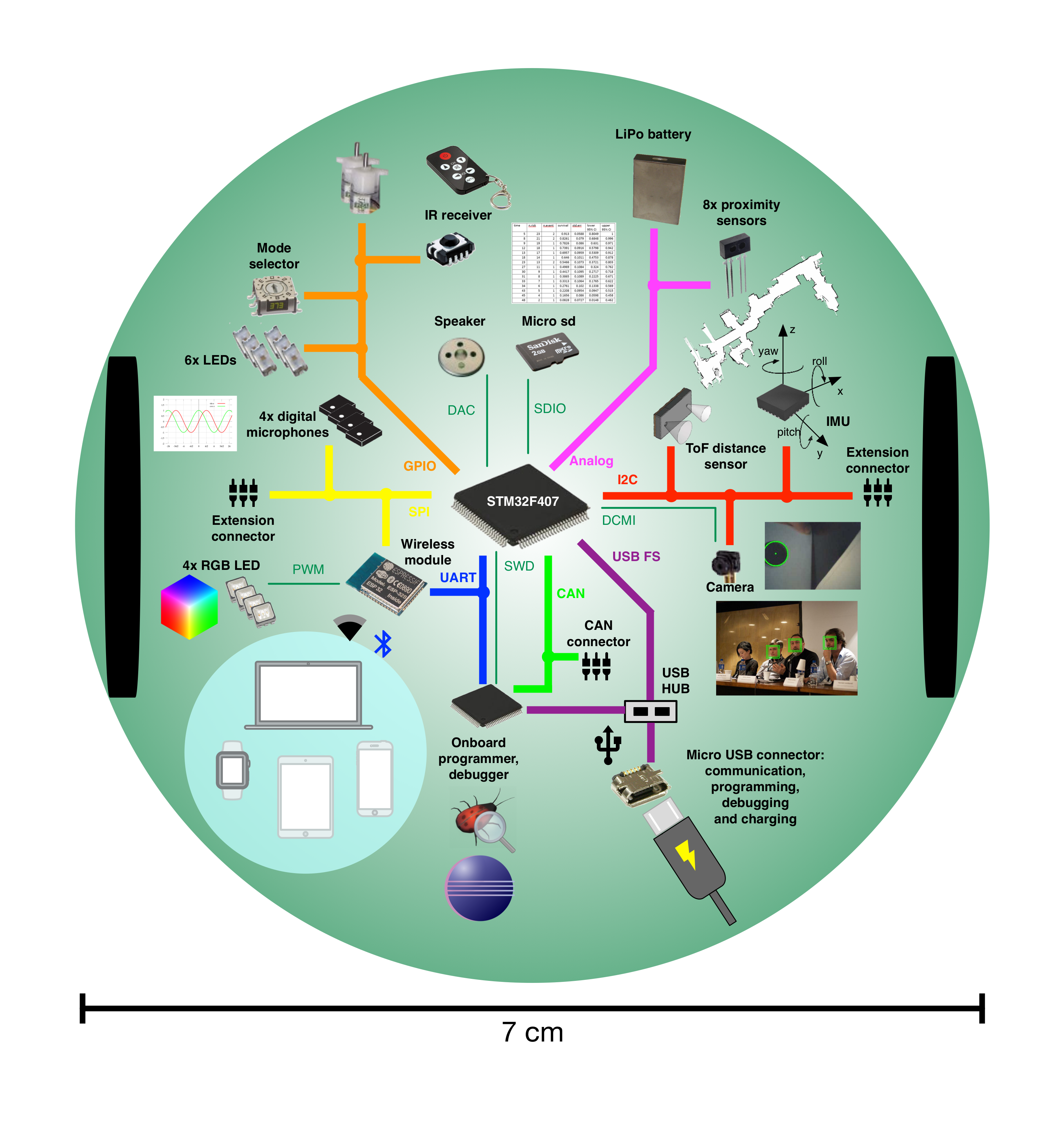
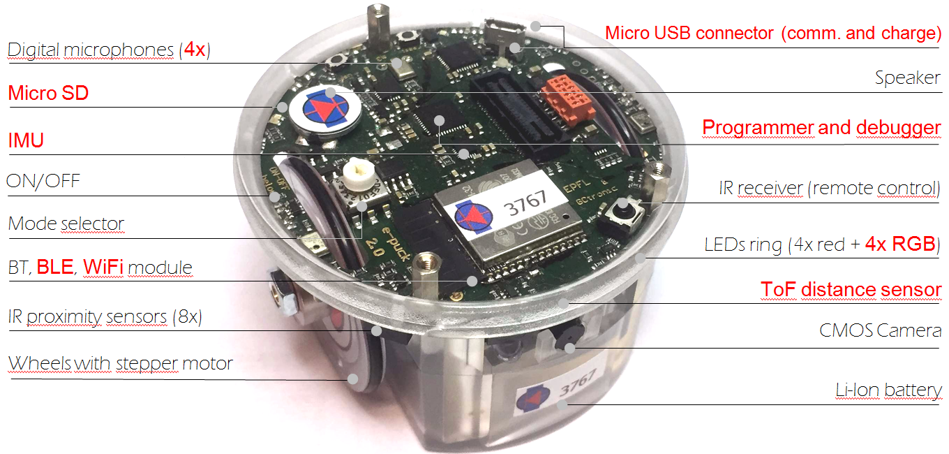
The following figures show the main components offered by the e-puck2 robot and where they are physically placed:
Specifications
The e-puck2 robot maintains full compatibility with its predecessor e-puck (e-puck HWRev 1.3 is considered in the following table):
| Feature | e-puck1.3 | e-puck2 | Compatibility | Additional |
| Size, weight | 70 mm diameter, 55 mm height, 150 g | Same form factor: 70 mm diameter, 45 mm, 130 g | No e-jumper required | |
| Battery, autonomy | LiIPo rechargeable battery (external charger), 1800 mAh. About 3 hours autonomy. Recharging time about 2-3h. |
Same battery; USB charging, recharging time about 2.5h. | USB charging | |
| Processor | 16-bit dsPIC30F6014A @ 60MHz (15 MIPS), DSP core for signal processing | 32-bit STM32F407 @ 168 MHz (210 DMIPS), DSP and FPU, DMA | ~10 times faster | |
| Memory | RAM: 8 KB; Flash: 144 KB | RAM: 192 KB; Flash: 1024 KB | RAM: 24x more capable Flash:~7x more capable | |
| Motors | 2 stepper motors with a 50:1 reduction gear; 20 steps per revolution; about 0.13 mm resolution | Same motors | ||
| Wheels | Wheels diamater = 41 mm Distance between wheels = 53 mm |
Same wheels | ||
| Speed | Max: 1000 steps/s (about 12.9 cm/s) | Max: 1200 steps/s (about 15.4 cm/s) | 20% faster | |
| Mechanical structure | Transparent plastic body supporting PCBs, battery and motors | Same mechanics | ||
| Distance sensor | 8 infra-red sensors measuring ambient light and proximity of objects up to 6 cm | Same infra-red sensors Front real distance sensor, Time of fight (ToF), up to 2 meter. |
ToF sensor | |
| IMU | 3D accelerometer and 3D gyro | 3D accelerometer, 3D gyro, 3D magnetometer | 3D magnetometer | |
| Camera | VGA color camera; typical use: 52x39 or 480x1 | Same camera; typical use: 160x120 | Bigger images handling | |
| Audio | 3 omni-directional microphones for sound localization speaker capable of playing WAV or tone sounds |
4 omni-directional microhpones (digital) for sound localization speaker capable of playing WAV or tone sounds |
+1 front microphone | |
| LEDs | 8 red LEDs around the robot, green body light, 1 strong red LED in front | 4 red LEDs and 4 RGB LEDs around the robot, green light, 1 strong red LED in front | 4x RGB LEDs | |
| Communication | RS232 and Bluetooth 2.0 for connection and programming | USB Full-speed, Bluetooth 2.0, BLE, WiFi | WiFi, BLE | |
| Storage | Not available | Micro SD slot | Micro SD | |
| Remote Control | Infra-red receiver for standard remote control commands | Same receiver | ||
| Switch / selector | 16 position rotating switch | Same selector | ||
| Extensions | Ground sensors, range and bearing, RGB panel, Gumstix extension, omnivision, your own | All extension supported | ||
| Programming | Free C compiler and IDE, Webots simulator, external debugger | Free C compiler and IDE, Webots simulator, onboard debugger (GDB) | Onboard debugger |
This is the overall communication schema:
Documentation
- Main microcontroller: STM32F407, datasheet, reference-manual
- Programmer/debugger: STM32F413, datasheet, reference-manual
- Radio module: Espressif ESP32, datasheet, reference-manual
- Camera: PixelPlus PO8030D CMOS image sensor, datasheet, no IR cut filter
- From about July 2019, the camera mounted on the e-puck2 robot is the Omnivision OV7670 CMOS image sensor, datasheet
- Microphones: STM-MP45DT02, datasheet
- Optical sensors: Vishay Semiconductors Reflective Optical Sensor, datasheet
- ToF distance sensor: STM-VL53L0X, datasheet, user-manual
- IMU: InvenSense MPU-9250, product-specification, register-map
- Motors: details
- Speaker: Diameter 13mm, power 500mW, 8 Ohm, DS-1389 or PSR12N08AK or similar
- IR receiver: TSOP36230
Migrating from e-puck1.x to e-puck2
The e-puck2 robot maintains full compatibility with its predecessor e-puck, but there are some improvements that you should be aware of.
First of all the e-jumper, that is the small board that is attached on top of the e-puck1.x, isn't anymore needed in the e-puck2. The components available on the e-jumper are integrated directly in the robot board. On top of the e-puck2 you'll see a quite big free connector, this is used to attach the extensions board designed for the e-puck1.x that are fully compatible with the e-puck2; you must not connect the e-jumper in this connector.
Secondly you don't need anymore to unplug and plugin the battery for charging, but instead you can charge the battery (up to 1 ampere) directly by connecting the USB cable. If you want you can still charge the battery with the e-puck1.x external charger, in case you have more than one battery.
Moreover you don't need anymore a special serial cable (with probably an RS232 to USB adapter) to be able to communicate with the robot, but you can use the USB cable. Once connected to the computer a serial port will be available that you can use to easily exchange data with the robot.
Extensions
All the extensions (ground sensors, range and bearing, RGB panel, gumstix and omnvision) are supported by the e-puck2 robot, this means that if you have some extensions for the e-puck1.x you can still use them also with e-puck2.
For more information about using the gumstix extension with e-puck2 robot refer to http://www.gctronic.com/doc/index.php?title=Overo_Extension#e-puck2.
Getting Started
The e-puck2 robot features 3 chips onboard:
- the main microcontroller, that is responsible for handling the sensors and actuators and which runs also the demos/algorithms
- the programmer, that provides programming/debugging capabilties and moreover it configures the USB hub and is responsible for the power management (on/off of the robot and battery measure)
- radio module, that is responsible for handling the wireless communication (WiFi, BLE, BT), the RGB LEDs and the user button (the RGB LEDs and button are connected to the radio module due to the pin number limitation on the main microcontroller)
The robot is shipped with the last firmware version programmed on all 3 chips, so you can immediately start using the robot.
The following sections explain the basic usage of the robot, all the users should read this chapter completely in order to have a minimal working system ready to play with the e-puck2 robot. Some sections will have more detailed information that can be read by following the links provided.
When required, dedicated informations are given for all platforms (Windows, Linux, Mac). The commands given for Linux are related to the Ubuntu distribution, similar commands are available in other distributions.
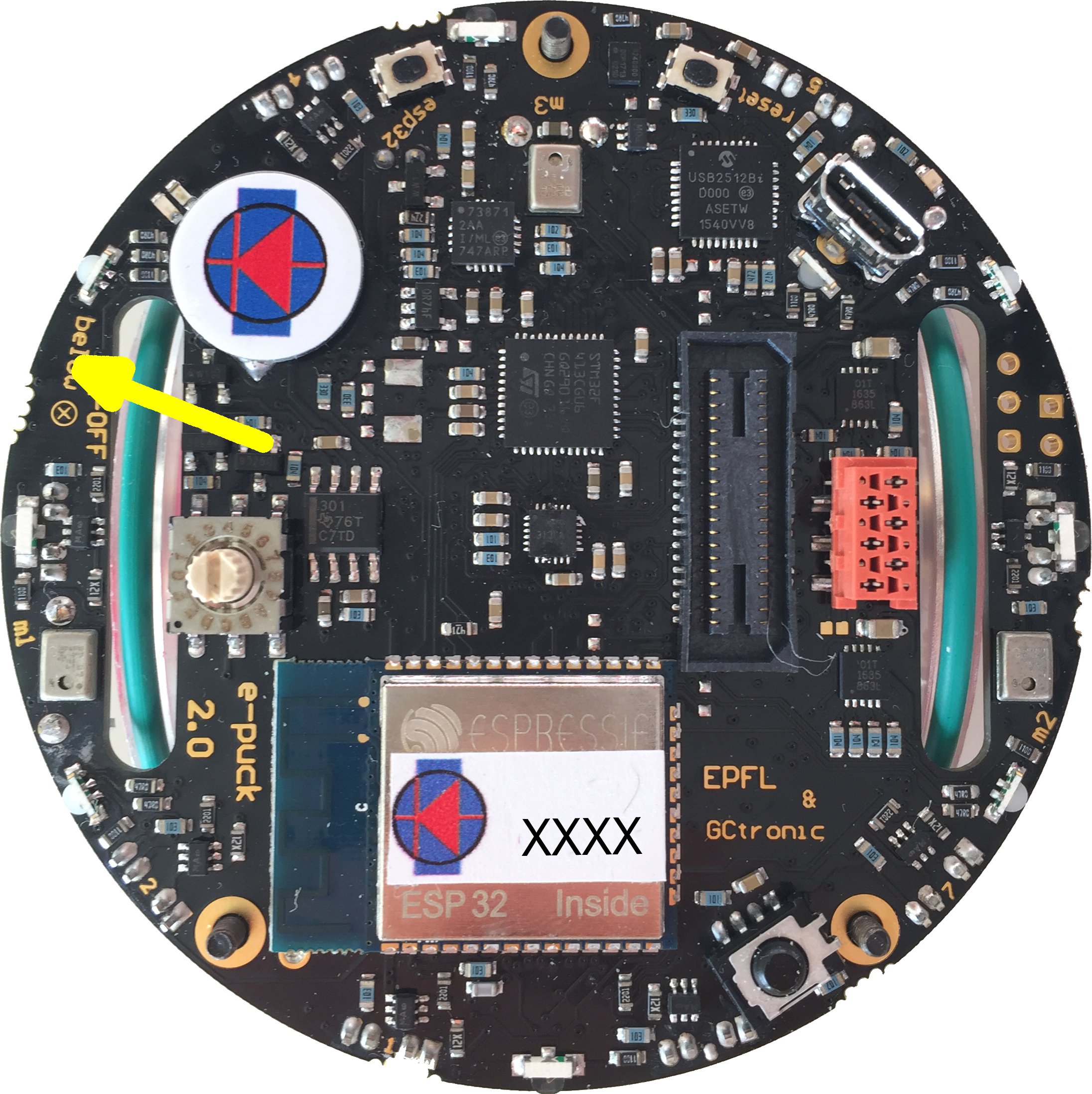
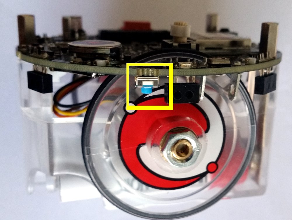
Turn on/off the robot
To turn on the robot you need to press the power button (blue button) placed on the bottom side of the board, near the speaker, as shown in the following figures:
To turn off the robot you need to press the power button for 1 second.
Meaning of the LEDs
The e-puck2 has three groups of LEDs that are not controllable by the user.
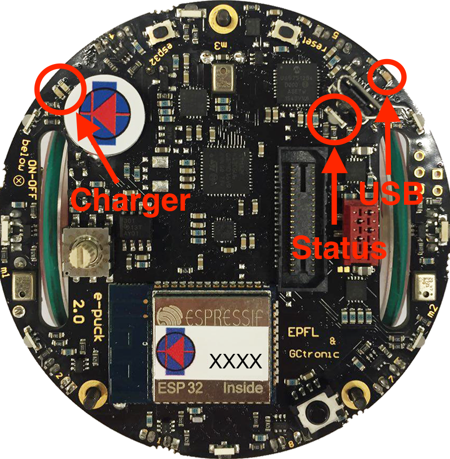
- Top view of the e-puck2
- Charger: RED if charging, GREEN if charge complete and RED and GREEN if an error occurs
- USB: Turned ON if the e-puck2 detects a USB connection with a computer
- STATUS: Turned ON if the robot is ON and OFF if the robot is OFF. When ON, gives an indication of the level of the battery. Also blinks GREEN if the program is running during a debug session.
Battery level indications (STATUS RGB LED):
- GREEN if the system's tension is greater than 3.5V
- ORANGE if the system's tension is between 3.5V and 3.4V
- RED if the system's tension is between 3.4V and 3.3V
- RED blinking if the system's tension is below 3.3V
The robot is automatically turned OFF if the system's tension gets below 3.2V during 10 seconds.
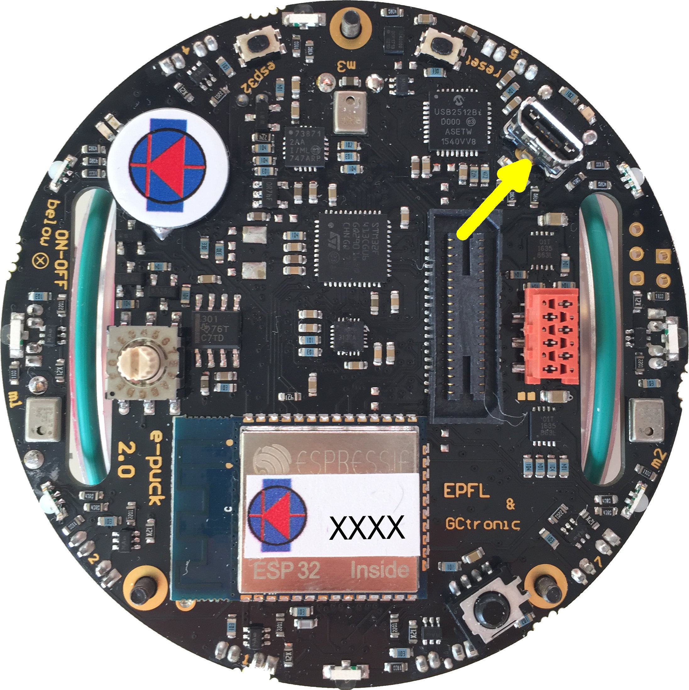
Connecting the USB cable
A micro USB cable (included with the robot in the package) is needed to connect the robot to the computer. There are two connectors, one placed on top of the robot facing upwards and the other placed on the side of the robot, as shown in the following figures. Both can be used to charge the robot (up to 1 ampere) or to communicate with it, but do not connect two cables at the same time. Connect the USB cable where is more comfortable to you.
Installing the USB drivers
The USB drivers must be installed only for the users of a Windows version older than Windows 10:
- Download and open zadig-2.3.exe
- Connect the e-puck2 with the USB cable and turn it on. Three unknown devices appear in the device list of the program, namely e-puck2 STM32F407, e-puck2 GDB Server (Interface 0) and e-puck2 Serial Monitor (Interface 2).
- For each of the three devices mentioned above, select the
USB Serial (CDC)driver and click on theInstall Driverbutton to install it. Accept the different prompts which may appear during the process. At the end you can simply quit the program and the drivers are installed. These steps are illustrated on Figure 3 below.
- Note : The drivers installed are located in
C:\Users\"your_user_name"\usb_driver
- Note : The drivers installed are located in
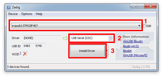
- Example of driver installation for e-puck2 STM32F407
The drivers are automatically installed with Windows 10, Linux and Mac OS.
Anyway in Linux in order to access the serial ports, a little configuration is needed. Type the following command in a terminal session: sudo adduser $USER dialout. Once done, you need to log off to let the change take effect.
Finding the USB serial ports used
Two ports are created by the e-puck2's programmer when the USB cable is connected to the robot (even if the robot is turned off):
- e-puck2 GDB Server. The port used to program and debug the e-puck2.
- e-puck2 Serial Monitor. Serial communication between the PC and the radio module (used also to program the radio module).
A third port could be available depending on the code inside the e-puck2's microcontroller. With the factory firmware a port named e-puck2 STM32F407 is created.
Windows
- Open the Device Manager
- Under Ports (COM & LPT) you can see the virtual ports connected to your computer.
- Do a Right-click -> properties on the COM port you want to identify.
- Go under the details tab and select Bus reported device description in the properties list.
- The name of the port should be written in the text box below.
- Once you found the desired device, you can simply look at its port number (COMX).
Linux
- 1. Open a terminal window (
ctrl+alt+t) and enter the following command:ls /dev/ttyACM* - 2. Look for ttyACM0 and ttyACM1 in the generated list, which are respectively e-puck2 GDB Server and e-puck2 Serial Monitor. ttyACM2 will be also available with the factory firmware, that is related to e-puck2 STM32F407 port
Note : Virtual serial port numbering on Linux depends on the connections order, thus it can be different if another device using virtual serial ports is already connected to your computer before connecting the robot, but the sequence remains the same.
Mac
- 1. Open a terminal window and enter the following command:
ls /dev/cu.usbmodem* - 2. Look for two cu.usbmodemXXXX, where XXXX is the number attributed by your computer. You should find two names, with a numbering near to each other, which are respectively e-puck2 GDB Server (lower number) and e-puck2 Serial Monitor (higher number). A third device cu.usbmodemXXXX will be available with the factory firmware, that is related to e-puck2 STM32F407 port
Note : Virtual serial port numbering on Mac depends on the physical USB port used and the device. If you want to keep the same names, you must connect to the same USB port each time.
PC interface
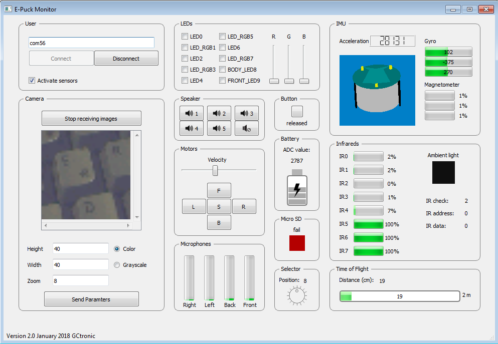
A PC application was developed to start playing with the robot attached to the computer via USB cable: you can have information about all the sensors, receive camera images and control the leds and motors.
Beware that it's not mandatory to download this application in order to work with the robot, but it is a nice demo that gives you an overview of all the sensors and actuators available on the robot, this is a first step to gain confidence with the robot.
With the factory firmwares programmed in the robot, place the selector in position 8, attach the USB cable and turn on the robot. Enter the correct port (the one related to e-puck2 STM32F407) in the interface and click connect.
The source code is available from the repository https://github.com/e-puck2/monitor.
Available executables
- Windows executable: tested on Windows 7 and Windows 10
- Max OS X executable
- Ubuntu 14.04 (or later) - 64 bit
On Linux remember to apply the configuration explained in the chapter Installing the USB drivers in order to access the serial port.
Installing the dependencies for firmwares updates
You can update the firmware for all 3 chips: the main microcontroller, the radio module and the programmer. For doing that, you need some tools to be installed on the system.
Windows
To upload a new firmware in the microcontroller or in the radio module, you don't need to install anything, the packages provided include all the dependencies.
To upload a new firmware in the programmer you need to install an application called DfuSe released by STMicroelectronics. You can download it from DfuSe_V3.0.5.zip.
Linux
To upload a new firmware in the microcontroller or in the radio module, you need:
- Python (>= 3.4):
sudo apt-get install python3 - Python pip:
sudo apt-get install -y python3-pip - pySerial (>= 2.5):
sudo pip3 install pyserial
To upload a new firmware in the programmer you need:
- dfu-util:
sudo apt-get install dfu-util
Mac
Install the Homewbrew package manager by opening a terminal and issueing:
/usr/bin/ruby -e "$(curl -fsSL https://raw.githubusercontent.com/Homebrew/install/master/install)"
and then:
brew upgrade
To upload a new firmware in the microcontroller or in the radio module, you need:
- Python (>= 3.4):
brew install python(it will install alsopip) - pySerial (>= 2.5):
pip3 install pyserial
To upload a new firmware in the programmer you need:
- dfu-util:
brew install dfu-util
PC side development
This section is dedicated to the users that develop algorithms on the PC side and interact with the robot remotely through a predefined communication protocol. These users don't modify the firmware of the robot, but instead they use the factory firmware released with the robot. They update the robot firmware only when there is an official update.
The remote control of the robot, by receiving sensors values and setting the actuators, is done through the following channels: Bluetooth, Bluetooth Low Energy, WiFi, USB cable.
Examples of tools/environment used by these users:
- Aseba
- Simulator (e.g. Webots)
- ROS
- iOS, Android apps
- Custom PC application
- IoT (e.g. IFTTT)
If you fall into this category, then follow this section for more information: PC side development.
Main microcontroller
The e-puck2 robot main microcontroller is a 32-bit STM32F407 that runs at 168 MHz (210 DMIPS) and include DSP, FPU and DMA capabilities. The version chosen for the e-puck2 has 192 KB of total RAM and 1024 KB of flash, so there is a lot of memory to work with.
This chip is responsible for handling the sensors and actuators and runs also the demos and algorithms.
Factory firmware
The main microcontroller of the robot is initially programmed with a firmware that includes many demos that could be started based on the selector position, here is a list of the demos with related position and a small description:
- Selector position 0: Aseba
- Selector position 1: Shell
- Selector position 2: Read proximity sensors and when an object is near a proximity, turn on the corresponding LED
- Selector position 3: Asercom protocol v2 (BT)
- Selector positoin 4: Range and bearing extension (receiver)
- Selector position 5: Range and bearing extension - clustering demo (simultaneous transmitter and receiver).
- Selector position 6: Move the robot back and forth exploiting the gyro, with LEDs animation
- Selector position 7: Play a wav (mono, 16 KHz) named "example.wav" from the micro sd when pressing the button
- Selector position 8: Asercom protocol v2 (USB)
- Selector position 9: Local communication: transceiver
- Selector position 10: this position is used to work with the Linux extensions. To work with gumstix refer to Overo Extension: e-puck2 , to work with Pi-puck refer to Pi-puck: Requirements .
- Selector position 11: Simple obstacle avoidance + some animation
- Selector position 12: Hardware test
- Selector position 13: LEDs reflect orientation of the robot
- Selector position 14: Compass
- Selector position 15: WiFi mode
The pre-built firmware is available here main microcontroller factory firmware (10.12.21).
Firmware update
Now and then there could be an official firmware update for the robot and it's important to keep the robot updated with the last firmware to get possibile new features, improvements and for bug fixes.
The onboard programmer run a GDB server, so we use GDB commands to upload a new firmware, for this reason a toolchain is needed to upload a new firmware to the robot.
The following steps explain how to update the main microcontroller firmware:
1. Download the package containing the required toolchain and script to program the robot: Windows, Linux 32 bits/64 bits, Mac OS
2. Download the last version of the main microcontroller factory firmware (10.12.21), or use your custom firmware
3. Extract the package and put the firmware file (with elf extension) inside the package directory; beware that only one elf file must be present inside this directory
4. Attach the USB cable and turn on the robot
5. Run the script from the package directory:
- Windows: double click
program.bat - Linux/Mac: issue the following command in a terminal
./program.sh. If you get permission errors, then issuesudo chmod +x program.shto let the script be executable.
When the upload is complete you'll see an output like in the following figure:
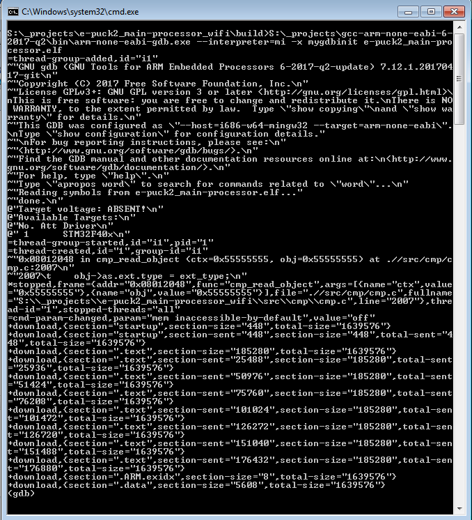
The final lines should contain the entry ".data",, this means that the upload was successfull. You can then close the terminal window if it is still open.
If you encounter some problem, try to unplug and plug again the USB cable and power cycle the robot, then retry.
Robot side development
If you are an embedded developer and are brave enough, then you have complete access to the source code running on the robot, so you can discover what happen inside the main microcontroller and modify it to accomodate your needs. Normally the users that fall into this category develop algorithms optimized to run directly on the microcontroller, such as:
- onboard image processing
- swarm algorithms
- fully autonomous behaviors
- ...
For more information about programming the robot itself, refer to section Robot side development
Radio module
The radio module chosen for the e-puck is the new ESP32 chip from Espressif, integrating a dual core that run up to 240 MHz, 4 MB of flash and 520 KB of RAM. It supports WiFi standards 802.11 b/g/n (access point mode supported), Bluetooth and Bluetooth LE 4.2. It is the successor of the ESP8266 chip. The following figure shows the various peripherals available on the ESP32:
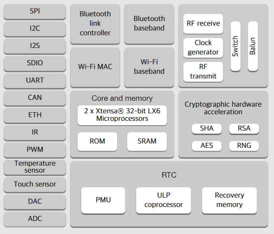
This chip first of all is responsible for handling the wireless communication, moreover it handles also the RGB LEDs (with PWM) and the user button. The RGB LEDs and button are connected to the radio module due to the pin number limitation on the main microcontroller.
Factory firmware
The radio module of the robot is initially programmed with a firmware that supports Bluetooth communication.
The pre-built firmware is available here radio module factory firmware (11.12.18).
WiFi firmware
At the moment the factory firmware supports only Bluetooth, if you want to work with WiFi you need to program the radio with a dedicated firmware, refer to section PC side development: WiFi.
BLE firmware
At the moment the factory firmware supports only calssic Bluetooth, if you want to work with Bluetooth Low Energy you need to program the radio with a dedicated firmware, refer to section Mobile phone development.
Firmware update
In order to update the firmware of the ESP32 WiFi module you need to use a python script called esptool provided by Espressif (manufacturer of the chip). This script was modified to work with the e-puck2 robot and is included in the provided package. The following steps explain how to update the radio module firmware:
1. Download the package containing the required tools and script to program the robot: Windows, Linux / Mac
2. Download the last version of the radio module factory firmware (11.12.18), or use another firmware (e.g. WiFi, BLE, your own). The firmware is composed by 3 files named bootloader.bin, ESP32_E-Puck_2.bin and partitions_singleapp.bin
3. Extract the package and put the firmware files inside the package directory; beware that the name of the .bin files must be the same as indicated in step 2
4. Attach the USB cable and turn on the robot
5. Run the script from the package directory:
- Windows: double click
program.bat - Linux/Mac: issue the following command in a terminal
./program.sh. If you get permission errors, then issuesudo chmod +x program.shto let the script be executable.
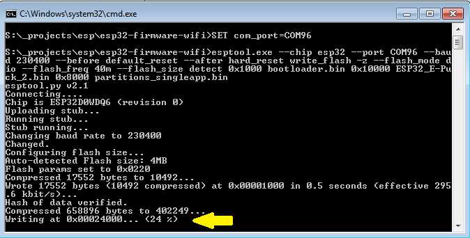
The upload should last about 10-15 seconds and you'll see the progress as shown in the following figure:
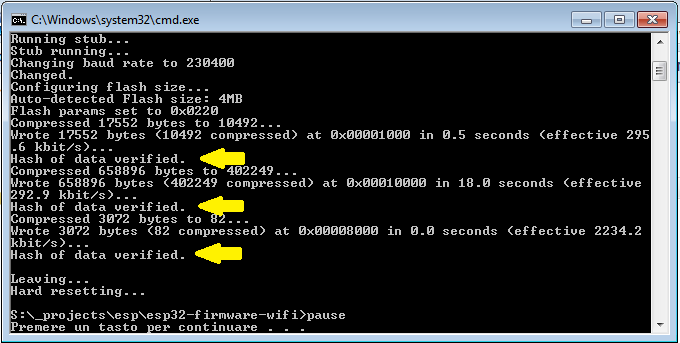
When the upload is complete you'll see that all 3 bin files are uploaded correctly as shown in the following figure:
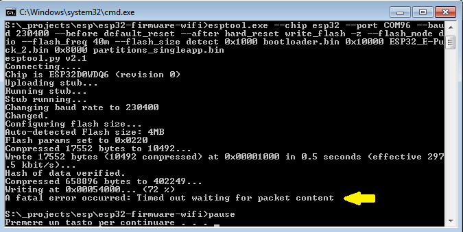
Sometime you could encounter a timeout error as shown in the following figures; in these cases you need to unplug and plug again the USB cable and power cycle the robot, then you can retry.
Development
Probably, you'll never need to touch the firmware running in the radio module, but in case you need to modify the code or you're simply curious about what is happening at the low level, then refer to the section Radio module development.
Programmer
The e-puck2 robot is equipped with an onboard programmer and debugger that let you update the firmware of the robot and debug your code easily using a standard USB interface. There is a dedicated STM32F413 microcontroller that acts as the programmer with built in GDB server, so you can control exactly what happens using the GNU Project Debugger in your host machine.
The programmer microcontroller is also in charge of handling various low level features such as the configuration of the USB hub and the power button.
Factory firmware
The programmer is initially programmed with a firmware based on a modified version of Black Magic Probe programmer/debugger.
The pre-built firmware is available here programmer-firmware.bin (28.05.20); it is also available in dfu format here programmer-firmware.dfu (28.05.20).
Firmware update
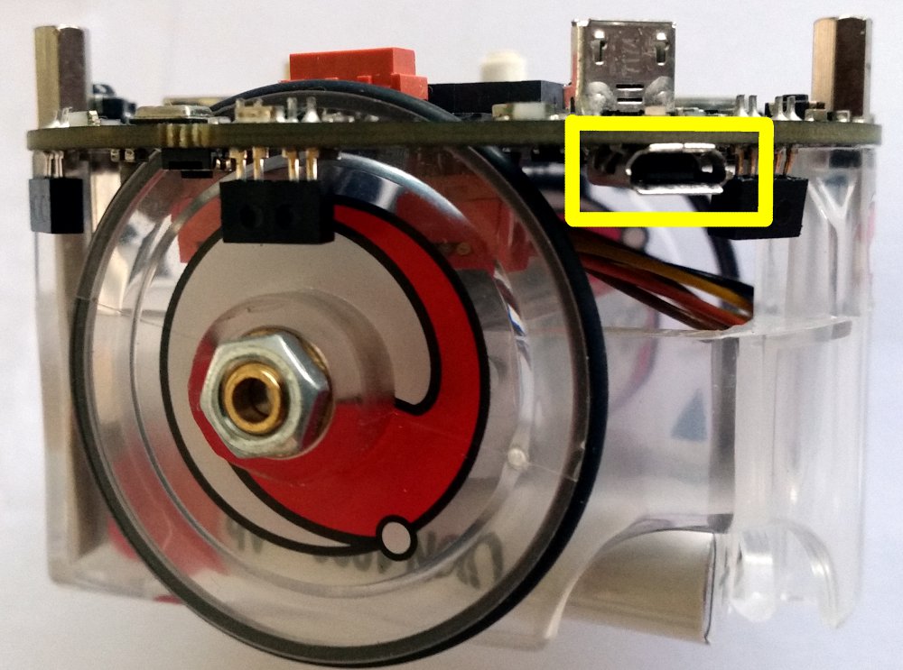
The programmer's microcontroller features a factory bootloader that can be entered by acting on some special pins, the bootloader mode is called DFU (device firmware upgrade). You can enter DFU mode by contacting two pinholes together while inserting the USB cable (no need to turn on the robot). The two pin holes are located near the USB connector of the e-puck2, see the photo below.
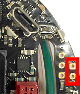
- Location of the pin holes to put the programmer into DFU
The programmer will be recognized as STM Device in DFU Mode device.
Note for Windows users: the device should be recognized automatically (in all Windows versions), but in case it won't be detected then you need to install a libusbK driver for the DFU device.
Follow the same procedure as explained in section Installing the USB drivers using libusbK driver instead of USB Serial (CDC).
Linux/Mac
In order to update the programmer firmware you need an utility called dfu-util, it should be already installed from section Installing the dependencies for firmwares updates.
To uplaod the firmware, issue the following command: sudo dfu-util -d 0483:df11 -a 0 -s 0x08000000 -D programmer-firmware.bin
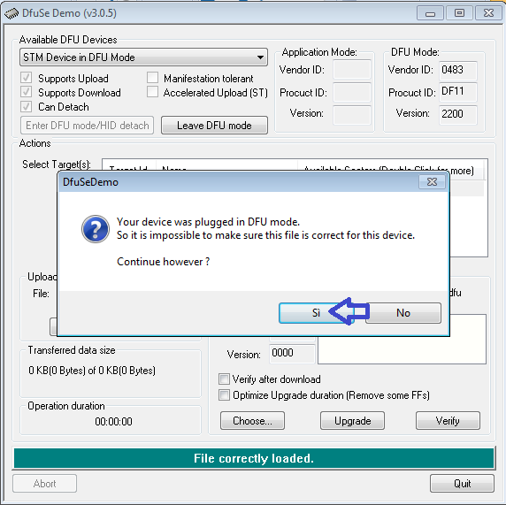
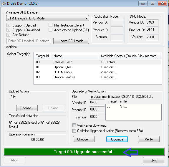
Windows
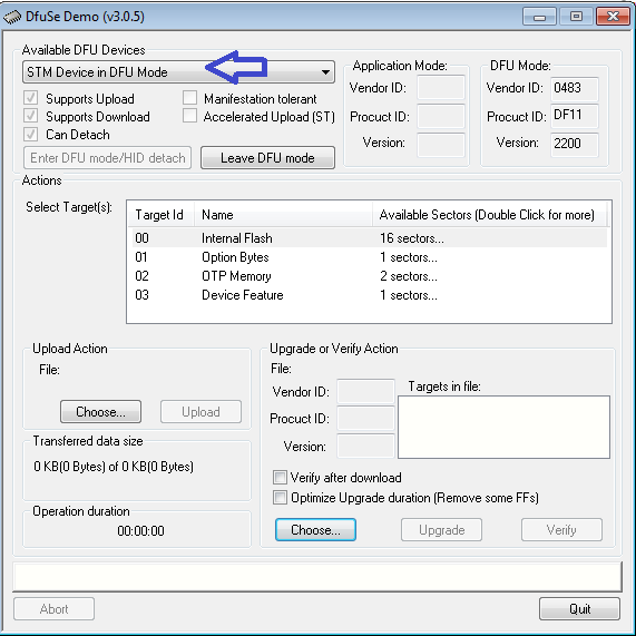
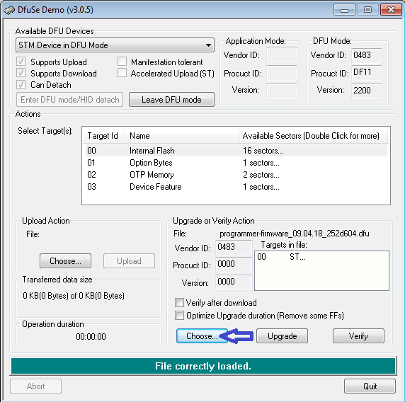
Start the DfuSe application (previously installed from section Installing the dependencies for firmwares updates). The programmer in DFU mode will be automatically detected as shown in figure 1. Then you need to open the compiled firmware by clicking on choose and then locating the file with dfu extension, as shown in figure 2. Now click on the upgrade button, a warning message will be shown, confirm the action by clicking on yes as shown in figure 3. If all is ok you'll be prompted with a message saying that the upgrade was successfull as shown in figure 4.
| [1] | [2] | [3] | [4] |
 |
 |
 |
 |
Development
The programmer code shouldn't be modified, but if you know what you're doing then refer to section Programmer development.