Elisa-3 and Pi-puck: Difference between pages
| Line 1: | Line 1: | ||
=Hardware= | =Hardware= | ||
==Overview== | |||
<span class="plainlinks">[https:// | <span class="plainlinks">[https://projects.gctronic.com/epuck2/wiki_images/pipuck-overview.jpg <img width=600 src="https://projects.gctronic.com/epuck2/wiki_images/pipuck-overview-small.jpg">]</span><br/> | ||
Features: | |||
* Raspberry Pi Zero W or Zero 2 W connected to the robot via I2C | |||
* interface between the robot base camera and the rPi via USB, up to 15 FPS | |||
* 1 digital microphone and 1 speaker | |||
* USB hub connected to the rPi with 2 free ports | |||
* uUSB cable to the rPi uart port. Also ok for charging | |||
* 2 chargers. 1 for the robot battery and 1 for the auxiliary battery on top of the extension | |||
* charging contact points in front for automatic charging. External docking station available | |||
* several extension options. 6 i2C channels, 2 ADC inputs | |||
* several LED to show the status of the rPi and the power/chargers | |||
== | ==I2C bus== | ||
I2C is used to let communicate various elements present in the robot, Pi-puck and extensions. An overall schema is shown in the following figure:<br/> | |||
<span class="plainlinks">[https:// | <span class="plainlinks">[https://projects.gctronic.com/epuck2/wiki_images/i2c-buses.png <img width=600 src="https://projects.gctronic.com/epuck2/wiki_images/i2c-buses.png">]</span><br/> | ||
An I2C switcher is included in the Pi-puck extension in order to support additional I2C buses (the RPi alone has only one usable I2C bus). These are needed to avoid conflicts between Time-of-Flight sensors that have a fixed I2C address. | |||
= | =Getting started= | ||
This introductory section explains the minimal procedures needed to work with the Raspberry Pi Zero W / Zero 2 W mounted on the Pi-puck extension board and gives a general overview of the available basic demos and scripts shipped with the system flashed on the micro SD. More advanced demos are described in the following separate sections (e.g. ROS), but the steps documented here are fundamental, so be sure to fully understand them. <br/> | |||
The extension is mostly an interface between the e-puck robot and the Raspberry Pi, so you can exploit the computational power of a Linux machine to extend the robot capabilities.<br/> | |||
The | |||
In most cases, the Pi-puck extension will be attached to the robot, but it's interesting to note that it can be used also alone when the interaction with the robot isn't required.<br/> | |||
The | The following sections assume the full configuration (robot + extension), unless otherwise stated. | ||
==Requirements== | |||
The robot must be programmed with a special firmware in order to communicate via I2C bus with the Raspberry Pi mounted on the Pi-puck extension. The same I2C bus is shared by all the devices (camera, IMU, distance sensor, others extensions), the main microcontroller and the Raspberry Pi. Since the Raspberry Pi acts as I2C master, these devices will not be anymore reachable directly from the robot main microcontroller that will act instead as I2C slave. | |||
=== | ===e-puck version 1=== | ||
The | The e-puck version 1 robot must be programmed with the following firmware [https://raw.githubusercontent.com/yorkrobotlab/pi-puck/master/e-puck1/pi-puck-e-puck1.hex pi-puck-e-puck1.hex]. | ||
- | |||
- | |||
-- | |||
=== | ===e-puck version 2=== | ||
The robot | The e-puck version 2 robot must be programmed with the following firmware [https://projects.gctronic.com/epuck2/gumstix/e-puck2_main-processor_extension_b346841_07.06.19.elf e-puck2_main-processor_extension.elf (07.06.19)] and the selector must be placed in position 10(A).<br/> | ||
The source code is available in the <code>gumstix</code> branch of the repo <code>https://github.com/e-puck2/e-puck2_main-processor</code>. | |||
==Turn on/off the extension== | |||
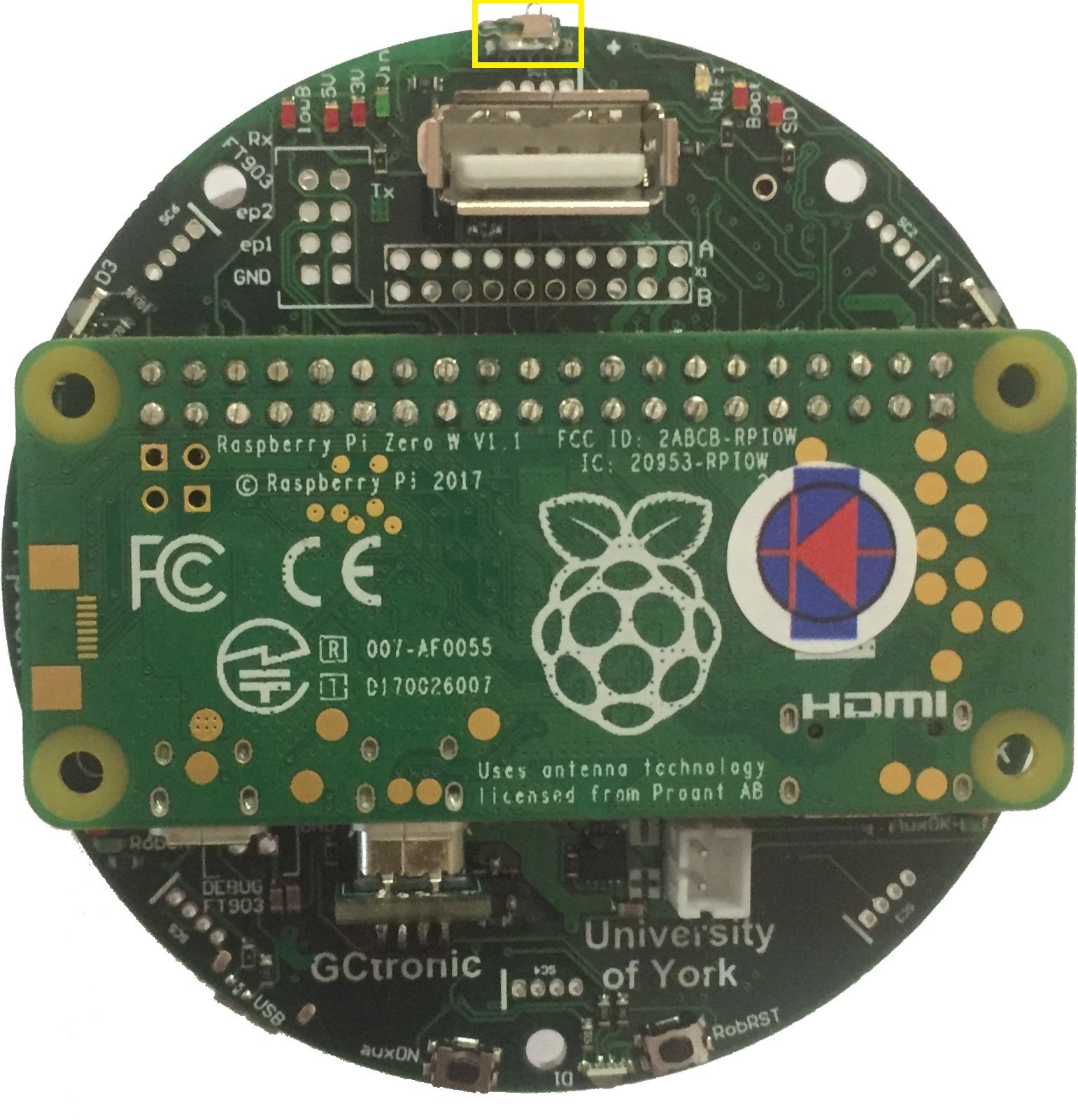
To turn on the extension you need to press the <code>auxON</code> button as shown in the follwoing figure; this will turn on also the robot (if not already turned on). Similarly, if you turn on the robot then also the extension will turn on automatically.<br/> | |||
<span class="plainlinks">[https://projects.gctronic.com/epuck2/wiki_images/pipuck_btn_on_off.jpg <img width=250 src="https://projects.gctronic.com/epuck2/wiki_images/pipuck_btn_on_off-small.jpg">]</span><br/> | |||
To turn off the Pi-puck you need to press and hold the <code>auxON</code> button for 2 seconds; this will initiate the power down procedure.<br> | |||
Beware that by turning off the robot, the extension will not be turned off automatically if it is powered from another source like the micro usb cable or a secondary battery. You need to use its power off button to switch it off. Instead if there is no other power source, then by turning off the robot also the extension will be turned off (not cleanly). | |||
==Console mode== | |||
The Pi-puck extension board comes with a pre-configured system ready to run without any additional configuration.<br/> | |||
In order to access the system from a PC in console mode, the following steps must be performed:<br/> | |||
1. connect a micro USB cable from the PC to the extension module. If needed, the drivers are available in the following link [https://www.silabs.com/products/development-tools/software/usb-to-uart-bridge-vcp-drivers USB to UART bridge drivers]<br/> | |||
<span class="plainlinks">[https://projects.gctronic.com/epuck2/wiki_images/pipuck_usb.png <img width=250 src="https://projects.gctronic.com/epuck2/wiki_images/pipuck_usb-small.png">]</span><br/> | |||
2. execute a terminal program and configure the connection with 115200-8N1 (baudrate, 8 bits, no flow control). The serial device is the one created when the extension is connected to the computer<br/> | |||
3. switch on the robot (the extension will turn on automatically); now the terminal should display the Raspberry Pi booting information. If the robot isn't present, then you can directly power on the extension board with the related button<br/> | |||
4. login with <code>user = pi</code>, <code>password = raspberry</code><br/> | |||
==Battery charge== | |||
You can either charge the robot battery or the additional battery connected to the Pi-puck extension or both the batteries by simply plugging the micro USB cable.<br/> | |||
The following figure shows the connector for the additional battery.<br/> | |||
<span class="plainlinks">[https://projects.gctronic.com/epuck2/wiki_images/pipuck_battery.jpg <img width=250 src="https://projects.gctronic.com/epuck2/wiki_images/pipuck_battery-small.jpg">]</span><br/> | |||
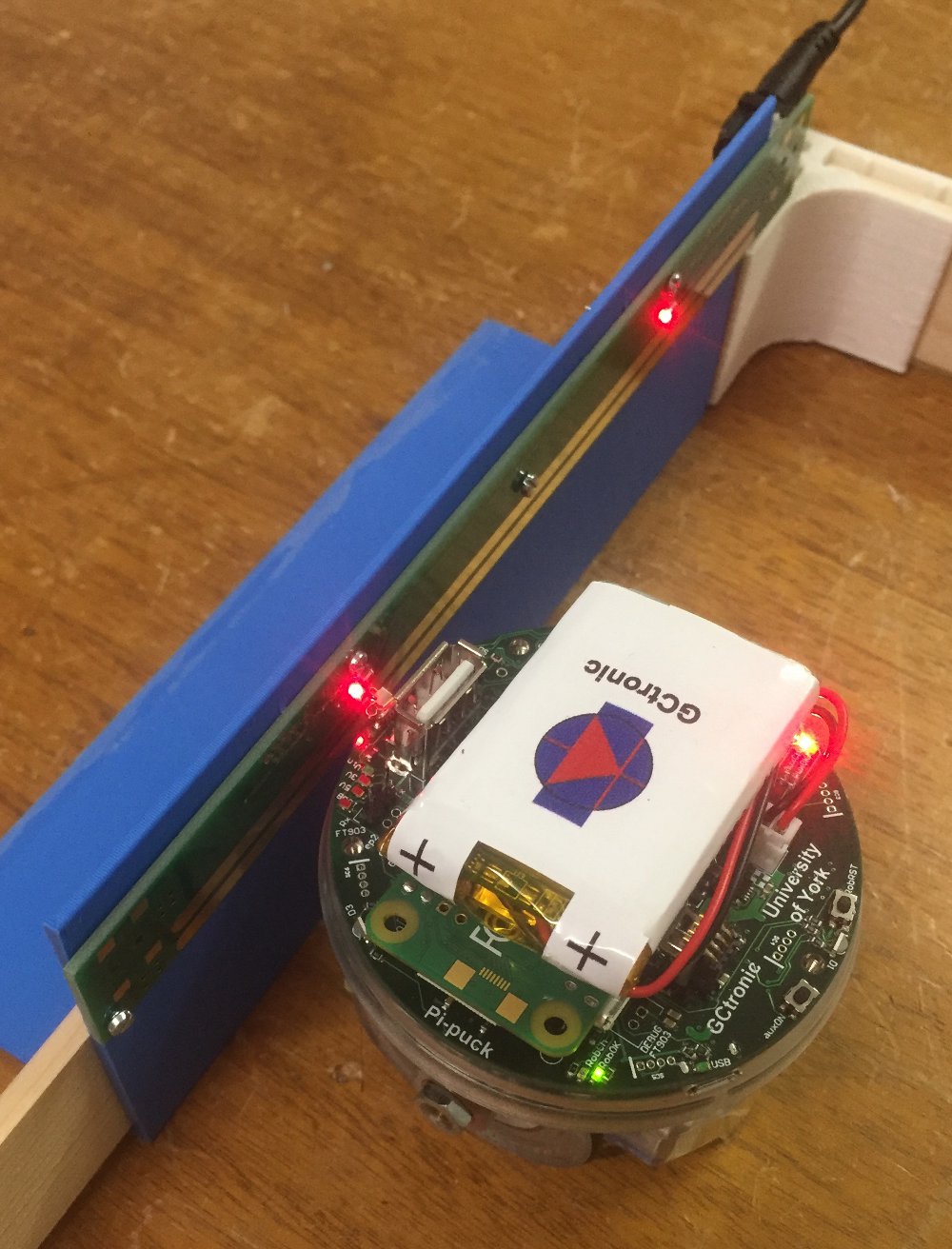
The robot can also autonomously charge itself if the charging wall is available. The Pi-puck extension includes two spring contacts on the front side that let the robot easily make contact with the charging wall and charge itself. The charging wall and the spring contacts are shown in the following figures:<br/> | |||
<span class="plainlinks">[https://www.gctronic.com/img2/shop/pipuck-charger-robot.jpg <img width=250 src="https://www.gctronic.com/img2/shop/pipuck-charger-robot-small.jpg">]</span> | |||
<span class="plainlinks">[https://projects.gctronic.com/epuck2/wiki_images/pipuck_contacts.jpg <img width=250 src="https://projects.gctronic.com/epuck2/wiki_images/pipuck_contacts-small.jpg">]</span><br/> | |||
== | ==Reset button== | ||
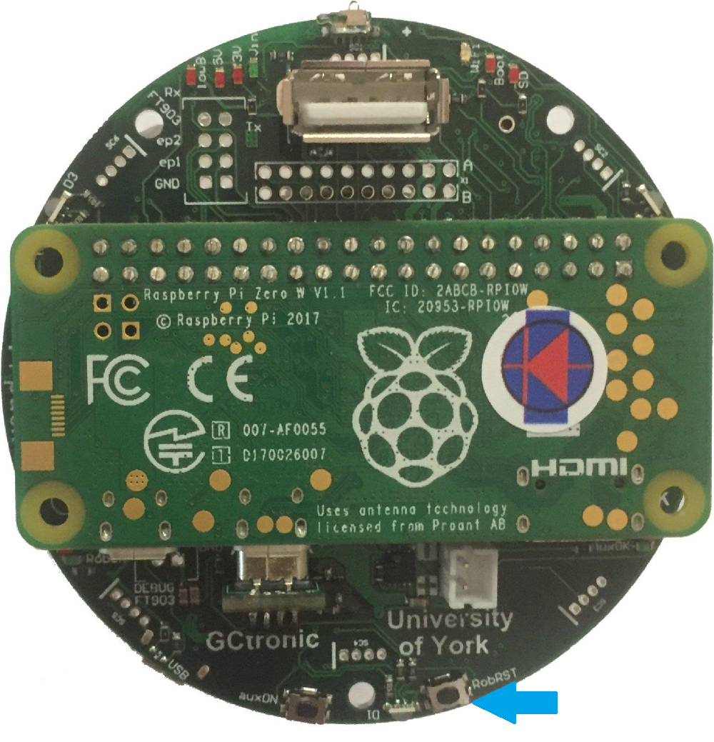
A button is available to reset the robot, when pressed it will resets only the robot restarting its firmware. This is useful for instance during development or for specific demos in which a restart of the robot is needed. In these cases you don't need to turn off completely the robot (and consequently also the Pi-puck if energy is supplied by the robot) but instead you can simply reset the robot. The position of the reset button is shown in the following figure:<br/> | |||
<span class="plainlinks">[https://projects.gctronic.com/epuck2/wiki_images/pipuck_reset.png <img width=250 src="https://projects.gctronic.com/epuck2/wiki_images/pipuck_reset-small.png">]</span><br/> | |||
=How to communicate with the robot and its sensors= | |||
==Communicate with the e-puck version 1== | |||
Refer to the repo [https://github.com/yorkrobotlab/pi-puck-e-puck1 https://github.com/yorkrobotlab/pi-puck-e-puck1]. | |||
= | ==Communicate with the e-puck version 2== | ||
An example showing how to exchange data between the robot and the Pi-puck extension is available in the Pi-puck repository; you can find it in the directory <code>/home/pi/Pi-puck/e-puck2/</code>.<br/> | |||
You can build the program with the command <code>gcc e-puck2_test.c -o e-puck2_test</code>.<br/> | |||
Now you can run the program by issueing <code>./e-puck2_test</code>; this demo will print the sensors data on the terminal and send some commands to the robot at 2 Hz.<br/> | |||
The same example is also available in Python, you can run it by issueing <code>python3 e-puck2_test.py</code>. | |||
== | ===Packet format=== | ||
Extension to robot packet format, 20 bytes payload (the number in the parenthesis represents the bytes for each field): | |||
{| border="1" | |||
| Left speed (2) | |||
| Right speed (2) | |||
| Speaker (1) | |||
| LED1, LED3, LED5, LED7 (1) | |||
| LED2 RGB (3) | |||
| LED4 RGB (3) | |||
| LED6 RGB (3) | |||
| LED8 RGB (3) | |||
| Settings (1) | |||
| Checksum (1) | |||
|} | |||
* Left, right speed: [-2000 ... 2000] | |||
* Speaker: sound id = [0, 1, 2] | |||
* LEDs on/off flag: bit0 for LED1, bit1 for LED3, bit2 for LED5, bit3 for LED7 | |||
* RGB LEDs: [0 (off) ... 100 (max)] | |||
* Settings: | |||
** bit0: 1=calibrate IR proximity sensors | |||
** bit1: 0=disable onboard obstacle avoidance; 1=enable onboard obstacle avoidance (not implemented yet) | |||
** bit2: 0=set motors speed; 1=set motors steps (position) | |||
* Checksum: Longitudinal Redundancy Check (XOR of the bytes 0..18) | |||
= | Robot to extension packet format, 47 bytes payload (the number in the parenthesis represents the bytes for each field): | ||
{| border="1" | |||
| 8 x Prox (16) | |||
| 8 x Ambient (16) | |||
| 4 x Mic (8) | |||
| Selector + button (1) | |||
| Left steps (2) | |||
| Right steps (2) | |||
| TV remote (1) | |||
| Checksum | |||
|} | |||
* Selector + button: selector values represented by 4 least significant bits (bit0, bit1, bit2, bit3); button state is in bit4 (1=pressed, 0=not pressed) | |||
* Checksum: Longitudinal Redundancy Check (XOR of the bytes 0..45) | |||
==== | ==Communicate with the IMU== | ||
===e-puck version 1=== | |||
An example written in C showing how to read data from the IMU (LSM330) mounted on e-puck version 1.3 is available in the Pi-puck repository; you can find it in the directory <code>/home/pi/Pi-puck/e-puck1/</code>.<br/> | |||
You can build the program with the command <code>gcc e-puck1_imu.c -o e-puck1_imu</code>.<br/> | |||
Now you can run the program by issueing <code>./e-puck1_imu</code> and then choose whether to get data from the accelerometer or gyroscope; this demo will print the sensors data on the terminal.<br/> | |||
=== | ===e-puck version 2=== | ||
An example showing how to read data from the IMU (MPU-9250) is available in the Pi-puck repository; you can find it in the directory <code>/home/pi/Pi-puck/e-puck2/</code>.<br/> | |||
You can build the program with the command <code>gcc e-puck2_imu.c -o e-puck2_imu</code>.<br/> | |||
Now you can run the program by issueing <code>./e-puck2_imu</code> and then choose whether to get data from the accelerometer or gyroscope; this demo will print the sensors data on the terminal.<br/> | |||
The same example is also available in Python, you can run it by issueing <code>python3 e-puck2_imu.py</code>. | |||
== | ==Communicate with the ToF sensor== | ||
The Time of Flight sensor is available only on the e-puck version 2 robot.<br/> | |||
First of all you need to verify that the VL53L0X Python package is installed with the following command: <code>python3 -c "import VL53L0X"</code>. If the command returns nothing you're ready to go, otherwise if you receive an <code>ImportError</code> then you need to install the package with the command: <code>pip3 install git+https://github.com/gctronic/VL53L0X_rasp_python</code>.<br/> | |||
A Python example showing how to read data from the ToF sensor is available in the Pi-puck repository; you can find it in the directory <code>/home/pi/Pi-puck/e-puck2/</code>.<br/> | |||
You can run the example by issueing <code>python3 VL53L0X_example.py</code> (this is the example that you can find in the repository [https://github.com/gctronic/VL53L0X_rasp_python/tree/master/python https://github.com/gctronic/VL53L0X_rasp_python/tree/master/python]). | |||
==Capture an image== | |||
The robot camera is connected to the Pi-puck extension as a USB camera, so you can access it very easily.<br/> | |||
An example showing how to capture an image from the robot's camera using OpenCV is available in the Pi-puck repository; you can find it in the directory <code>/home/pi/Pi-puck/snapshot/</code>.<br/> | |||
You can build the program with the command <code>g++ $(pkg-config --libs --cflags opencv) -ljpeg -o snapshot snapshot.cpp</code>.<br/> | |||
Now you can run the program by issueing <code>./snapshot</code>; this will save a VGA image (JPEG) named <code>image01.jpg</code> to disk.<br/> | |||
The program can accept the following parameters:<br/> | |||
<code>-d DEVICE_ID</code> to specify the input video device from which to capture an image, by default is <code>0</code> (<code>/dev/video0</code>). This is useful when working also with the [http://www.gctronic.com/doc/index.php?title=Omnivision_Module_V3 Omnivision V3] extension that crates another video device; in this case you need to specify <code>-d 1</code> to capture from the robot camera.<br/> | |||
<code>-n NUM</code> to specify how many images to capture (1-99), by default is 1<br/> | |||
<code>-v</code> to enable verbose mode (print some debug information)<br/> | |||
Beware that in this demo the acquisition rate is fixed to 5 Hz, but the camera supports up to '''15 FPS'''.<br/> | |||
The same example is also available in Python, you can run it by issueing <code>python snapshot.py</code>. | |||
==Communicate with the ground sensors extension== | |||
Both e-puck version 1 and e-puck version 2 support the [https://www.gctronic.com/doc/index.php?title=Others_Extensions#Ground_sensors ground sensors extension].<br/> | |||
This extension is attached to the I2C bus and can be read directly from the Pi-puck.<br/> | |||
An example written in C showing how to read data from the ground sensors extension is available in the Pi-puck repository; you can find it in the directory <code>/home/pi/Pi-puck/ground-sensor/</code>.<br/> | |||
You can build the program with the command <code>gcc groundsensor.c -o groundsensor</code>.<br/> | |||
Now you can run the program by issueing <code>./groundsensor</code>; this demo will print the sensors data on the terminal.<br/> | |||
The same example is also available in Python, you can run it by issueing <code>python3 groundsensor.py</code>. | |||
==Communicate with the range and bearing extension== | |||
Both e-puck version 1 and e-puck version 2 support the [https://www.gctronic.com/doc/index.php?title=Others_Extensions#Range_and_bearing range and bearing extension].<br/> | |||
This extension is attached to the I2C bus and can be read directly from the Pi-puck.<br/> | |||
An example written in C showing how to start playing with the range and bearing extension is available in the Pi-puck repository; you can find it in the directory <code>/home/pi/Pi-puck/randb/</code>. You need two boards: one is the transmitter (run <code>randb_tx</code>) and the other is the receiver (run <code>randb_rx</code>). The receiver will print the data received from the transmitter.<br/> | |||
You can build the programs with the command <code>gcc randb_tx.c -o randb_tx</code> and <code>gcc randb_rx.c -o randb_rx</code>.<br/> | |||
The same example is also available in Python, you can run it by issueing <code>python3 randb_tx.py</code> and <code>python3 randb_rx.py</code>.<br/> | |||
For best performances you need also to take in consideration the interference given by the time of flight and proximity sensors (see [https://www.gctronic.com/doc/index.php?title=Others_Extensions#e-puck_2 https://www.gctronic.com/doc/index.php?title=Others_Extensions#e-puck_2]). | |||
If you want to have | ==Wireless remote control== | ||
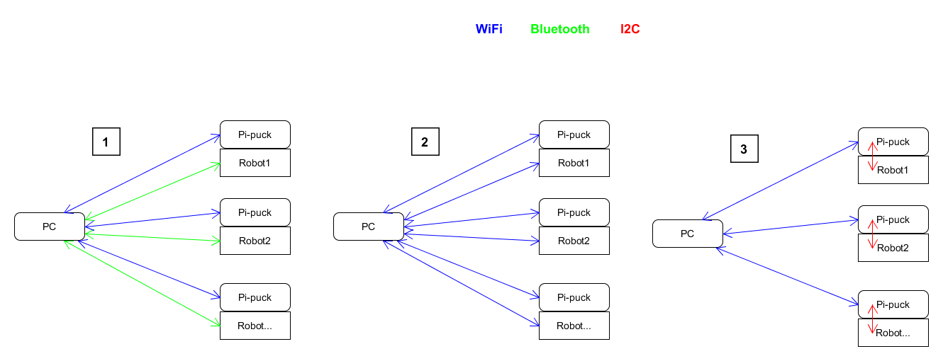
If you want to control the robot from a computer, for instance when you have an algorithm that requires heavy processing not suitable for the Pi-puck or when the computer acts as a master controlling a fleet of robots that return some information to the controller, then you have 3 options:<br/> | |||
1) The computer establishes a WiFi connection with the Pi-puck to receive data processed by the Pi-puck (e.g. results of an image processing task); at the same time the computer establishes a Bluetooth connection directly with the e-puck version 2 robot to control it. | |||
:''Disadvantages'': | |||
:- the Bluetooth standard only allow up to seven simultaneous connections | |||
:- doubled latency (Pi-puck <-> pc and pc <-> robot) | |||
2) The computer establishes a WiFi connection with both the Pi-puck and the e-puck version 2 robot. | |||
:''Advantages'': | |||
:- only one connection type needed, easier to handle | |||
:''Disadvantages'': | |||
:- doubled latency (Pi-puck <-> pc and pc <-> robot) | |||
3) The computer establishes a WiFi connection with the Pi-puck and then the Pi-puck is in charge of controlling the robot via I2C based on the data received from the computer controller. | |||
:''Advantages'': | |||
:- less latency involved | |||
:- less number of connections to handle | |||
:- depending on your algorithm, it would be possible to initially develop the controller on the computer (easier to develop and debug) and then transfer the controller directly to the Pi-puck without the need to change anything related to the control of the robot via I2C | |||
< | The following figure summarizes these 3 options:<br/> | ||
< | <span class="plainlinks">[https://projects.gctronic.com/epuck2/wiki_images/wireless-remote-control-options.png <img width=600 src="https://projects.gctronic.com/epuck2/wiki_images/wireless-remote-control-options.png">]</span> | ||
=== | =How to work with the Pi-puck= | ||
==Demos and scripts update== | |||
First of all you should update to the last version of the demos and scripts released with the system that you can use to start playing with the Pi-puck extension and the robot.<br/> | |||
To update the repository follow these steps:<br/> | |||
1. go to the directory <code>/home/pi/Pi-puck</code><br/> | |||
2. issue the command <code>git pull</code><br/> | |||
Then to update some configurations of the system:<br/> | |||
1. go to the directory <code>/home/pi/Pi-puck/system</code><br/> | |||
2. issue the command <code>./update.sh</code>; the system will reboot.<br/> | |||
You can find the Pi-puck repository here [https://github.com/gctronic/Pi-puck https://github.com/gctronic/Pi-puck].<br/> | |||
== | ==Audio recording== | ||
< | Use the <code>arecord</code> utility to record audio from the onboard microphone. The following example shows how to record an audio of 2 seconds (<code>-d</code> parameter) and save it to a wav file (<code>test.wav</code>):<br/> | ||
<code>arecord -Dmic_mono -c1 -r16000 -fS32_LE -twav -d2 test.wav</code><br/> | |||
You can also specify a rate of 48 KHz with <code>-r48000</code> | |||
== | ==Audio play== | ||
< | Use <code>aplay</code> to play <code>wav</code> files and <code>mplayer</code> to play <code>mp3</code> files. | ||
==Battery reading== | |||
A Python example showing how to measure both the battery of the robot and the battery of the Pi-puck extension is available in the Pi-puck repository; you can find it in the directory <code>/home/pi/Pi-puck/battery/</code>.<br/> | |||
You can start reading the batteries values by issueing <code>python read-battery.py</code>.; this demo will print the batteries values (given in Volts) on the terminal.<br/> | |||
An additional Python example is provided in the same directory showing how to detect when the robot is in charge: this is a basic demo in which the robot goes forward and stop only when it is in charge, it can be used as a starting point for more advanced examples. To run this demo issue the commands <code>sudo pigpiod</code> and then <code>python3 goto-charge.py</code>. | |||
==WiFi configuration== | |||
{ | Specify your network configuration in the file <code>/etc/wpa_supplicant/wpa_supplicant-wlan0.conf</code>.<br/> | ||
Example:<br/> | |||
<pre> | |||
ctrl_interface=DIR=/var/run/wpa_supplicant GROUP=netdev | |||
update_config=1 | |||
country=CH | |||
network={ | |||
ssid="MySSID" | |||
psk="9h74as3xWfjd" | |||
} | |||
</pre> | |||
You can have more than one <code>network</code> parameter to support more networks. For more information about ''wpa_supplicant'' refer to [https://hostap.epitest.fi/wpa_supplicant/ https://hostap.epitest.fi/wpa_supplicant/]. | |||
Once the configuration is done, you can also connect to the Pi-puck with <code>SSH</code>. If you are working in Windows you can use [https://www.putty.org/ PuTTY]. | |||
=== | ===How to know your IP address=== | ||
A simple method to know your IP address is to connect the USB cable to the Pi-puck extension and issue the command <code>ip a</code>; from the command's result you will be able to get you current assigned IP address. | |||
If you | If you prefer to know your IP address remotely (without connecting any cable) then you can use <code>nmap</code>.<br/> | ||
For example you can search all connected devices in your network with the following command: <code>nmap 192.168.1.*</code>. Beware that you need to specify the subnet based on your network configuration.<br/> | |||
From the command's result you need to look for the hostname <code>raspberrypi</code>.<br/> | |||
If you are working in Windows you can use the [https://nmap.org/zenmap/ Zenmap] application. | |||
< | ==File transfer== | ||
< | ===USB cable=== | ||
You can transfer files via USB cable between the computer and the Pi-puck extension by using on of the <code>zmodem</code> protocol.<br/> | |||
The <code>lrzsz</code> package is pre-installed in the system, thus you can use the <code>sx</code> and <code>rx</code> utilities to respectevely send files to the computer and receive files from the computer.<br/> | |||
Example of sending a file to the computer using the <code>Minicom</code> terminal program:<br/> | |||
1. in the Pi-puck console type <code>sx --zmodem fliename.ext</code>. The transfer should start automatically and you'll find the file in the home directory.<br/> | |||
<!--2. to start the transfer type the sequence <code>CTRL+A+R</code>, then chose <code>xmodem</code> and finally enter the name you want to assign to the received file. You'll find the file in the home directory.<br/>--> | |||
Example of receiving a file from the computer using the <code>Minicom</code> terminal program:<br/> | |||
1. in the Pi-puck console type <code>rx -Z</code><br/> | |||
2. to start the transfer type the sequence <code>CTRL+A+S</code>, then chose <code>zmodem</code> and select the file you want to send with the <code>spacebar</code>. Finally press <code>enter</code> to start the transfer.<br/> | |||
===WiFi=== | |||
The Pi-puck extension supports <code>SSH</code> connections.<br/> | |||
To exchange files between the Pi-puck and the computer, the <code>scp</code> tool (secure copy) can be used. An example of transferring a file from the Pi-puck to the computer is the following:<br/> | |||
<code>scp pi@192.168.1.20:/home/pi/example.txt example.txt</code> | |||
If you are working in Windows you can use [https://www.putty.org/ PuTTY]. | |||
==== | ==Image streaming== | ||
==Bluetooth LE== | |||
An example of a ''BLE uart service'' is available in the Pi-puck repository; you can find it in the directory <code>/home/pi/Pi-puck/ble/</code>.<br/> | |||
To start the service you need to type: <code>python uart_peripheral.py</code>.<br/> | |||
Then you can use the ''e-puck2-android-ble app'' you can find in chapter [https://www.gctronic.com/doc/index.php?title=e-puck2_mobile_phone_development#Connecting_to_the_BLE Connecting to the BLE] in order to connect to the Pi-puck extension via BLE. Once connected you'll receive some dummy data for the proximity values and by clicking on the motion buttons you'll see the related action printed on the Pi-puck side. This is a starting point that you can extend based on your needs. | |||
= | =Operating system= | ||
The | The system is based on Raspbian Stretch and can be downloaded from the following link [https://projects.gctronic.com/epuck2/PiPuck/pi-puck-os_25.05.22.zip pi-puck-os_25.05.22.zip]. | ||
When booting the first time, the first thing to do is expanding the file system in order to use all the available space on the micro sd:<br/> | |||
1. <code>sudo raspi-config</code><br/> | |||
2. Select <code>Advanced Options</code> and then <code>Expand Filesystem</code><br/> | |||
3. reboot | |||
== | ==e-puck version 2 camera configuration== | ||
The | The e-puck version 2 camera need to be configured through I2C before it can be used. For this reason a Python script is called at boot that detects and configures the camera. The script resides in the Pi-puck repository installed in the system (<code>/home/pi/Pi-puck/camera-configuration.py</code>), so beware to not remove it. | ||
If the robot is plugged after the boot process is completed, you need to call manually the Python configuration script before using the camera by issueing the command <code>python3 /home/pi/Pi-puck/camera-configuration.py</code>. | |||
< | |||
In order to automatically run the script at boot, the <code>/etc/rc.local</code> was modified by adding the call to the script just before the end of the file. | |||
In | |||
== | ==Power button handling== | ||
The power button press is handled by a background service (<code>systemd</code>) started automatically at boot. The service description file is located in <code>/etc/systemd/system/power_handling.service</code> and it calls the <code>/home/pi/power-handling/</code> program. Beware to not remove neither of these files.<br/> | |||
The source code of the power button handling program is available in the Pi-puck repository and is located in <code>/home/pi/Pi-puck/power-handling/power-handling.c</code>. | |||
== | ==Desktop mode== | ||
The system starts in console mode, to switch to desktop (LXDE) mode issue the command <code>startx</code>. | |||
=== | ===Camera viewer=== | ||
A camera viewer called <code>luvcview</code> is installed in the system. You can open a terminal and issue simply the command <code>luvcview</code> to see the image coming from the robot camera. | |||
== | ==VNC== | ||
[https://www.realvnc.com/en/ VNC] is a remote control desktop application that lets you connect to the Pi-puck from your computer and then you will see the desktop of the Pi-puck inside a window on your computer. You'll be able to control it as though you were working on the Pi-puck itself.<br/> | |||
VNC is installed in the system and the ''VNC server'' is automatically started at boot, thus you can connect with ''VNC Viewer'' from your computer by knowing the IP address of the Pi-puck (refer to section [https://www.gctronic.com/doc/index.php?title=Pi-puck#How_to_know_your_IP_address How to know your IP address]).<br/> | |||
Notice that the ''VNC server'' is started also in console mode. | |||
== | ==I2C communication== | ||
The | The communication between the Pi-puck extension and the robot is based on I2C. The system is configured to exploit the I2C hardware peripheral in order to save CPU usage, but if you need to use the software I2C you can enable it by modifying the <code>/boot/config.txt</code> file and removing the <code>#</code> symbol (comment) in front of the line with the text <code>dtparam=soft_i2c</code> (it is placed towards the end of the file). | ||
< | |||
< | |||
==Audio output configuration== | |||
You can enable or disable audio output by modifying the <code>config.txt</code> file in the <code>boot</code> partition.<br/> | |||
To enable audio output insert the line: <code>gpio=22=op,dh</code><br/> | |||
To disable audio output insert the line: <code>gpio=22=op,dl</code><br/> | |||
If you don't need to play audio files it is suggested to disable audio output in order to save power. | |||
= | =ROS= | ||
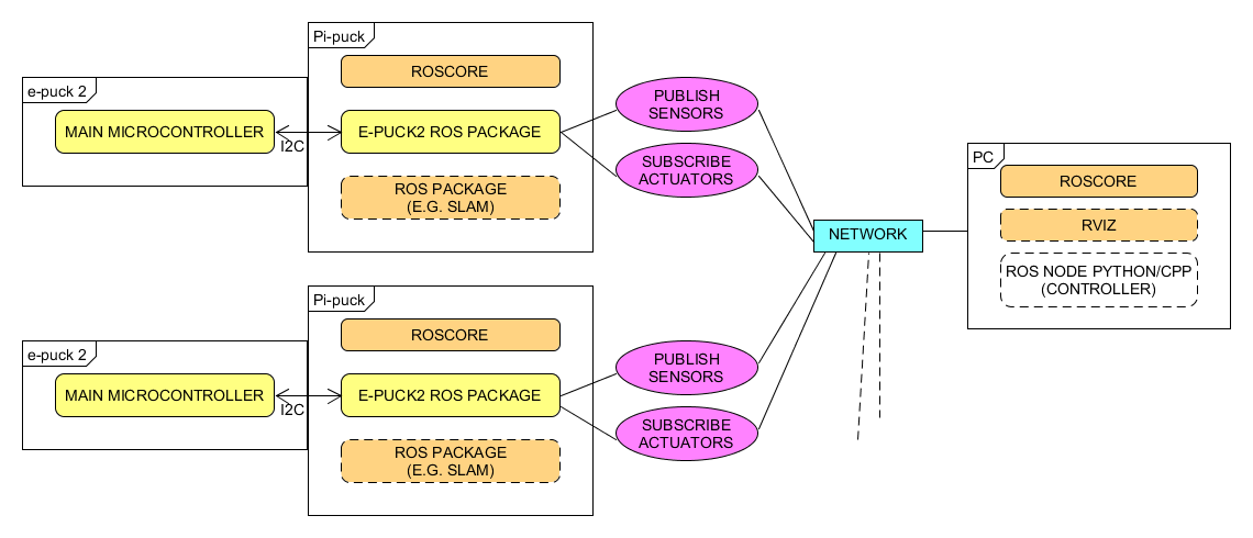
ROS Kinetic is integrated in the Pi-puck system.<br/> | |||
A ROS node developed to run in the Pi-puck is available for both <code>CPP</code> and <code>Python</code>, the communication system is based on the third architecture shown in chapter [https://www.gctronic.com/doc/index.php?title=Pi-puck#Wireless_remote_control Wireless remote control]; a more detailed schema is shown below:<br/> | |||
<span class="plainlinks">[https://projects.gctronic.com/epuck2/wiki_images/epuck2-ros-schema.png <img width=600 src="https://projects.gctronic.com/epuck2/wiki_images/epuck2-ros-schema.png">]</span> | |||
==Initial configuration== | |||
The ROS workspace is located in <code>~/rosbots_catkin_ws/</code><br/> | |||
The e-puck version 2 ROS driver is located in <code>~/rosbots_catkin_ws/src/epuck_driver_cpp/</code><br/> | |||
Remember to follow the steps in the section [http://www.gctronic.com/doc/index.php?title=Pi-puck#Requirements Requirements ] and section [https://www.gctronic.com/doc/index.php?title=Pi-puck#Demos_and_scripts_update Demos and scripts update], only once.<br/> | |||
The PC (if used) and the Pi-puck extension are supposed to be configured in the same network. | |||
==== | ==Running roscore== | ||
<code>roscore</code> can be launched either from the PC or directly from the Pi-puck.<br/> | |||
Before starting roscore, open a terminal and issue the following commands: | |||
* | * <code>export ROS_IP=roscore-ip</code> | ||
* | * <code>export ROS_MASTER_URI=http://roscore-ip:11311</code> | ||
where <code>roscore-ip</code> is the IP of the machine that runs <code>roscore</code><br/> | |||
Then start <code>roscore</code> by issueing <code>roscore</code>. | |||
== | ==Running the ROS node== | ||
Before starting the e-puck version 2 ROS node on the Pi-puck, issue the following commands: | |||
* <code>export ROS_IP=pipuck-ip</code> | |||
* <code>export ROS_MASTER_URI=http://roscore-ip:11311</code> | |||
where <code>pipuck-ip</code> is the IP of the Pi-puck extension and <code>roscore-ip</code> is the IP of the machine that runs <code>roscore</code> (can be the same IP if <code>roscore</code> runs directly on the Pi-puck). | |||
To start the e-puck version 2 ROS node issue the command:<br/> | |||
<code>roslaunch epuck_driver_cpp epuck_minimal.launch debug_en:=true ros_rate:=20</code><br/> | |||
<!-- | |||
To start the e-puck version 2 ROS node issue the command:<br/> | |||
<code>roslaunch epuck_driver_cpp epuck_controller.launch epuck_id:='3000'</code><br/> | |||
This launch file will start the e-puck2 node and the camera node. | |||
If you are using a PC, then you can start <code>rviz</code>: | |||
* in a terminal issue the command <code>rviz rviz</code> | |||
* open the configuration file named <code>single_epuck_driver_rviz.rviz</code> you can find in <code>epuck_driver_cpp/config/</code> directory | |||
--> | |||
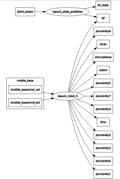
The following graph shows all the topics published by the e-puck version 2 driver node:<br/> | |||
<span class="plainlinks">[https://projects.gctronic.com/epuck2/wiki_images/ros-e-puck2_.jpg <img width=150 src="https://projects.gctronic.com/epuck2/wiki_images/ros-e-puck2_small.jpg">]</span> | |||
''<font size="2">Click to enlarge</font>'' | |||
== | ==Test the communication== | ||
You can test if the communication between the robot and the computer is actually working by simply display messages published by a topic, e.g.:<br/> | |||
<code>rostopic echo /proximity0</code><br/> | |||
You can have the list of all the topics by issuing the command: <code>rostopic list</code>.<br/> | |||
You can move the robot straight forward by issuing <code>rostopic pub -1 /mobile_base/cmd_vel geometry_msgs/Twist -- '[4.0, 0.0, 0.0]' '[0.0, 0.0, 0.0]'</code>.<br/> | |||
You can rotate the robot on the spot by issuing <code>rostopic pub -1 /mobile_base/cmd_vel geometry_msgs/Twist -- '[0.0, 0.0, 0.0]' '[0.0, 0.0, 1.0]'</code>.<br/> | |||
You can change the LEDs state by issuing <code>rostopic pub -1 /mobile_base/cmd_led std_msgs/UInt8MultiArray "{data: [LED1, LED3, LED5, LED7]}"</code>, e.g. <code>rostopic pub -1 /mobile_base/cmd_led std_msgs/UInt8MultiArray "{data: [1, 1, 1, 1]}"</code> to turn them all on.<br/> | |||
== | ==Get the source code== | ||
The last version of the e-puck version 2 ROS node can be downloaded from the git: <code>git clone -b pi-puck https://github.com/gctronic/epuck_driver_cpp.git</code><br/> | |||
To update to the last version follow these steps: | |||
# <code>cd ~/rosbots_catkin_ws/src/</code> | |||
# <code>rm -R -f epuck_driver_cpp</code> | |||
# <code>git clone -b pi-puck https://github.com/gctronic/epuck_driver_cpp.git</code> | |||
# <code>cd ~/rosbots_catkin_ws/</code> | |||
# <code>catkin_make --only-pkg-with-deps epuck_driver_cpp</code> | |||
= | ==Python version== | ||
A Python version developed by the York University can be found here [https://github.com/yorkrobotlab/pi-puck-ros https://github.com/yorkrobotlab/pi-puck-ros]. | |||
=ROS 2= | |||
ROS2 Foxy running on Raspberry Pi OS Buster is available in the following link [https://drive.google.com/file/d/150bHaXz-NGelogcMq1AlOrvf-U5tPT_g/view?usp=sharing ros2_foxy_epuck2.img]. | |||
= | |||
==Running ROS 2 node== | |||
To start the robot node issue the command <code>ros2 run epuck_ros2_driver driver</code>.<br/> | |||
To start the camera node issue the command <code>ros2 run epuck_ros2_camera camera</code>. | |||
< | |||
==Test the communication== | |||
{{ | You can test if the communication between the robot and the computer is actually working by simply display messages published by a topic, e.g.:<br/> | ||
<code>ros2 topic echo /tof</code><br/> | |||
You can have the list of all the topics by issuing the command: <code>ros2 topic list</code>.<br/> | |||
You can move the robot straight forward by issuing <code>ros2 topic pub -1 /cmd_vel geometry_msgs/Twist "{linear:{x: 2.0, y: 0.0, z: 0.0}, angular:{x: 0.0, y: 0.0, z: 0.0}}"</code>.<br/> | |||
You can change the LEDs state by issuing <code>ros2 topic pub -1 /led0 std_msgs/msg/Bool "{data: true}"</code>. | |||
== | ==Get the source code== | ||
The last version of the e-puck version 2 ROS 2 node can be downloaded from the git: <code>git clone https://github.com/cyberbotics/epuck_ros2.git</code><br/> | |||
< | |||
=OpenCV= | |||
OpenCV 3.4.1 is integrated in the Pi-puck system. | |||
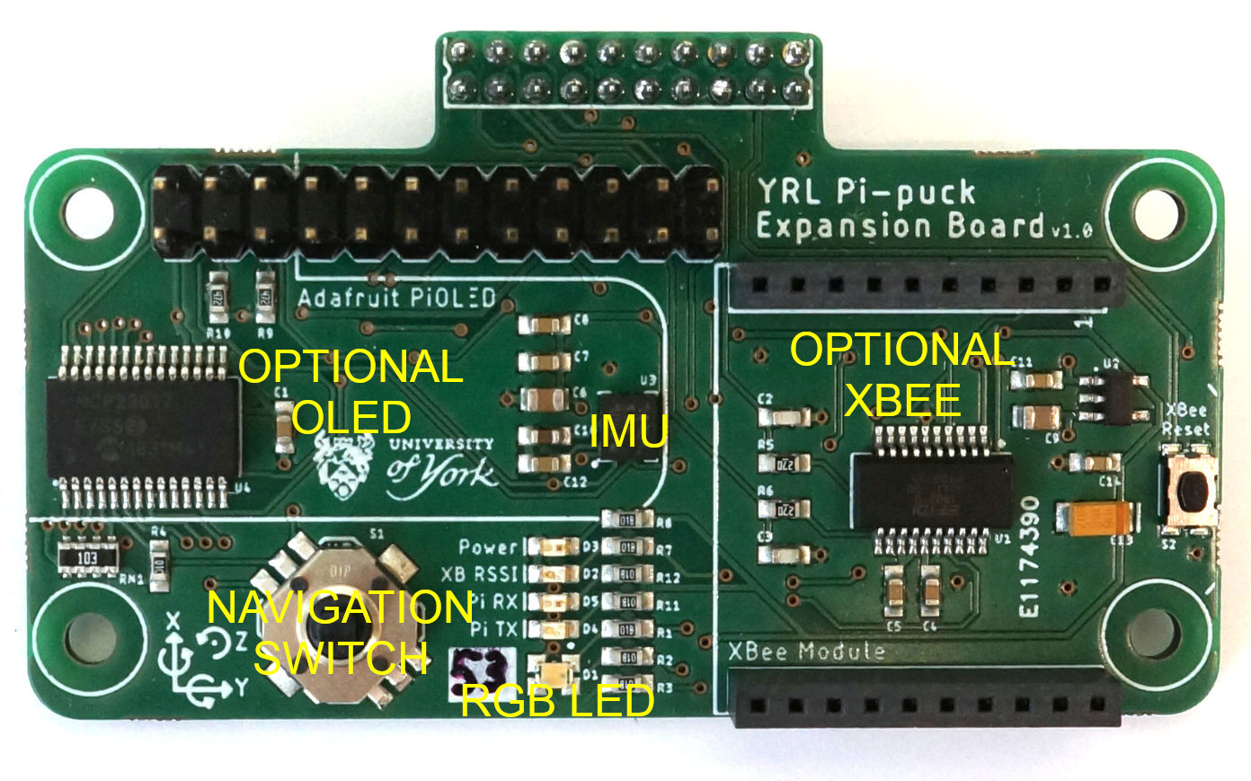
= | =York Robotics Lab Expansion Board= | ||
The York Robotics Lab developed an expansion board for the Pi-puck extension that includes: 9-DoF IMU, 5-input navigation switch, RGB LED, XBee socket, 24-pin Raspberry Pi compatible header. For more information have a look at [https://pi-puck.readthedocs.io/en/latest/extensions/yrl-expansion/ https://pi-puck.readthedocs.io/en/latest/extensions/yrl-expansion/].<br/> | |||
<span class="plainlinks">[https://projects.gctronic.com/epuck2/wiki_images/yrl-expansion-top.jpg <img width=350 src="https://projects.gctronic.com/epuck2/wiki_images/yrl-expansion-top.jpg">]</span><br/> | |||
An example showing how to communicate with the YRL expansion board is available in the Pi-puck repository of the York Robotics Lab: | |||
# <code> git clone https://github.com/yorkrobotlab/pi-puck.git pi-puck_yrl</code> | |||
# <code>cd pi-puck_yrl/python-library</code> | |||
# <code>python3 pipuck-library-test.py -x</code> Once started, press in sequence up, down, left, right, center to continue the demo. | |||
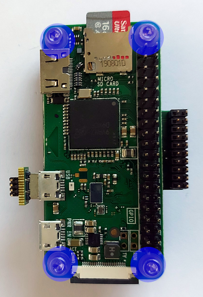
= | ==Assembly== | ||
The assembly is very simple: place the YRL expansion board on top of the Raspberry Pi and then connect them with the provided screws. Once they are connected, you can attach both on top of the Pi-puck extension.<br/> | |||
<span class="plainlinks">[https:// | <span class="plainlinks">[https://projects.gctronic.com/epuck2/wiki_images/yrl-exp1.jpg <img width=200 src="https://projects.gctronic.com/epuck2/wiki_images/yrl-exp1.jpg">]</span> | ||
<span class="plainlinks">[https://projects.gctronic.com/epuck2/wiki_images/yrl-exp2.jpg <img width=150 src="https://projects.gctronic.com/epuck2/wiki_images/yrl-exp2.jpg">]</span> | |||
<span class="plainlinks">[https://projects.gctronic.com/epuck2/wiki_images/yrl-exp3.jpg <img width=200 src="https://projects.gctronic.com/epuck2/wiki_images/yrl-exp3.jpg">]</span><br/> | |||
==XBee== | |||
In this section it is explained how to send data from the Pi-puck to the computer using XBee modules Series 1. | |||
The XBee module mounted on the YRL expansion must be programmed with the <code>XBEE 802.15.4-USB ADAPTER</code> firmware; this can be done with the [http://www.digi.com/products/wireless-wired-embedded-solutions/zigbee-rf-modules/xctu XTCU software]. With XTCU be sure to program also the same parameters on both modules in order to be able to communicate between each other: <code>Channel</code> (e.g. <code>C</code>), <code>PAN ID</code> (e.g. <code>3332</code>), <code>DH = 0</code>, <code>DL = 0</code>, <code>MY = 0</code>. | |||
: | |||
Some Python examples ara available in the [https://github.com/yorkrobotlab/pi-puck-expansion-board YRL Expansion Board GitHub repository] that can be used to communicate with the XBee module mounted on the YRL expansion. These examples are based on the [https://github.com/digidotcom/xbee-python Digi XBee Python library] that can be installed with the command <code>pip3 install digi-xbee</code>. This library requires the XBee module to be configured in API mode; you can setup this mode following these steps: | |||
# <code> git clone https://github.com/yorkrobotlab/pi-puck-expansion-board.git</code> | |||
# <code>cd pi-puck-expansion-board/xbee</code> | |||
# <code>python3 xbee-enable-api-mode.py</code> | |||
Now connect the second module to the computer and run XTCU, select the console view and open the serial connection. Then run the [https://projects.gctronic.com/epuck2/PiPuck/xbee-send-broadcast.py xbee-send-broadcast.py] example from the Pi-puck by issuing the command: <code>python3 xbee-send-broadcast.py</code>. From the XTCU console you should receive <code>Hello Xbee World!</code>. | |||
For more information refer to [https://pi-puck.readthedocs.io/en/latest/extensions/yrl-expansion/xbee/ https://pi-puck.readthedocs.io/en/latest/extensions/yrl-expansion/xbee/]. | |||
=Time-of-Flight Distance Sensor add-on= | |||
The Pi-puck extension integrates six sensor board sockets that can be used to add up to six VL53L1X-based distance sensor add-ons. The Pi-puck equipped with these add-ons is shown in the following figure:<br/> | |||
<span class="plainlinks">[https://projects.gctronic.com/epuck2/wiki_images/pi-puck-tof.jpg <img width=250 src="https://projects.gctronic.com/epuck2/wiki_images/pi-puck-tof.jpg">]</span><br/> | |||
For more information have a look at [https://pi-puck.readthedocs.io/en/latest/extensions/tof-sensor/#time-of-flight-distance-sensor https://pi-puck.readthedocs.io/en/latest/extensions/tof-sensor/#time-of-flight-distance-sensor]. | |||
= | <font style="color:red"> Beware that once the socket for the ToF add-on sensor '''3''' is soldered on the pi-puck extension, you are no more able to connect the HDMI cable.</font> | ||
==Communicate with the ToF sensors== | |||
In order to communicate with the sensors you can use the <code>multiple-i2c-bus-support</code> branch of the [https://github.com/pimoroni/vl53l1x-python vl53l1x-python] library from [https://shop.pimoroni.com/ Pimoroni]. To install this library follow these steps: | |||
# <code>git clone -b multiple-i2c-bus-support https://github.com/pimoroni/vl53l1x-python.git</code> | |||
# <code>cd vl53l1x-python</code> | |||
# <code>sudo python3 setup.py install</code> | |||
A Python example showing how to read data from the ToF sensors is available in the Pi-puck repository of the York Robotics Lab: | |||
# <code> git clone https://github.com/yorkrobotlab/pi-puck.git pi-puck_yrl</code> | |||
# <code>cd pi-puck_yrl/python-library</code> | |||
# <code>python3 pipuck-library-test.py -t</code> | |||
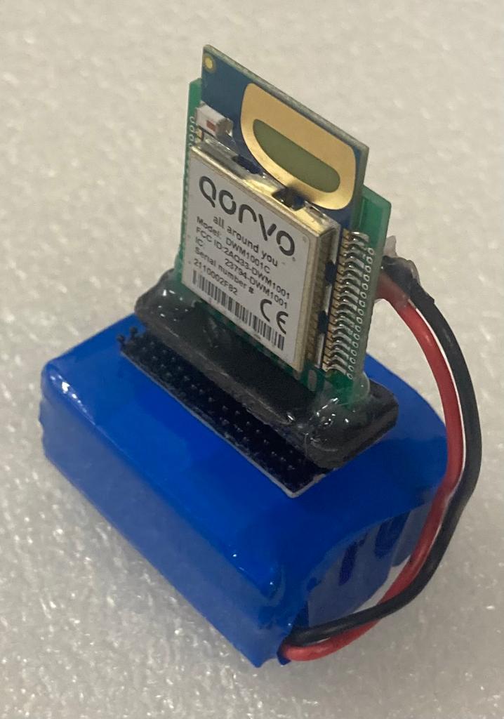
== | =Ultra Wide Band extension for Pi-Puck= | ||
<span class="plainlinks">[https://projects.gctronic.com/epuck2/wiki_images/uwb-top.jpg <img width=200 src="https://projects.gctronic.com/epuck2/wiki_images/uwb-top.jpg">]</span> | |||
<span class="plainlinks">[https://projects.gctronic.com/epuck2/wiki_images/uwb-front.jpg <img width=200 src="https://projects.gctronic.com/epuck2/wiki_images/uwb-front.jpg">]</span><br/> | |||
The | The Ultra Wide Band extension is connected to the Pi-Puck extension through the extension connector pins (2x10). The SPI channel is used for the communication between the Raspberry Pi and the Ultra Wide Band module so that the user is able to configure the module and receive position information from the RPi OS. Here are some examples:<br/> | ||
* Anchor configuration: [https://projects.gctronic.com/epuck2/uwb/conf_anchor.zip conf_anchor.zip] | |||
* Tag configuration: [https://projects.gctronic.com/epuck2/uwb/conf_tag.zip conf_tag.zip] | |||
* Get position from tag: [https://projects.gctronic.com/epuck2/uwb/tag_get_pos.zip tag_get_pos.zip] | |||
In order to build the examples the following software package [https://projects.gctronic.com/epuck2/uwb/DWM1001_DWM1001-DEV_MDEK1001_Sources_and_Docs_v11.zip DWM1001_DWM1001-DEV_MDEK1001_Sources_and_Docs_v11.zip] need to be downloaded and transferred to the pi-puck system: the examples need to be extracted inside the <code>DWM1001_DWM1001-DEV_MDEK1001_Sources_and_Docs_v11\DWM1001\Source_Code\DWM1001_host_api\dwm1001_host_api\examples</code> directory, then simply issue the <code>make</code> command to build. | |||
The | The following Android application [https://projects.gctronic.com/epuck2/uwb/DRTLS_Manager_R2.apk DRTLS_Manager_R2.apk] can also be used to configure the Ultra Wide Band extension.<br/> | ||
To get started you need 4 <code>ANCHORS</code> to delimit your arena (see following figure); they are standalone and the Ultra Wide Band extension is equipped with a standard battery connector for easy recharging.<br/> | |||
<span class="plainlinks">[https://projects.gctronic.com/epuck2/wiki_images/uwb-anchor-front.jpeg <img width=200 src="https://projects.gctronic.com/epuck2/wiki_images/uwb-anchor-front.jpeg">]</span><br/> | |||
Then you can equip your robots with the Ultra Wide Band extension and by configuring them as <code>TAG</code> you will receive their position inside the arena. <br/> | |||
< | |||
</ | |||
< | |||
< | |||
</ | |||
During our test on a 2m x 2m arena with 4 anchors we get position (x, y) accuracy of the e-puck2 robot of about 7cm. Have a look at the following video: | |||
{{#ev:youtube|RpJ8NqjytHM}} | |||
And also with 4 tags: | |||
{{#ev:youtube|rFIyvbyULj4}} | |||
= | ==Documentation== | ||
# [https://projects.gctronic.com/epuck2/uwb/DWM1001C_Datasheet.pdf DWM1001C_Datasheet.pdf] | |||
# [https://projects.gctronic.com/epuck2/uwb/DWM1001-Firmware-User-Guide.pdf DWM1001-Firmware-User-Guide.pdf] | |||
# [https://projects.gctronic.com/epuck2/uwb/DWM1001-API-Guide.pdf DWM1001-API-Guide.pdf] | |||
Latest revision as of 14:14, 6 March 2024
Hardware
Overview
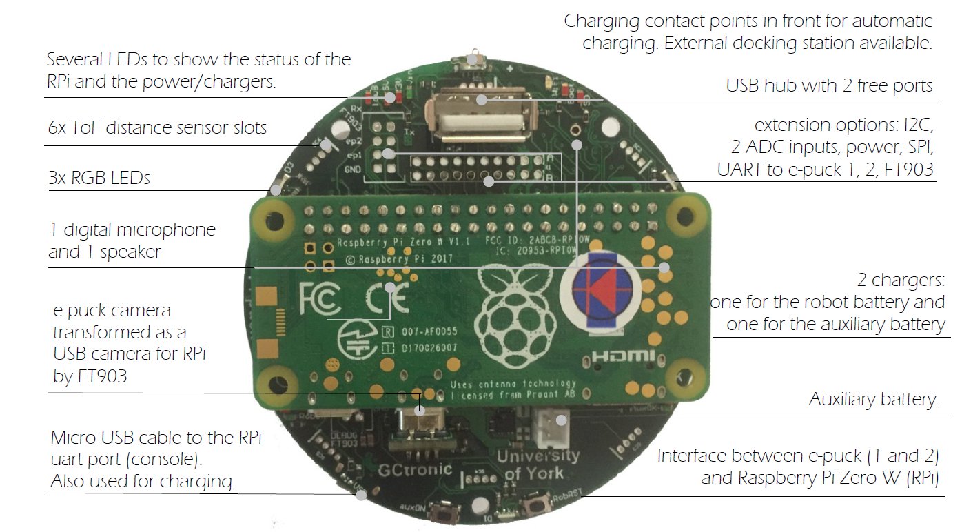
Features:
- Raspberry Pi Zero W or Zero 2 W connected to the robot via I2C
- interface between the robot base camera and the rPi via USB, up to 15 FPS
- 1 digital microphone and 1 speaker
- USB hub connected to the rPi with 2 free ports
- uUSB cable to the rPi uart port. Also ok for charging
- 2 chargers. 1 for the robot battery and 1 for the auxiliary battery on top of the extension
- charging contact points in front for automatic charging. External docking station available
- several extension options. 6 i2C channels, 2 ADC inputs
- several LED to show the status of the rPi and the power/chargers
I2C bus
I2C is used to let communicate various elements present in the robot, Pi-puck and extensions. An overall schema is shown in the following figure:

An I2C switcher is included in the Pi-puck extension in order to support additional I2C buses (the RPi alone has only one usable I2C bus). These are needed to avoid conflicts between Time-of-Flight sensors that have a fixed I2C address.
Getting started
This introductory section explains the minimal procedures needed to work with the Raspberry Pi Zero W / Zero 2 W mounted on the Pi-puck extension board and gives a general overview of the available basic demos and scripts shipped with the system flashed on the micro SD. More advanced demos are described in the following separate sections (e.g. ROS), but the steps documented here are fundamental, so be sure to fully understand them.
The extension is mostly an interface between the e-puck robot and the Raspberry Pi, so you can exploit the computational power of a Linux machine to extend the robot capabilities.
In most cases, the Pi-puck extension will be attached to the robot, but it's interesting to note that it can be used also alone when the interaction with the robot isn't required.
The following sections assume the full configuration (robot + extension), unless otherwise stated.
Requirements
The robot must be programmed with a special firmware in order to communicate via I2C bus with the Raspberry Pi mounted on the Pi-puck extension. The same I2C bus is shared by all the devices (camera, IMU, distance sensor, others extensions), the main microcontroller and the Raspberry Pi. Since the Raspberry Pi acts as I2C master, these devices will not be anymore reachable directly from the robot main microcontroller that will act instead as I2C slave.
e-puck version 1
The e-puck version 1 robot must be programmed with the following firmware pi-puck-e-puck1.hex.
e-puck version 2
The e-puck version 2 robot must be programmed with the following firmware e-puck2_main-processor_extension.elf (07.06.19) and the selector must be placed in position 10(A).
The source code is available in the gumstix branch of the repo https://github.com/e-puck2/e-puck2_main-processor.
Turn on/off the extension
To turn on the extension you need to press the auxON button as shown in the follwoing figure; this will turn on also the robot (if not already turned on). Similarly, if you turn on the robot then also the extension will turn on automatically.
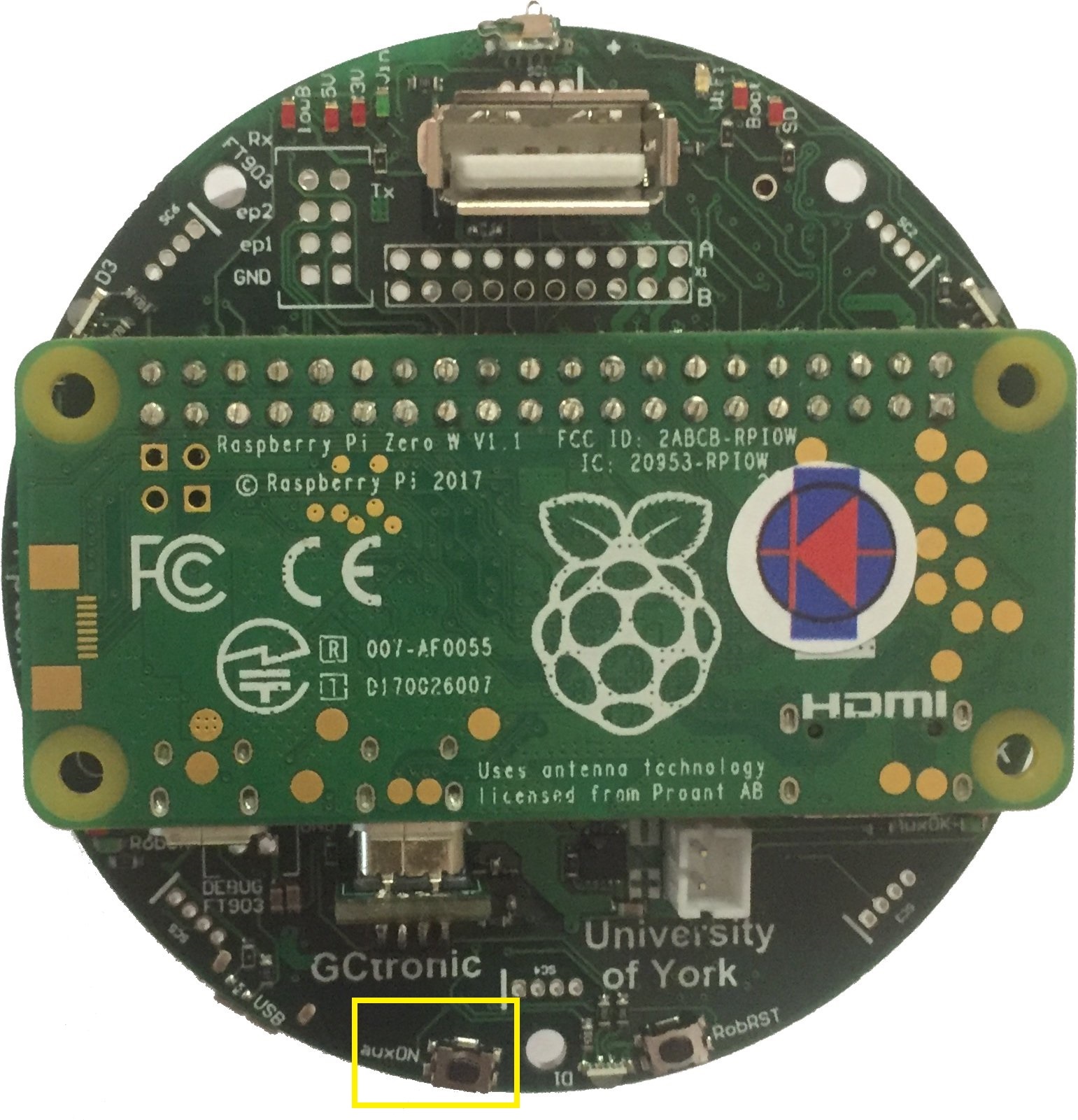
To turn off the Pi-puck you need to press and hold the auxON button for 2 seconds; this will initiate the power down procedure.
Beware that by turning off the robot, the extension will not be turned off automatically if it is powered from another source like the micro usb cable or a secondary battery. You need to use its power off button to switch it off. Instead if there is no other power source, then by turning off the robot also the extension will be turned off (not cleanly).
Console mode
The Pi-puck extension board comes with a pre-configured system ready to run without any additional configuration.
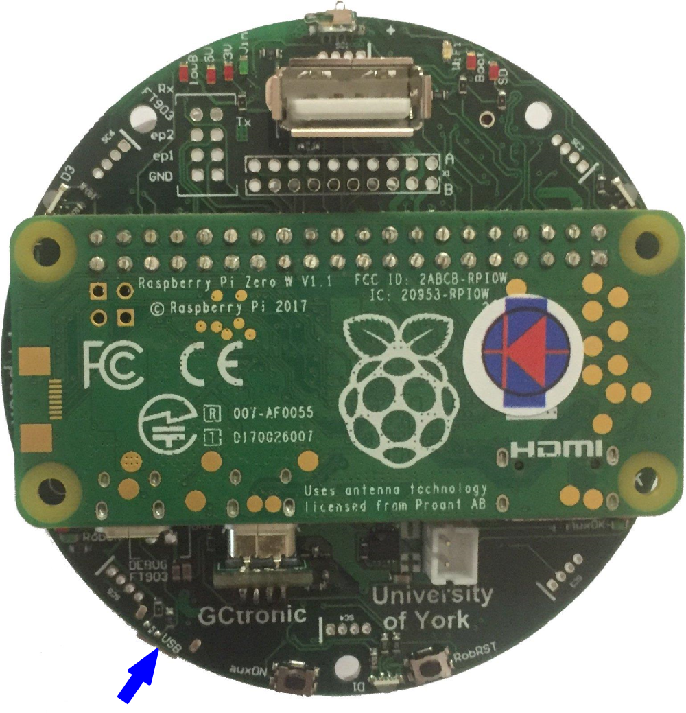
In order to access the system from a PC in console mode, the following steps must be performed:
1. connect a micro USB cable from the PC to the extension module. If needed, the drivers are available in the following link USB to UART bridge drivers
2. execute a terminal program and configure the connection with 115200-8N1 (baudrate, 8 bits, no flow control). The serial device is the one created when the extension is connected to the computer
3. switch on the robot (the extension will turn on automatically); now the terminal should display the Raspberry Pi booting information. If the robot isn't present, then you can directly power on the extension board with the related button
4. login with user = pi, password = raspberry
Battery charge
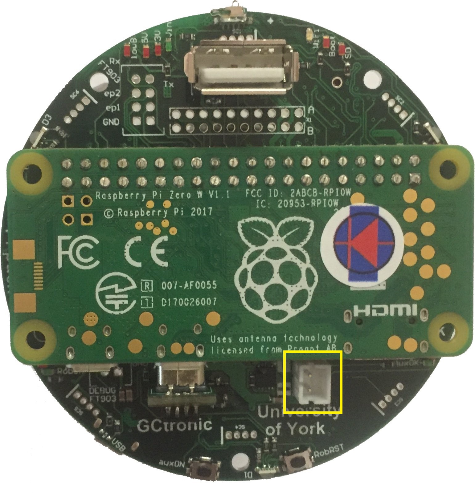
You can either charge the robot battery or the additional battery connected to the Pi-puck extension or both the batteries by simply plugging the micro USB cable.
The following figure shows the connector for the additional battery.
The robot can also autonomously charge itself if the charging wall is available. The Pi-puck extension includes two spring contacts on the front side that let the robot easily make contact with the charging wall and charge itself. The charging wall and the spring contacts are shown in the following figures:
Reset button
A button is available to reset the robot, when pressed it will resets only the robot restarting its firmware. This is useful for instance during development or for specific demos in which a restart of the robot is needed. In these cases you don't need to turn off completely the robot (and consequently also the Pi-puck if energy is supplied by the robot) but instead you can simply reset the robot. The position of the reset button is shown in the following figure:
How to communicate with the robot and its sensors
Communicate with the e-puck version 1
Refer to the repo https://github.com/yorkrobotlab/pi-puck-e-puck1.
Communicate with the e-puck version 2
An example showing how to exchange data between the robot and the Pi-puck extension is available in the Pi-puck repository; you can find it in the directory /home/pi/Pi-puck/e-puck2/.
You can build the program with the command gcc e-puck2_test.c -o e-puck2_test.
Now you can run the program by issueing ./e-puck2_test; this demo will print the sensors data on the terminal and send some commands to the robot at 2 Hz.
The same example is also available in Python, you can run it by issueing python3 e-puck2_test.py.
Packet format
Extension to robot packet format, 20 bytes payload (the number in the parenthesis represents the bytes for each field):
| Left speed (2) | Right speed (2) | Speaker (1) | LED1, LED3, LED5, LED7 (1) | LED2 RGB (3) | LED4 RGB (3) | LED6 RGB (3) | LED8 RGB (3) | Settings (1) | Checksum (1) |
- Left, right speed: [-2000 ... 2000]
- Speaker: sound id = [0, 1, 2]
- LEDs on/off flag: bit0 for LED1, bit1 for LED3, bit2 for LED5, bit3 for LED7
- RGB LEDs: [0 (off) ... 100 (max)]
- Settings:
- bit0: 1=calibrate IR proximity sensors
- bit1: 0=disable onboard obstacle avoidance; 1=enable onboard obstacle avoidance (not implemented yet)
- bit2: 0=set motors speed; 1=set motors steps (position)
- Checksum: Longitudinal Redundancy Check (XOR of the bytes 0..18)
Robot to extension packet format, 47 bytes payload (the number in the parenthesis represents the bytes for each field):
| 8 x Prox (16) | 8 x Ambient (16) | 4 x Mic (8) | Selector + button (1) | Left steps (2) | Right steps (2) | TV remote (1) | Checksum |
- Selector + button: selector values represented by 4 least significant bits (bit0, bit1, bit2, bit3); button state is in bit4 (1=pressed, 0=not pressed)
- Checksum: Longitudinal Redundancy Check (XOR of the bytes 0..45)
Communicate with the IMU
e-puck version 1
An example written in C showing how to read data from the IMU (LSM330) mounted on e-puck version 1.3 is available in the Pi-puck repository; you can find it in the directory /home/pi/Pi-puck/e-puck1/.
You can build the program with the command gcc e-puck1_imu.c -o e-puck1_imu.
Now you can run the program by issueing ./e-puck1_imu and then choose whether to get data from the accelerometer or gyroscope; this demo will print the sensors data on the terminal.
e-puck version 2
An example showing how to read data from the IMU (MPU-9250) is available in the Pi-puck repository; you can find it in the directory /home/pi/Pi-puck/e-puck2/.
You can build the program with the command gcc e-puck2_imu.c -o e-puck2_imu.
Now you can run the program by issueing ./e-puck2_imu and then choose whether to get data from the accelerometer or gyroscope; this demo will print the sensors data on the terminal.
The same example is also available in Python, you can run it by issueing python3 e-puck2_imu.py.
Communicate with the ToF sensor
The Time of Flight sensor is available only on the e-puck version 2 robot.
First of all you need to verify that the VL53L0X Python package is installed with the following command: python3 -c "import VL53L0X". If the command returns nothing you're ready to go, otherwise if you receive an ImportError then you need to install the package with the command: pip3 install git+https://github.com/gctronic/VL53L0X_rasp_python.
A Python example showing how to read data from the ToF sensor is available in the Pi-puck repository; you can find it in the directory /home/pi/Pi-puck/e-puck2/.
You can run the example by issueing python3 VL53L0X_example.py (this is the example that you can find in the repository https://github.com/gctronic/VL53L0X_rasp_python/tree/master/python).
Capture an image
The robot camera is connected to the Pi-puck extension as a USB camera, so you can access it very easily.
An example showing how to capture an image from the robot's camera using OpenCV is available in the Pi-puck repository; you can find it in the directory /home/pi/Pi-puck/snapshot/.
You can build the program with the command g++ $(pkg-config --libs --cflags opencv) -ljpeg -o snapshot snapshot.cpp.
Now you can run the program by issueing ./snapshot; this will save a VGA image (JPEG) named image01.jpg to disk.
The program can accept the following parameters:
-d DEVICE_ID to specify the input video device from which to capture an image, by default is 0 (/dev/video0). This is useful when working also with the Omnivision V3 extension that crates another video device; in this case you need to specify -d 1 to capture from the robot camera.
-n NUM to specify how many images to capture (1-99), by default is 1
-v to enable verbose mode (print some debug information)
Beware that in this demo the acquisition rate is fixed to 5 Hz, but the camera supports up to 15 FPS.
The same example is also available in Python, you can run it by issueing python snapshot.py.
Communicate with the ground sensors extension
Both e-puck version 1 and e-puck version 2 support the ground sensors extension.
This extension is attached to the I2C bus and can be read directly from the Pi-puck.
An example written in C showing how to read data from the ground sensors extension is available in the Pi-puck repository; you can find it in the directory /home/pi/Pi-puck/ground-sensor/.
You can build the program with the command gcc groundsensor.c -o groundsensor.
Now you can run the program by issueing ./groundsensor; this demo will print the sensors data on the terminal.
The same example is also available in Python, you can run it by issueing python3 groundsensor.py.
Communicate with the range and bearing extension
Both e-puck version 1 and e-puck version 2 support the range and bearing extension.
This extension is attached to the I2C bus and can be read directly from the Pi-puck.
An example written in C showing how to start playing with the range and bearing extension is available in the Pi-puck repository; you can find it in the directory /home/pi/Pi-puck/randb/. You need two boards: one is the transmitter (run randb_tx) and the other is the receiver (run randb_rx). The receiver will print the data received from the transmitter.
You can build the programs with the command gcc randb_tx.c -o randb_tx and gcc randb_rx.c -o randb_rx.
The same example is also available in Python, you can run it by issueing python3 randb_tx.py and python3 randb_rx.py.
For best performances you need also to take in consideration the interference given by the time of flight and proximity sensors (see https://www.gctronic.com/doc/index.php?title=Others_Extensions#e-puck_2).
Wireless remote control
If you want to control the robot from a computer, for instance when you have an algorithm that requires heavy processing not suitable for the Pi-puck or when the computer acts as a master controlling a fleet of robots that return some information to the controller, then you have 3 options:
1) The computer establishes a WiFi connection with the Pi-puck to receive data processed by the Pi-puck (e.g. results of an image processing task); at the same time the computer establishes a Bluetooth connection directly with the e-puck version 2 robot to control it.
- Disadvantages:
- - the Bluetooth standard only allow up to seven simultaneous connections
- - doubled latency (Pi-puck <-> pc and pc <-> robot)
2) The computer establishes a WiFi connection with both the Pi-puck and the e-puck version 2 robot.
- Advantages:
- - only one connection type needed, easier to handle
- Disadvantages:
- - doubled latency (Pi-puck <-> pc and pc <-> robot)
3) The computer establishes a WiFi connection with the Pi-puck and then the Pi-puck is in charge of controlling the robot via I2C based on the data received from the computer controller.
- Advantages:
- - less latency involved
- - less number of connections to handle
- - depending on your algorithm, it would be possible to initially develop the controller on the computer (easier to develop and debug) and then transfer the controller directly to the Pi-puck without the need to change anything related to the control of the robot via I2C
The following figure summarizes these 3 options:
How to work with the Pi-puck
Demos and scripts update
First of all you should update to the last version of the demos and scripts released with the system that you can use to start playing with the Pi-puck extension and the robot.
To update the repository follow these steps:
1. go to the directory /home/pi/Pi-puck
2. issue the command git pull
Then to update some configurations of the system:
1. go to the directory /home/pi/Pi-puck/system
2. issue the command ./update.sh; the system will reboot.
You can find the Pi-puck repository here https://github.com/gctronic/Pi-puck.
Audio recording
Use the arecord utility to record audio from the onboard microphone. The following example shows how to record an audio of 2 seconds (-d parameter) and save it to a wav file (test.wav):
arecord -Dmic_mono -c1 -r16000 -fS32_LE -twav -d2 test.wav
You can also specify a rate of 48 KHz with -r48000
Audio play
Use aplay to play wav files and mplayer to play mp3 files.
Battery reading
A Python example showing how to measure both the battery of the robot and the battery of the Pi-puck extension is available in the Pi-puck repository; you can find it in the directory /home/pi/Pi-puck/battery/.
You can start reading the batteries values by issueing python read-battery.py.; this demo will print the batteries values (given in Volts) on the terminal.
An additional Python example is provided in the same directory showing how to detect when the robot is in charge: this is a basic demo in which the robot goes forward and stop only when it is in charge, it can be used as a starting point for more advanced examples. To run this demo issue the commands sudo pigpiod and then python3 goto-charge.py.
WiFi configuration
Specify your network configuration in the file /etc/wpa_supplicant/wpa_supplicant-wlan0.conf.
Example:
ctrl_interface=DIR=/var/run/wpa_supplicant GROUP=netdev
update_config=1
country=CH
network={
        ssid="MySSID"
        psk="9h74as3xWfjd"
}
You can have more than one network parameter to support more networks. For more information about wpa_supplicant refer to https://hostap.epitest.fi/wpa_supplicant/.
Once the configuration is done, you can also connect to the Pi-puck with SSH. If you are working in Windows you can use PuTTY.
How to know your IP address
A simple method to know your IP address is to connect the USB cable to the Pi-puck extension and issue the command ip a; from the command's result you will be able to get you current assigned IP address.
If you prefer to know your IP address remotely (without connecting any cable) then you can use nmap.
For example you can search all connected devices in your network with the following command: nmap 192.168.1.*. Beware that you need to specify the subnet based on your network configuration.
From the command's result you need to look for the hostname raspberrypi.
If you are working in Windows you can use the Zenmap application.
File transfer
USB cable
You can transfer files via USB cable between the computer and the Pi-puck extension by using on of the zmodem protocol.
The lrzsz package is pre-installed in the system, thus you can use the sx and rx utilities to respectevely send files to the computer and receive files from the computer.
Example of sending a file to the computer using the Minicom terminal program:
1. in the Pi-puck console type sx --zmodem fliename.ext. The transfer should start automatically and you'll find the file in the home directory.
Example of receiving a file from the computer using the Minicom terminal program:
1. in the Pi-puck console type rx -Z
2. to start the transfer type the sequence CTRL+A+S, then chose zmodem and select the file you want to send with the spacebar. Finally press enter to start the transfer.
WiFi
The Pi-puck extension supports SSH connections.
To exchange files between the Pi-puck and the computer, the scp tool (secure copy) can be used. An example of transferring a file from the Pi-puck to the computer is the following:
scp pi@192.168.1.20:/home/pi/example.txt example.txt
If you are working in Windows you can use PuTTY.
Image streaming
Bluetooth LE
An example of a BLE uart service is available in the Pi-puck repository; you can find it in the directory /home/pi/Pi-puck/ble/.
To start the service you need to type: python uart_peripheral.py.
Then you can use the e-puck2-android-ble app you can find in chapter Connecting to the BLE in order to connect to the Pi-puck extension via BLE. Once connected you'll receive some dummy data for the proximity values and by clicking on the motion buttons you'll see the related action printed on the Pi-puck side. This is a starting point that you can extend based on your needs.
Operating system
The system is based on Raspbian Stretch and can be downloaded from the following link pi-puck-os_25.05.22.zip.
When booting the first time, the first thing to do is expanding the file system in order to use all the available space on the micro sd:
1. sudo raspi-config
2. Select Advanced Options and then Expand Filesystem
3. reboot
e-puck version 2 camera configuration
The e-puck version 2 camera need to be configured through I2C before it can be used. For this reason a Python script is called at boot that detects and configures the camera. The script resides in the Pi-puck repository installed in the system (/home/pi/Pi-puck/camera-configuration.py), so beware to not remove it.
If the robot is plugged after the boot process is completed, you need to call manually the Python configuration script before using the camera by issueing the command python3 /home/pi/Pi-puck/camera-configuration.py.
In order to automatically run the script at boot, the /etc/rc.local was modified by adding the call to the script just before the end of the file.
Power button handling
The power button press is handled by a background service (systemd) started automatically at boot. The service description file is located in /etc/systemd/system/power_handling.service and it calls the /home/pi/power-handling/ program. Beware to not remove neither of these files.
The source code of the power button handling program is available in the Pi-puck repository and is located in /home/pi/Pi-puck/power-handling/power-handling.c.
Desktop mode
The system starts in console mode, to switch to desktop (LXDE) mode issue the command startx.
Camera viewer
A camera viewer called luvcview is installed in the system. You can open a terminal and issue simply the command luvcview to see the image coming from the robot camera.
VNC
VNC is a remote control desktop application that lets you connect to the Pi-puck from your computer and then you will see the desktop of the Pi-puck inside a window on your computer. You'll be able to control it as though you were working on the Pi-puck itself.
VNC is installed in the system and the VNC server is automatically started at boot, thus you can connect with VNC Viewer from your computer by knowing the IP address of the Pi-puck (refer to section How to know your IP address).
Notice that the VNC server is started also in console mode.
I2C communication
The communication between the Pi-puck extension and the robot is based on I2C. The system is configured to exploit the I2C hardware peripheral in order to save CPU usage, but if you need to use the software I2C you can enable it by modifying the /boot/config.txt file and removing the # symbol (comment) in front of the line with the text dtparam=soft_i2c (it is placed towards the end of the file).
Audio output configuration
You can enable or disable audio output by modifying the config.txt file in the boot partition.
To enable audio output insert the line: gpio=22=op,dh
To disable audio output insert the line: gpio=22=op,dl
If you don't need to play audio files it is suggested to disable audio output in order to save power.
ROS
ROS Kinetic is integrated in the Pi-puck system.
A ROS node developed to run in the Pi-puck is available for both CPP and Python, the communication system is based on the third architecture shown in chapter Wireless remote control; a more detailed schema is shown below:
Initial configuration
The ROS workspace is located in ~/rosbots_catkin_ws/
The e-puck version 2 ROS driver is located in ~/rosbots_catkin_ws/src/epuck_driver_cpp/
Remember to follow the steps in the section Requirements and section Demos and scripts update, only once.
The PC (if used) and the Pi-puck extension are supposed to be configured in the same network.
Running roscore
roscore can be launched either from the PC or directly from the Pi-puck.
Before starting roscore, open a terminal and issue the following commands:
export ROS_IP=roscore-ipexport ROS_MASTER_URI=http://roscore-ip:11311
where roscore-ip is the IP of the machine that runs roscore
Then start roscore by issueing roscore.
Running the ROS node
Before starting the e-puck version 2 ROS node on the Pi-puck, issue the following commands:
export ROS_IP=pipuck-ipexport ROS_MASTER_URI=http://roscore-ip:11311
where pipuck-ip is the IP of the Pi-puck extension and roscore-ip is the IP of the machine that runs roscore (can be the same IP if roscore runs directly on the Pi-puck).
To start the e-puck version 2 ROS node issue the command:
roslaunch epuck_driver_cpp epuck_minimal.launch debug_en:=true ros_rate:=20
The following graph shows all the topics published by the e-puck version 2 driver node:
 Click to enlarge
Test the communication
You can test if the communication between the robot and the computer is actually working by simply display messages published by a topic, e.g.:
rostopic echo /proximity0
You can have the list of all the topics by issuing the command: rostopic list.
You can move the robot straight forward by issuing rostopic pub -1 /mobile_base/cmd_vel geometry_msgs/Twist -- '[4.0, 0.0, 0.0]' '[0.0, 0.0, 0.0]'.
You can rotate the robot on the spot by issuing rostopic pub -1 /mobile_base/cmd_vel geometry_msgs/Twist -- '[0.0, 0.0, 0.0]' '[0.0, 0.0, 1.0]'.
You can change the LEDs state by issuing rostopic pub -1 /mobile_base/cmd_led std_msgs/UInt8MultiArray "{data: [LED1, LED3, LED5, LED7]}", e.g. rostopic pub -1 /mobile_base/cmd_led std_msgs/UInt8MultiArray "{data: [1, 1, 1, 1]}" to turn them all on.
Get the source code
The last version of the e-puck version 2 ROS node can be downloaded from the git: git clone -b pi-puck https://github.com/gctronic/epuck_driver_cpp.git
To update to the last version follow these steps:
cd ~/rosbots_catkin_ws/src/rm -R -f epuck_driver_cppgit clone -b pi-puck https://github.com/gctronic/epuck_driver_cpp.gitcd ~/rosbots_catkin_ws/catkin_make --only-pkg-with-deps epuck_driver_cpp
Python version
A Python version developed by the York University can be found here https://github.com/yorkrobotlab/pi-puck-ros.
ROS 2
ROS2 Foxy running on Raspberry Pi OS Buster is available in the following link ros2_foxy_epuck2.img.
Running ROS 2 node
To start the robot node issue the command ros2 run epuck_ros2_driver driver.
To start the camera node issue the command ros2 run epuck_ros2_camera camera.
Test the communication
You can test if the communication between the robot and the computer is actually working by simply display messages published by a topic, e.g.:
ros2 topic echo /tof
You can have the list of all the topics by issuing the command: ros2 topic list.
You can move the robot straight forward by issuing ros2 topic pub -1 /cmd_vel geometry_msgs/Twist "{linear:{x: 2.0, y: 0.0, z: 0.0}, angular:{x: 0.0, y: 0.0, z: 0.0}}".
You can change the LEDs state by issuing ros2 topic pub -1 /led0 std_msgs/msg/Bool "{data: true}".
Get the source code
The last version of the e-puck version 2 ROS 2 node can be downloaded from the git: git clone https://github.com/cyberbotics/epuck_ros2.git
OpenCV
OpenCV 3.4.1 is integrated in the Pi-puck system.
York Robotics Lab Expansion Board
The York Robotics Lab developed an expansion board for the Pi-puck extension that includes: 9-DoF IMU, 5-input navigation switch, RGB LED, XBee socket, 24-pin Raspberry Pi compatible header. For more information have a look at https://pi-puck.readthedocs.io/en/latest/extensions/yrl-expansion/.
An example showing how to communicate with the YRL expansion board is available in the Pi-puck repository of the York Robotics Lab:
git clone https://github.com/yorkrobotlab/pi-puck.git pi-puck_yrlcd pi-puck_yrl/python-librarypython3 pipuck-library-test.py -xOnce started, press in sequence up, down, left, right, center to continue the demo.
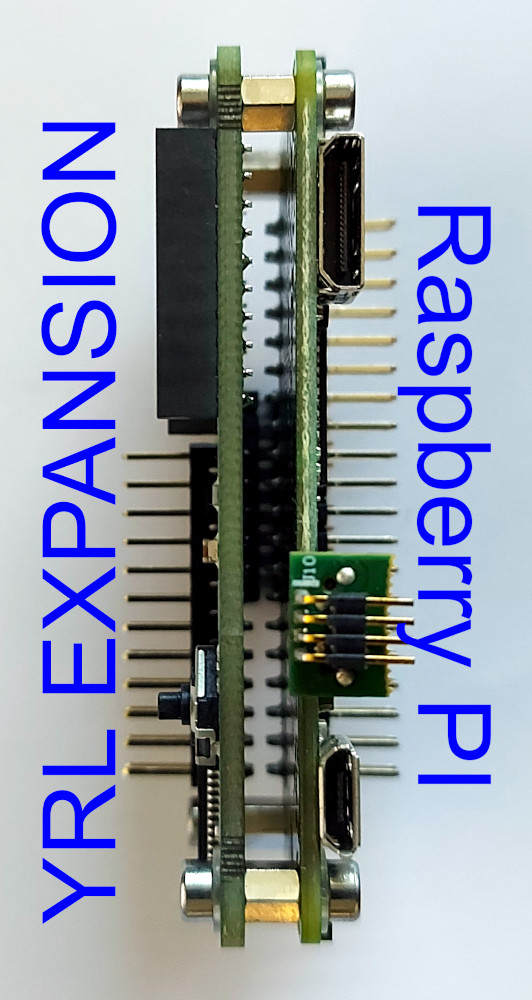
Assembly
The assembly is very simple: place the YRL expansion board on top of the Raspberry Pi and then connect them with the provided screws. Once they are connected, you can attach both on top of the Pi-puck extension.

XBee
In this section it is explained how to send data from the Pi-puck to the computer using XBee modules Series 1.
The XBee module mounted on the YRL expansion must be programmed with the XBEE 802.15.4-USB ADAPTER firmware; this can be done with the XTCU software. With XTCU be sure to program also the same parameters on both modules in order to be able to communicate between each other: Channel (e.g. C), PAN ID (e.g. 3332), DH = 0, DL = 0, MY = 0.
Some Python examples ara available in the YRL Expansion Board GitHub repository that can be used to communicate with the XBee module mounted on the YRL expansion. These examples are based on the Digi XBee Python library that can be installed with the command pip3 install digi-xbee. This library requires the XBee module to be configured in API mode; you can setup this mode following these steps:
git clone https://github.com/yorkrobotlab/pi-puck-expansion-board.gitcd pi-puck-expansion-board/xbeepython3 xbee-enable-api-mode.py
Now connect the second module to the computer and run XTCU, select the console view and open the serial connection. Then run the xbee-send-broadcast.py example from the Pi-puck by issuing the command: python3 xbee-send-broadcast.py. From the XTCU console you should receive Hello Xbee World!.
For more information refer to https://pi-puck.readthedocs.io/en/latest/extensions/yrl-expansion/xbee/.
Time-of-Flight Distance Sensor add-on
The Pi-puck extension integrates six sensor board sockets that can be used to add up to six VL53L1X-based distance sensor add-ons. The Pi-puck equipped with these add-ons is shown in the following figure:
For more information have a look at https://pi-puck.readthedocs.io/en/latest/extensions/tof-sensor/#time-of-flight-distance-sensor.
Beware that once the socket for the ToF add-on sensor 3 is soldered on the pi-puck extension, you are no more able to connect the HDMI cable.
Communicate with the ToF sensors
In order to communicate with the sensors you can use the multiple-i2c-bus-support branch of the vl53l1x-python library from Pimoroni. To install this library follow these steps:
git clone -b multiple-i2c-bus-support https://github.com/pimoroni/vl53l1x-python.gitcd vl53l1x-pythonsudo python3 setup.py install
A Python example showing how to read data from the ToF sensors is available in the Pi-puck repository of the York Robotics Lab:
git clone https://github.com/yorkrobotlab/pi-puck.git pi-puck_yrlcd pi-puck_yrl/python-librarypython3 pipuck-library-test.py -t
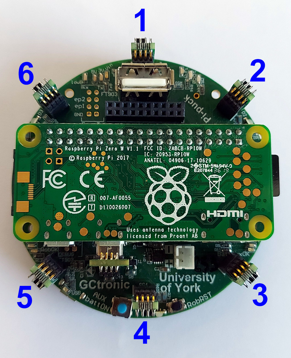
Ultra Wide Band extension for Pi-Puck
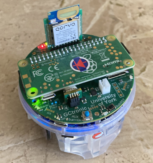
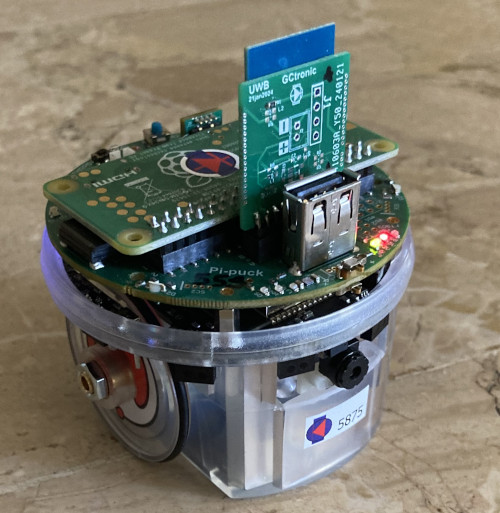
The Ultra Wide Band extension is connected to the Pi-Puck extension through the extension connector pins (2x10). The SPI channel is used for the communication between the Raspberry Pi and the Ultra Wide Band module so that the user is able to configure the module and receive position information from the RPi OS. Here are some examples:
- Anchor configuration: conf_anchor.zip
- Tag configuration: conf_tag.zip
- Get position from tag: tag_get_pos.zip
In order to build the examples the following software package DWM1001_DWM1001-DEV_MDEK1001_Sources_and_Docs_v11.zip need to be downloaded and transferred to the pi-puck system: the examples need to be extracted inside the DWM1001_DWM1001-DEV_MDEK1001_Sources_and_Docs_v11\DWM1001\Source_Code\DWM1001_host_api\dwm1001_host_api\examples directory, then simply issue the make command to build.
The following Android application DRTLS_Manager_R2.apk can also be used to configure the Ultra Wide Band extension.
To get started you need 4 ANCHORS to delimit your arena (see following figure); they are standalone and the Ultra Wide Band extension is equipped with a standard battery connector for easy recharging.
Then you can equip your robots with the Ultra Wide Band extension and by configuring them as TAG you will receive their position inside the arena.
During our test on a 2m x 2m arena with 4 anchors we get position (x, y) accuracy of the e-puck2 robot of about 7cm. Have a look at the following video:
And also with 4 tags: