Pi-puck and Elisa-3 Aseba: Difference between pages
| Line 1: | Line 1: | ||
= | =Introduction= | ||
Aseba is a set of tools which allow novices to program robots easily and efficiently, refer to [https://www.thymio.org/en:start https://www.thymio.org/en:start] for more information. <br/> | |||
== | ==Prerequisites== | ||
The following steps neeed to be done only once: | |||
# The communication between Aseba and Elisa-3 is done through the USB (serial communication is used) cable so you need to install the driver, refer to section [https://www.gctronic.com/doc/index.php/Elisa-3#Requirements Elisa-3 requirements]; in the future we will maybe add RF support too | |||
# [https://projects.gctronic.com/elisa3/aseba-bin-1.5.5-git-b858c2e-win32.exe Download] and install Aseba version '''1.5.5''' | |||
# Download the Elisa-3 target for Aseba [https://projects.gctronic.com/elisa3/elisa3-aseba.hex elisa3-aseba.hex] and upload it to the robot (refer to section [https://www.gctronic.com/doc/index.php/Elisa-3#Programming Elisa-3 Programming]) | |||
= | ==Connection with AsebaStudio== | ||
The following steps explain how to start playing with the Aseba Studio:<br/> | |||
1. Connect the robot to the computer if not already done and turn it on<br/> | |||
2. Download the following script based on your platform and modify its content specifying the AsebaStudio installation folder and the robot port:<br/> | |||
* Windows: [https://projects.gctronic.com/elisa3/asebaswitch_elisa3.bat asebaswitch_elisa3.bat]; spcifiy the installation folder (e.g. <code>C:\Program Files (x86)\AsebaStudio</code>) and the port number (e.g. <code>10</code> for <code>COM10</code>) | |||
* Linux / Mac OS: [https://projects.gctronic.com/elisa3/asebaswitch_elisa3.sh asebaswitch_elisa3.sh]; specifiy the installation folder (e.g. <code>/usr/bin</code> in Linux or <code>/Applications/Aseba/bin</code> in Mac OS) and the port (e.g. <code>/dev/ttyUSB0</code> in Linux or <code>/dev/cu.usbserial-XXXXX</code> in Mac OS) | |||
<!-- # Start the ''asebaswitch'' tool by issueing the command:<br/> <code>asebaswitch -d -v "ser:port=104;baud=57600;stop=1;parity=none;fc=none;bits=8"</code> <br/> you need only to specify the correct <code>port</code> number (''COMx''). The robot will blink if the connection is correctly opened. <br/> For more information about the parameters refer to [https://github.com/aseba-community/dashel/tree/master/docs https://github.com/aseba-community/dashel/tree/master/docs]. <br/> You can find ''asebaswitch'' in the ''AsebaStudio'' installation folder (e.g. <code>C:\Program Files (x86)\AsebaStudio</code>). | |||
--> | |||
3. Start the script: | |||
* Windows: double click on the bat file | |||
* Linux / Mac OS: set the script to be executable with the command <code>chmod +x asebaswitch_elisa3.sh</code> and then execute it <code>./asebaswitch_elisa.sh</code> | |||
4. Start ''AsebaStudio'' and select <code>Network(TCP)</code>, insert <code>localhost</code> as <code>Host</code> and specify <code>33333</code> as <code>Port</code> to open the connection with the robot<br/> | |||
5. If the connection is correctly established you should see the Elisa-3 variables on the left side of ''AsebaStudio'' as shown in the following figure:<br/> | |||
<span class="plainlinks">[https://www.gctronic.com/doc/images/aseba-screenshot2.jpg <img width=400 src="https://www.gctronic.com/doc/images/aseba-screenshot2-small.jpg">]</span> | |||
Have a look also at the following video (you must use the script instead of manually issueing the command as in the video):<br/> | |||
{{#ev:youtube|0jrTgt7F1iM}} | |||
==Simple test== | |||
Once the connection is opened click on the checkbox ''auto'' to start updating the sensors data automatically; we can now interact with the robot, for instance on the left side we can see all the sensors values (proximity, ground, accelerometer, ...) and we can change the motor speed and turn on/off all the leds. | |||
= | =Software= | ||
First of all hava a look at some of the examples proposed in the following section [https://www.gctronic.com/doc/index.php/Elisa-3_Aseba#AsebaStudio_examples AsebaStudio examples].<br/> | |||
Then when you're ready you can start programming the robot on your own, refer to section [https://www.gctronic.com/doc/index.php/Elisa-3_Aseba#Programming_interface Programming interface]; moreover you can have a look at [https://www.thymio.org/en:start https://www.thymio.org/en:start] for more information.<br/> | |||
<font style="color:red">Pay attention that you have 100 bytes availables for your script due to memory constraints.</font><br/> | |||
If you want to have a look behind the scene refer to section [https://www.gctronic.com/doc/index.php/Elisa-3_Aseba#Contribute_to_the_Elisa-3_Aseba_target Contribute to the Elisa-3 Aseba target]. | |||
== | ==AsebaStudio examples== | ||
You can download all the following examples from [https://projects.gctronic.com/elisa3/aseba-elisa3-examples.zip aseba-elisa3-examples.zip]; in order to launch an example follow these steps: | |||
# place the robot selector in position 5. When the robot is turned on, the position of the selector (from 0 to 9) define the node name in ''AsebaStudio'', in our case the node name will be <code>elisa3-5</code> (where ''5'' is the selector position) | |||
# extract the zip, the directory contains some file with ''aesl'' extension, this is the ''AsebaStudio'' code extension | |||
# connect the robot with ''AsebaStudio'' as explained previously | |||
# click on menu <code>File => Open...</code> and select one of the examples extracted from the zip | |||
# click on button <code>Load</code> and then on <code>Run</code>; now the code is running on the robot but it isn't stored in EEPROM, thus when you turn off the robot it returns to its initial state | |||
If you want to save the program in memory you need to click on <code>Tools => Write the program(s)... => inside the elisa3</code> and wait for the programming termination (the green leds around the robot will be turned on while the memory is written); <font style="color:red">pay attention to uncheck the ''auto'' update of the robot variables in ''AsebaStudio'' before starting the writing (with the ''auto'' update enabled the writing could block)</font>.<br/> | |||
=== | ===Simple obstacle avoidance=== | ||
<pre> | |||
var i = 1 | |||
while (i==1) do | |||
if ((prox[0] > 50) or (prox[1] > 50) or (prox[7] > 50)) then | |||
mot.left.target = -20 | |||
mot.right.target = 20 | |||
else | |||
mot.left.target = 20 | |||
mot.right.target = 20 | |||
end | |||
end | |||
</pre> | |||
To fully see the results of this example you need to write the code into the robot. Then let it move with some objects around. | |||
== | ===RGB control=== | ||
<pre> | |||
onevent ir.sensors | |||
if (prox[0] > 20) then # avoid noise | |||
led.rgb[0] = prox[0] | |||
else | |||
led.rgb[0] = 0 | |||
end | |||
if (prox[1] > 20) then # avoid noise | |||
led.rgb[1] = prox[1] | |||
else | |||
led.rgb[1] = 0 | |||
end | |||
if (prox[7] > 20) then # avoid noise | |||
led.rgb[2] = prox[7] | |||
else | |||
led.rgb[2] = 0 | |||
end | |||
</pre> | |||
Once the code is loaded on the robot you can "control" the intensity of the red, green and blue with the ''prox[0]'', ''prox[1]'' and ''prox[7]'' respectively. Try to get the primary and secondary colors ([https://en.wikipedia.org/wiki/Primary_color https://en.wikipedia.org/wiki/Primary_color])...''hint: you need two fingers''. | |||
===Working with events=== | |||
<pre> | |||
var color = 0 | |||
onevent ir.sensors | |||
led.green[0] = 1 - led.green[0] | |||
led.green[2] = 1 - led.green[2] | |||
1. | led.green[4] = 1 - led.green[4] | ||
led.green[6] = 1 - led.green[6] | |||
= | onevent acc | ||
led.green[1] = 1 - led.green[1] | |||
led.green[3] = 1 - led.green[3] | |||
led.green[5] = 1 - led.green[5] | |||
led.green[7] = 1 - led.green[7] | |||
onevent timer | |||
led.rgb[color] = 255 - led.rgb[color] | |||
< | |||
onevent button | |||
if (color == 2) then | |||
color = 0 | |||
else | |||
color++ | |||
end | |||
led.rgb[0] = 0 | |||
led.rgb[1] = 0 | |||
led.rgb[2] = 0 | |||
</pre> | |||
The green leds shows the update frequency of the proximity and accelerometer sensors (you can measure it with an oscilloscope if you have one). You can change the value of the variable <code>timer.period</code> to change the frequency of the RGB LED, the resolution is 1 ms (e.g. by putting 1000 you'll get the RGB LED blinking at 1 Hz). Moreover you can try pressing the button and see what happen (probably you will deduce from the code...). | |||
== | ===Remote control=== | ||
<pre> | |||
onevent rc5 | |||
if rc5 == 2 then # forward | |||
mot.left.target = 20 | |||
mot.right.target = 20 | |||
elseif rc5 == 5 then # stop | |||
mot.left.target = 0 | |||
mot.right.target = 0 | |||
elseif rc5 == 8 then # backward | |||
mot.left.target = -20 | |||
mot.right.target = -20 | |||
elseif rc5 == 4 then # left | |||
mot.left.target = 0 | |||
mot.right.target = 20 | |||
elseif rc5 == 6 then # right | |||
mot.left.target = 20 | |||
mot.right.target = 0 | |||
else # error | |||
led.rgb[0] = 255 | |||
end | |||
</pre> | |||
To fully see the results of this example you need to write the code into the robot. Maybe you should adapt the values used for the various motions and then you can for sure extend the functionalities using others codes (e.g. change RGB LED color). | |||
= | ===Simple local communication=== | ||
== | In this example we need to connect two robots at the same time to ''AsebaStudio'', to accomplish this ''asebaswitch'' need to be called with a different command that is:<br/> | ||
<code>asebaswitch -d -v "ser:port=104;baud=57600;stop=1;parity=none;fc=none;bits=8" "ser:port=69;baud=57600;stop=1;parity=none;fc=none;bits=8"</code><br/> | |||
Basically there are two targets instead of one; you need to specify the correct <code>port</code> number for both the robots. Moreover you need to place the robot receiver selector in position 5 and the robot transmitter selector to another position (from 0 to 9). Both the robots will blink if the connection is correctly opened.<br/> | |||
Load the following code to the receiver robot: | |||
<pre> | |||
call prox.comm.enable(1) | |||
onevent prox.comm | |||
led.green[0] = 0 | |||
led.green[1] = 0 | |||
led.green[2] = 0 | |||
led.green[3] = 0 | |||
led.green[4] = 0 | |||
led.green[5] = 0 | |||
led.green[6] = 0 | |||
led.green[7] = 0 | |||
led.green[prox.comm.rx.id] = 1 | |||
if (prox.comm.rx == 1) then | |||
led.rgb[0] = 255 | |||
led.rgb[1] = 0 | |||
led.rgb[2] = 0 | |||
elseif (prox.comm.rx == 2) then | |||
led.rgb[0] = 0 | |||
led.rgb[1] = 255 | |||
led.rgb[2] = 0 | |||
elseif (prox.comm.rx == 3) then | |||
led.rgb[0] = 0 | |||
led.rgb[1] = 0 | |||
led.rgb[2] = 255 | |||
end | |||
</pre> | |||
Load the following line code to the transmitter robot: | |||
<pre> | |||
call prox.comm.enable(1) | |||
</pre> | |||
Now you can change the <code>prox.comm.tx</code> values (from 1 to 3) on the transmitter tab and see the effect on the receiver robot; also <code>prox.comm.rx</code> and <code>prox.comm.rx.id</code> on the receiver tab will change accordingly. You can easily transform the id to an angle by knowing that each sensor is placed at 45 degrees from each other. Remember to place the robots near each other (< 5 cm). | |||
= | |||
= | |||
< | |||
= | |||
= | |||
== | ===Square path=== | ||
In this example we exploit the onboard odometry to let the robot move in a square path. You have two possibilities: either running on a vertical wall or running on an horizontal plane, both cases are handled automatically. When the Elisa-3 is turned on, it calibrates the sensors (when is placed vertically it rotates around itself for a while with the green led turned on); when the calibration process is finished you can start the square by "touching" the back side proximity. Pay attention that the robot must be placed with the front pointing right when placed vertically. | |||
<div class="toccolours mw-collapsible mw-collapsed"> | |||
<pre> | <pre> | ||
var DISTANCE = 100 # given in mm | |||
var start = 0 | |||
var state = 0 | |||
var isVertical | |||
</pre> | </pre> | ||
<div class="mw-collapsible-content"> | |||
<pre> | |||
sub updateState | |||
if start == 1 then | |||
if (state == 0) then | |||
mot.left.target = 20 | |||
mot.right.target = 20 | |||
led.rgb[0] = 255 | |||
led.rgb[1] = 0 | |||
led.rgb[2] = 0 | |||
if (odom.x >= DISTANCE) then | |||
state = 1 | |||
end | |||
elseif (state == 1) then | |||
mot.left.target = 0 | |||
mot.right.target = 15 | |||
led.rgb[0] = 0 | |||
led.rgb[1] = 255 | |||
led.rgb[2] = 0 | |||
if (odom.theta >= 90) then | |||
state = 2 | |||
end | |||
elseif (state == 2) then | |||
mot.left.target = 20 | |||
mot.right.target = 20 | |||
led.rgb[0] = 0 | |||
led.rgb[1] = 0 | |||
led.rgb[2] = 255 | |||
if (odom.y >= DISTANCE) then | |||
state = 3 | |||
end | |||
elseif (state == 3) then | |||
mot.left.target = 0 | |||
mot.right.target = 20 | |||
led.rgb[0] = 255 | |||
led.rgb[1] = 255 | |||
led.rgb[2] = 0 | |||
call robot.isVertical(isVertical) | |||
if (isVertical == 1) then | |||
if (odom.theta < 0) then | |||
state = 4 | |||
end | |||
else | |||
if (odom.theta >= 180) then | |||
state = 4 | |||
end | |||
end | |||
elseif (state == 4) then | |||
mot.left.target = 20 | |||
mot.right.target = 20 | |||
led.rgb[0] = 255 | |||
led.rgb[1] = 0 | |||
led.rgb[2] = 255 | |||
if (odom.x <= 0) then | |||
state = 5 | |||
end | |||
elseif (state == 5) then | |||
mot.left.target = 0 | |||
mot.right.target = 20 | |||
led.rgb[0] = 0 | |||
led.rgb[1] = 255 | |||
led.rgb[2] = 255 | |||
call robot.isVertical(isVertical) | |||
if (isVertical == 1) then | |||
if ((odom.theta >= -90) and (odom.theta < 0) ) then | |||
state = 6 | |||
end | |||
else | |||
if (odom.theta >= 270) then | |||
state = 6 | |||
end | |||
end | |||
elseif (state == 6) then | |||
mot.left.target = 20 | |||
mot.right.target = 20 | |||
led.rgb[0] = 0 | |||
led.rgb[1] = 0 | |||
led.rgb[2] = 0 | |||
if (odom.y <= 0) then | |||
state = 7 | |||
end | |||
elseif (state == 7) then | |||
mot.left.target = 0 | |||
mot.right.target = 20 | |||
led.rgb[0] = 0 | |||
led.rgb[1] = 0 | |||
led.rgb[2] = 0 | |||
call robot.isVertical(isVertical) | |||
if (isVertical == 1) then | |||
if (odom.theta >= 0) then | |||
state = 8 | |||
end | |||
else | |||
if (odom.theta >= 360) then | |||
state = 8 | |||
end | |||
end | |||
elseif (state == 8) then | |||
mot.left.target = 0 | |||
mot.right.target = 0 | |||
start = 0 | |||
end | |||
end | |||
onevent ir.sensors | |||
if (start == 0) then | |||
if (prox[4] > 200) then | |||
call reset.odometry() | |||
state = 0 | |||
start = 1 | |||
end | |||
end | |||
callsub updateState | |||
</pre> | |||
</div> | |||
</div> | |||
== | |||
= | |||
== | ==Contribute to the Elisa-3 Aseba target== | ||
You can get the source code of the Elisa-3 Aseba target from [https://github.com/aseba-community/aseba-targets-arduino.git github].<br/> | |||
The repo contains all Arduino targets, the Elisa-3 target is placed in the directory ''elisa3''. To build the project follow these steps: | |||
# clone the repo by issueing the command: <code>git clone --recursive https://github.com/gctronic/aseba-targets-arduino.git</code> | |||
# download [https://www.atmel.com/Microsite/atmel-studio/ Atmel Studio 7] since this IDE was used to create the project; the installation of ''Atmel Studio'' includes also the toolchain so you should be able to build the project without any modification | |||
# to open the project double click <code>elisa3-aseba.atsln</code> | |||
= | ===Dependencies=== | ||
The project depends on some files of [https://github.com/aseba-community/aseba Aseba] that is included as submodule in the [https://github.com/aseba-community/aseba-targets-arduino.git aseba-targets-arduino repo] to simplify the building. The files referenced from the project are: | |||
* <code>aseba\trunk\vm\natives.c</code> | |||
* <code>aseba\trunk\vm\natives.h</code> | |||
* <code>aseba\trunk\vm\vm.c</code> | |||
* <code>aseba\trunk\vm\vm.h</code> | |||
* <code>aseba\trunk\transport\buffer\vm-buffer.c</code> | |||
* <code>aseba\trunk\transport\buffer\vm-buffer.h</code> | |||
The project depends also on the Elisa-3 library contained in the [https://www.gctronic.com/doc/index.php/Elisa-3#Advanced_demo ''Elisa-3 advanced firmware revision 221'']. | |||
= | =Programming interface= | ||
This page describes the programming capabilities of Elisa-3. It lists the different <font style="color:red">variables</font>, <font style="color:green">events</font> and <font style="color:blue">functions</font> and indicates to which elements of the robot they refer (see section [https://www.gctronic.com/doc/index.php/Elisa-3#Hardware Hardware] to know where is the actual position on the robot of the sensors and actuators). Each variable is marked with either ''[R]'' or ''[W]'' to indicate whether the variable is used to read a value from the robot or write a value to the robot respectively. This page refers to firmware revision 0 and later.<br/> | |||
< | You can find a document that summarizes the programming interface in the following link [https://projects.gctronic.com/elisa3/elisa3-aseba-cheatsheet.png elisa3-aseba-cheatsheet.png]. | ||
You can | |||
== | ==Standard library== | ||
The | The Elisa-3 comes with the Aseba [https://www.thymio.org/en:asebastdnative standard library of native functions, documented on its own page]. | ||
= | ==Motors== | ||
You can change the wheel speeds by writing in these variables: | |||
* <font style="color:red"><code>motor.left.target</code></font> ''[W]'': requested speed for left wheel | |||
* <font style="color:red"><code>motor.right.target</code></font> ''[W]'': requested speed for right wheel | |||
You can read the real wheel speeds from these variables: | |||
* <font style="color:red"><code>motor.left.speed</code></font> ''[R]'': real speed of left wheel | |||
* <font style="color:red"><code>motor.right.speed</code></font> ''[R]'': real speed of right wheel | |||
The values range from -127 to 127, one unit = 5 mm/s. A value of 127 approximately corresponds to a linear speed of 60 cm/s. | |||
= | ==Green LEDs== | ||
8 green LEDs make up a circle on the bottom of the robot.<br/> | |||
< | <font style="color:red"><code>led.green[0..7]</code></font> ''[W]'': index 0 sets the intensity of the LED at the front of the robot, the others are numbered clockwise. | ||
==RGB LED== | |||
There is one RGB LED in the center of the robot, its light is smoothly spread out through the top diffuser.<br/> | |||
<font style="color:red"><code>led.rgb[0..2]</code></font> ''[W]'': the indexes 0, 1 and 2 set respectively the intensity of the red, green and blue.<br/> | |||
The values range from 0 (off) to 255 (max intensity). | |||
== | ==IR transmitters== | ||
There are 3 IR transmitters pointing upwards, two placed in the front side of the robot and one placed in the back side. You can control their state by writing these variables:<br/> | |||
< | * <font style="color:red"><code>ir.tx.front</code></font> ''[W]'': 0 means that both front IRs are turned off, 1 means that both front IRs are turned on | ||
* <font style="color:red"><code>ir.tx.back</code></font> ''[W]'': 0 means that the back IR is turned off, 1 means that the back IR is turned off | |||
< | |||
==Button== | |||
There is a small button in the back side of the Elisa-3. The variable <font style="color:red"><code>button</code></font> ''[R]'' holds the state of this button (1 = released, 0 = pressed).<br/> | |||
Elisa-3 generates the <font style="color:green"><code>button</code></fonT> event when it is pressed or released. | |||
==Proximity sensors== | |||
Elisa-3 has 8 proximity sensors around its periphery (placed at 45 degrees from each other). Two arrays of 8 variables hold the values of these sensors, the first is <font style="color:red"><code>prox</code></font> ''[R]'' and represents the proximity to an object, the second is <font style="color:red"><code>prox.ambient</code></font> ''[R]'' and represents the ambient light intensity: | |||
* <font style="color:red"><code>prox[0]</code></font>, <font style="color:red"><code>prox.ambient[0]</code></font> : front | |||
* <font style="color:red"><code>prox[1]</code></font>, <font style="color:red"><code>prox.ambient[1]</code></font> : front right | |||
* <font style="color:red"><code>prox[2]</code></font>, <font style="color:red"><code>prox.ambient[2]</code></font> : right | |||
* <font style="color:red"><code>prox[3]</code></font>, <font style="color:red"><code>prox.ambient[3]</code></font> : back right | |||
* <font style="color:red"><code>prox[4]</code></font>, <font style="color:red"><code>prox.ambient[4]</code></font> : back | |||
* <font style="color:red"><code>prox[5]</code></font>, <font style="color:red"><code>prox.ambient[5]</code></font> : back left | |||
* <font style="color:red"><code>prox[6]</code></font>, <font style="color:red"><code>prox.ambient[6]</code></font> : left | |||
* <font style="color:red"><code>prox[7]</code></font>, <font style="color:red"><code>prox.ambient[7]</code></font> : front left | |||
The values in the <font style="color:red"><code>prox</code></font> array vary from 0 (the robot does not see anything) to 255 (the robot is very close to an obstacle); the values of the <font style="color:red"><code>prox.ambient</code></font> array start from 1023 when completely dark and decrease with light increase. Elisa-3 updates these arrays at a frequency of about 80 Hz (when local communication is disabled), and generates the <font style="color:green"><code>ir.sensors</code></font> event after every update. | |||
==Ground sensors== | |||
Elisa-3 holds 4 ground proximity sensors. These sensors are located at the front of the robot. As black grounds appear like no ground at all (black absorbs the infrared light), these sensors can be used to follow a line on the ground and also to avoid falling from the table. Two arrays of 4 variables hold the values of these sensors, the first is <font style="color:red"><code>ground</code></font> ''[R]'' and represents the proximity to the ground or the presence of a black line, the second is <font style="color:red"><code>ground.ambient</code></font> ''[R]'' and represents the ambient light intensity at the ground: | |||
* <font style="color:red"><code>ground[0]</code></font>, <font style="color:red"><code>ground.ambient[0]</code></font> : left | |||
* <font style="color:red"><code>ground[1]</code></font>, <font style="color:red"><code>ground.ambient[1]</code></font> : front left | |||
* <font style="color:red"><code>ground[2]</code></font>, <font style="color:red"><code>ground.ambient[2]</code></font> : front right | |||
* <font style="color:red"><code>ground[3]</code></font>, <font style="color:red"><code>ground.ambient[3]</code></font> : right | |||
The values in the <font style="color:red"><code>ground</code></font> array normally vary from about 600 (white surface) to about 300 (black surface or no ground); the values of the <font style="color:red"><code>prox.ambient</code></font> array start from 1023 when completely dark and decrease with light increase. Elisa-3 updates these arrays at a frequency of about 80 Hz (when local communication is disabled), and generates the same <font style="color:green"><code>ir.sensors</code></font> event after every update. | |||
<font style="color:red"> | ==Accelerometer== | ||
Elisa-3 contains a 3-axes accelerometer. An array of 3 variables, <font style="color:red"><code>acc</code></font> ''[R]'', holds the values of the acceleration along these 3 axes: | |||
* <font style="color:red"><code>acc[0]</code></font> : x-axis (from back to front, positive forward) | |||
* <font style="color:red"><code>acc[1]</code></font> : y-axis (from left to right, positive towards right) | |||
* <font style="color:red"><code>acc[2]</code></font> : z-axis (from bottom to top, positive upward) | |||
The values in this array vary from -128 to 128, with 1 g ([https://en.wikipedia.org/wiki/Earth%27s_gravity the acceleration of the earth's gravity]) corresponding to the value 64. Elisa-3 generates the <font style="color:green"><code>acc</code></font> event after every update.<br/> | |||
The z-axis is used also to know the current orientation of the robot, that is if it is moving vertically or horizontally; the current orientation can be accessed using the function <font style="color:blue"><code>robot.isVertical(dest)</code></font>, where <code>dest</code> will be 1 if it is vertical or 0 if it is horizontal. | |||
== | ==Selector== | ||
The variable <font style="color:red"><code>selector</code></font> ''[R]'' shows the current position of the selector (from 0 to 15). Elisa-3 generates the <font style="color:green"><code>sel</code></font> event everytime its position is changed. | |||
==Remote control== | |||
Elisa-3 contains a receiver for infrared remote controls compatible with the RC5 protocol. When Elisa-3 receives an RC5 code, it generates the <font style="color:green"><code>rc5</code></font> event. In this case, the variables <font style="color:red"><code>rc5</code></font> ''[R]'' is updated. | |||
= | ==Battery== | ||
< | The variable <font style="color:red"><code>bat.percent</code></font> ''[R]'' give you an estimate of the current battery charge given in percentage (100% means you have still a lot of playful time, 0% means you need to wait a little and put the robot in charge). The sampled value can be accessed with the variable <font style="color:red"><code>_bat.adc</code></font> ''[R]'' (this is an hidden variable); the values range from 0 to 1023. | ||
==Local communication== | |||
Elisa-3 can use its infrared proximity sensors to communicate with other robots within a range of about 5 cm. For more detailed information refer to section [https://www.gctronic.com/doc/index.php/Elisa-3#Local_communication Local communication].<br/> | |||
To use the communication, call the <font style="color:blue"><code>prox.comm.enable(state)</code></font> function, with 1 in state to enable communication or 0 to turn it off. If the communication is enabled, the value in the <font style="color:red"><code>prox.comm.tx</code></font> ''[W]'' variable is transmitted to others robots from all the sensors. When Elisa-3 receives a value, the event <font style="color:green"><code>prox.comm</code></font> is fired and the value is in the <font style="color:red"><code>prox.comm.rx</code></font> ''[R]'' variable; moreover the <font style="color:red"><code>prox.comm.rx.id</code></font> ''[R]'' variable contains the id of the sensors (from 0 to 7, where 0 is the front sensor, sensors id increases clockwise) that received the data. | |||
==Odometry== | |||
< | Elisa-3 is capable of estimating how much distance has traveled each wheel resulting in a robot position given in cartesian coordinates (x, y); when moving horizontally the orientation is estimated through the distance traveled by each wheel, instead when moving vertically (what?? vertically?? yes Elisa-3 can move vertically thanks to its magnetic wheels) the orientation is given directly by the accelerometer and it's very precise.<br/> | ||
The variable <font style="color:red"><code>odom.theta</code></font> ''[R]'' contains the current orientation of the robot given in degrees: when moving horizontally the orientation continuously decreases when moving clockwise and continuously increases when moving counter-clockwise; when moving vertically the orientation is from -180 to 180 degrees. The variables <font style="color:red"><code>odom.x</code></font> ''[R]'' and <font style="color:red"><code>odom.y</code></font> ''[R]'' contain the current position of the robot given in millimeters.<br/> | |||
By calling the function <font style="color:blue"><code>reset.odometry</code></font> all the data are reset to zero. | |||
==Timer== | |||
Elisa-3 provides a user-defined timer. The variable <font style="color:red"><code>timer.period</code></font> ''[W]'' allows to specify the period of the timer in milliseconds. The timer starts the countdown when it is initialized (value > 0). When the period expires, the timer generates a <font style="color:green"><code>timer</code></font> event. This events is managed in the same way as all the others and cannot interrupt an already executing event handler. The maximum value is 32767 ms (about 32 seconds). | |||
== | ==Onboard behaviors== | ||
Elisa-3 include two onboard behaviors that can be activated or deactivated at will that are obstacle avoidance and cliff detection. To use obstacle avoidance, call the <font style="color:blue"><code>behavior.oa.enable(state)</code></font> function, with 1 in state to enable obstacle avoidance or 0 to disable it; when activated the motors speed will be adapted in order to avoid obstacles. To use cliff detection, call the <font style="color:blue"><code>behavior.cliff.enable(state)</code></font> function, with 1 in state to enable cliff detection or 0 to disable it; when activated the Elisa-3 will stop as soon as it detect a cliff (pay attention that the robot can detect the void only when going forward). | |||
Revision as of 07:08, 21 February 2024
1 Introduction
Aseba is a set of tools which allow novices to program robots easily and efficiently, refer to https://www.thymio.org/en:start for more information.
1.1 Prerequisites
The following steps neeed to be done only once:
- The communication between Aseba and Elisa-3 is done through the USB (serial communication is used) cable so you need to install the driver, refer to section Elisa-3 requirements; in the future we will maybe add RF support too
- Download and install Aseba version 1.5.5
- Download the Elisa-3 target for Aseba elisa3-aseba.hex and upload it to the robot (refer to section Elisa-3 Programming)
1.2 Connection with AsebaStudio
The following steps explain how to start playing with the Aseba Studio:
1. Connect the robot to the computer if not already done and turn it on
2. Download the following script based on your platform and modify its content specifying the AsebaStudio installation folder and the robot port:
- Windows: asebaswitch_elisa3.bat; spcifiy the installation folder (e.g.
C:\Program Files (x86)\AsebaStudio) and the port number (e.g.10forCOM10) - Linux / Mac OS: asebaswitch_elisa3.sh; specifiy the installation folder (e.g.
/usr/binin Linux or/Applications/Aseba/binin Mac OS) and the port (e.g./dev/ttyUSB0in Linux or/dev/cu.usbserial-XXXXXin Mac OS)
3. Start the script:
- Windows: double click on the bat file
- Linux / Mac OS: set the script to be executable with the command
chmod +x asebaswitch_elisa3.shand then execute it./asebaswitch_elisa.sh
4. Start AsebaStudio and select Network(TCP), insert localhost as Host and specify 33333 as Port to open the connection with the robot
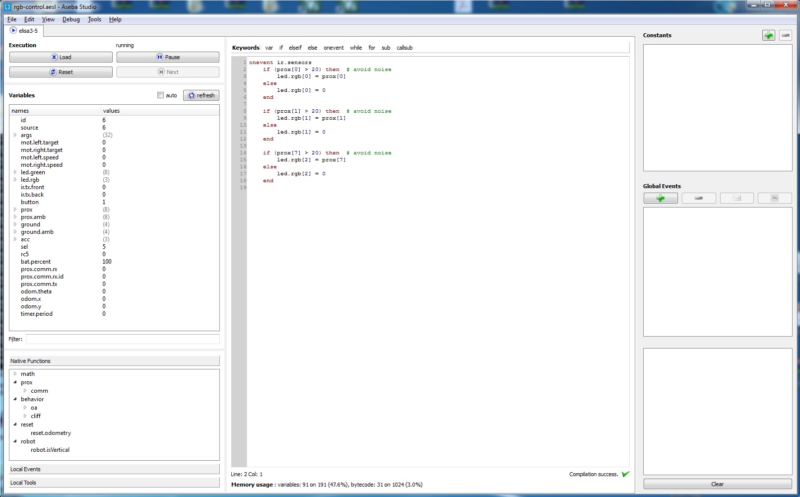
5. If the connection is correctly established you should see the Elisa-3 variables on the left side of AsebaStudio as shown in the following figure:
Have a look also at the following video (you must use the script instead of manually issueing the command as in the video):
1.3 Simple test
Once the connection is opened click on the checkbox auto to start updating the sensors data automatically; we can now interact with the robot, for instance on the left side we can see all the sensors values (proximity, ground, accelerometer, ...) and we can change the motor speed and turn on/off all the leds.
2 Software
First of all hava a look at some of the examples proposed in the following section AsebaStudio examples.
Then when you're ready you can start programming the robot on your own, refer to section Programming interface; moreover you can have a look at https://www.thymio.org/en:start for more information.
Pay attention that you have 100 bytes availables for your script due to memory constraints.
If you want to have a look behind the scene refer to section Contribute to the Elisa-3 Aseba target.
2.1 AsebaStudio examples
You can download all the following examples from aseba-elisa3-examples.zip; in order to launch an example follow these steps:
- place the robot selector in position 5. When the robot is turned on, the position of the selector (from 0 to 9) define the node name in AsebaStudio, in our case the node name will be
elisa3-5(where 5 is the selector position) - extract the zip, the directory contains some file with aesl extension, this is the AsebaStudio code extension
- connect the robot with AsebaStudio as explained previously
- click on menu
File => Open...and select one of the examples extracted from the zip - click on button
Loadand then onRun; now the code is running on the robot but it isn't stored in EEPROM, thus when you turn off the robot it returns to its initial state
If you want to save the program in memory you need to click on Tools => Write the program(s)... => inside the elisa3 and wait for the programming termination (the green leds around the robot will be turned on while the memory is written); pay attention to uncheck the auto update of the robot variables in AsebaStudio before starting the writing (with the auto update enabled the writing could block).
2.1.1 Simple obstacle avoidance
var i = 1
while (i==1) do
	if ((prox[0] > 50) or (prox[1] > 50) or (prox[7] > 50)) then
		mot.left.target = -20
		mot.right.target = 20
	else
		mot.left.target = 20
		mot.right.target = 20
	end
end
To fully see the results of this example you need to write the code into the robot. Then let it move with some objects around.
2.1.2 RGB control
onevent ir.sensors
	if (prox[0] > 20) then	# avoid noise
		led.rgb[0] = prox[0]
	else
		led.rgb[0] = 0
	end

	if (prox[1] > 20) then	# avoid noise
		led.rgb[1] = prox[1]
	else
		led.rgb[1] = 0
	end

	if (prox[7] > 20) then	# avoid noise
		led.rgb[2] = prox[7]
	else
		led.rgb[2] = 0
	end
Once the code is loaded on the robot you can "control" the intensity of the red, green and blue with the prox[0], prox[1] and prox[7] respectively. Try to get the primary and secondary colors (https://en.wikipedia.org/wiki/Primary_color)...hint: you need two fingers.
2.1.3 Working with events
var color = 0

onevent ir.sensors
	led.green[0] = 1 - led.green[0]
	led.green[2] = 1 - led.green[2]
	led.green[4] = 1 - led.green[4]
	led.green[6] = 1 - led.green[6]

onevent acc
	led.green[1] = 1 - led.green[1]
	led.green[3] = 1 - led.green[3]
	led.green[5] = 1 - led.green[5]
	led.green[7] = 1 - led.green[7]

onevent timer
	led.rgb[color] = 255 - led.rgb[color]

onevent button
	if (color == 2) then
		color = 0
	else
		color++
	end
	led.rgb[0] = 0
	led.rgb[1] = 0
	led.rgb[2] = 0
The green leds shows the update frequency of the proximity and accelerometer sensors (you can measure it with an oscilloscope if you have one). You can change the value of the variable timer.period to change the frequency of the RGB LED, the resolution is 1 ms (e.g. by putting 1000 you'll get the RGB LED blinking at 1 Hz). Moreover you can try pressing the button and see what happen (probably you will deduce from the code...).
2.1.4 Remote control
onevent rc5
	if rc5 == 2 then	# forward
		mot.left.target = 20
		mot.right.target = 20
	elseif rc5 == 5 then	# stop
		mot.left.target = 0
		mot.right.target = 0
	elseif rc5 == 8 then	# backward
		mot.left.target = -20
		mot.right.target = -20
	elseif rc5 == 4 then	# left
		mot.left.target = 0
		mot.right.target = 20
	elseif rc5 == 6 then	# right
		mot.left.target = 20
		mot.right.target = 0
	else	# error
		led.rgb[0] = 255
	end
To fully see the results of this example you need to write the code into the robot. Maybe you should adapt the values used for the various motions and then you can for sure extend the functionalities using others codes (e.g. change RGB LED color).
2.1.5 Simple local communication
In this example we need to connect two robots at the same time to AsebaStudio, to accomplish this asebaswitch need to be called with a different command that is:
asebaswitch -d -v "ser:port=104;baud=57600;stop=1;parity=none;fc=none;bits=8" "ser:port=69;baud=57600;stop=1;parity=none;fc=none;bits=8"
Basically there are two targets instead of one; you need to specify the correct port number for both the robots. Moreover you need to place the robot receiver selector in position 5 and the robot transmitter selector to another position (from 0 to 9). Both the robots will blink if the connection is correctly opened.
Load the following code to the receiver robot:
call prox.comm.enable(1)
onevent prox.comm
	led.green[0] = 0
	led.green[1] = 0
	led.green[2] = 0
	led.green[3] = 0
	led.green[4] = 0
	led.green[5] = 0
	led.green[6] = 0
	led.green[7] = 0
	led.green[prox.comm.rx.id] = 1
	if (prox.comm.rx == 1) then
		led.rgb[0] = 255
		led.rgb[1] = 0
		led.rgb[2] = 0
	elseif (prox.comm.rx == 2) then
		led.rgb[0] = 0
		led.rgb[1] = 255
		led.rgb[2] = 0
	elseif (prox.comm.rx == 3) then
		led.rgb[0] = 0
		led.rgb[1] = 0
		led.rgb[2] = 255
	end
Load the following line code to the transmitter robot:
call prox.comm.enable(1)
Now you can change the prox.comm.tx values (from 1 to 3) on the transmitter tab and see the effect on the receiver robot; also prox.comm.rx and prox.comm.rx.id on the receiver tab will change accordingly. You can easily transform the id to an angle by knowing that each sensor is placed at 45 degrees from each other. Remember to place the robots near each other (< 5 cm).
2.1.6 Square path
In this example we exploit the onboard odometry to let the robot move in a square path. You have two possibilities: either running on a vertical wall or running on an horizontal plane, both cases are handled automatically. When the Elisa-3 is turned on, it calibrates the sensors (when is placed vertically it rotates around itself for a while with the green led turned on); when the calibration process is finished you can start the square by "touching" the back side proximity. Pay attention that the robot must be placed with the front pointing right when placed vertically.
var DISTANCE = 100	# given in mm
var start = 0
var state = 0
var isVertical
sub updateState
	if start == 1 then
		if (state == 0) then
			mot.left.target = 20
			mot.right.target = 20
			led.rgb[0] = 255
			led.rgb[1] = 0
			led.rgb[2] = 0
			if (odom.x >= DISTANCE) then
				state = 1
			end
		elseif (state == 1) then
			mot.left.target = 0
			mot.right.target = 15
			led.rgb[0] = 0
			led.rgb[1] = 255
			led.rgb[2] = 0
			if (odom.theta >= 90) then
				state = 2
			end
		elseif (state == 2) then
			mot.left.target = 20
			mot.right.target = 20
			led.rgb[0] = 0
			led.rgb[1] = 0
			led.rgb[2] = 255
			if (odom.y >= DISTANCE) then
				state = 3
			end
		elseif (state == 3) then
			mot.left.target = 0
			mot.right.target = 20
			led.rgb[0] = 255
			led.rgb[1] = 255
			led.rgb[2] = 0
			call robot.isVertical(isVertical)
			if (isVertical == 1) then
				if (odom.theta < 0) then
					state = 4
				end
			else
				if (odom.theta >= 180) then
					state = 4
				end
			end
		elseif (state == 4) then
			mot.left.target = 20
			mot.right.target = 20
			led.rgb[0] = 255
			led.rgb[1] = 0
			led.rgb[2] = 255
			if (odom.x <= 0) then
				state = 5
			end
		elseif (state == 5) then
			mot.left.target = 0
			mot.right.target = 20
			led.rgb[0] = 0
			led.rgb[1] = 255
			led.rgb[2] = 255
			call robot.isVertical(isVertical)
			if (isVertical == 1) then
				if ((odom.theta >= -90) and (odom.theta < 0) ) then
					state = 6
				end
			else
				if (odom.theta >= 270) then
					state = 6
				end
			end
		elseif (state == 6) then
			mot.left.target = 20
			mot.right.target = 20
			led.rgb[0] = 0
			led.rgb[1] = 0
			led.rgb[2] = 0
			if (odom.y <= 0) then
				state = 7
			end
		elseif (state == 7) then
			mot.left.target = 0
			mot.right.target = 20
			led.rgb[0] = 0
			led.rgb[1] = 0
			led.rgb[2] = 0
			call robot.isVertical(isVertical)
			if (isVertical == 1) then
				if (odom.theta >= 0) then
					state = 8
				end
			else
				if (odom.theta >= 360) then
					state = 8
				end
			end
		elseif (state == 8) then
			mot.left.target = 0
			mot.right.target = 0
			start = 0
		end
	end

onevent ir.sensors
	if (start == 0) then
		if (prox[4] > 200) then
			call reset.odometry()
			state = 0
			start = 1
		end
	end
	callsub updateState
2.2 Contribute to the Elisa-3 Aseba target
You can get the source code of the Elisa-3 Aseba target from github.
The repo contains all Arduino targets, the Elisa-3 target is placed in the directory elisa3. To build the project follow these steps:
- clone the repo by issueing the command:
git clone --recursive https://github.com/gctronic/aseba-targets-arduino.git - download Atmel Studio 7 since this IDE was used to create the project; the installation of Atmel Studio includes also the toolchain so you should be able to build the project without any modification
- to open the project double click
elisa3-aseba.atsln
2.2.1 Dependencies
The project depends on some files of Aseba that is included as submodule in the aseba-targets-arduino repo to simplify the building. The files referenced from the project are:
aseba\trunk\vm\natives.caseba\trunk\vm\natives.haseba\trunk\vm\vm.caseba\trunk\vm\vm.haseba\trunk\transport\buffer\vm-buffer.caseba\trunk\transport\buffer\vm-buffer.h
The project depends also on the Elisa-3 library contained in the Elisa-3 advanced firmware revision 221.
3 Programming interface
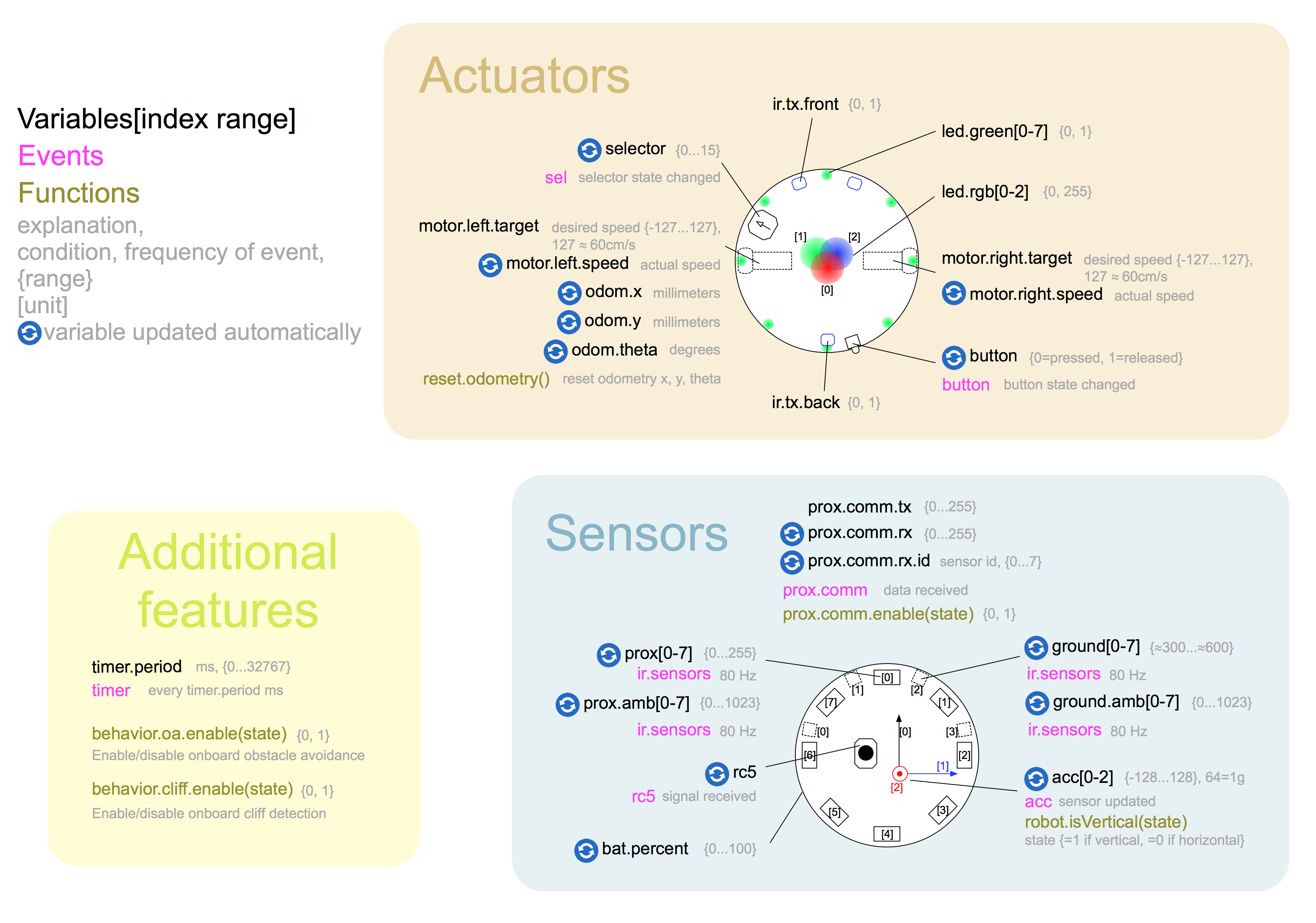
This page describes the programming capabilities of Elisa-3. It lists the different variables, events and functions and indicates to which elements of the robot they refer (see section Hardware to know where is the actual position on the robot of the sensors and actuators). Each variable is marked with either [R] or [W] to indicate whether the variable is used to read a value from the robot or write a value to the robot respectively. This page refers to firmware revision 0 and later.
You can find a document that summarizes the programming interface in the following link elisa3-aseba-cheatsheet.png.
3.1 Standard library
The Elisa-3 comes with the Aseba standard library of native functions, documented on its own page.
3.2 Motors
You can change the wheel speeds by writing in these variables:
motor.left.target[W]: requested speed for left wheelmotor.right.target[W]: requested speed for right wheel
You can read the real wheel speeds from these variables:
motor.left.speed[R]: real speed of left wheelmotor.right.speed[R]: real speed of right wheel
The values range from -127 to 127, one unit = 5 mm/s. A value of 127 approximately corresponds to a linear speed of 60 cm/s.
3.3 Green LEDs
8 green LEDs make up a circle on the bottom of the robot.
led.green[0..7] [W]: index 0 sets the intensity of the LED at the front of the robot, the others are numbered clockwise.
3.4 RGB LED
There is one RGB LED in the center of the robot, its light is smoothly spread out through the top diffuser.
led.rgb[0..2] [W]: the indexes 0, 1 and 2 set respectively the intensity of the red, green and blue.
The values range from 0 (off) to 255 (max intensity).
3.5 IR transmitters
There are 3 IR transmitters pointing upwards, two placed in the front side of the robot and one placed in the back side. You can control their state by writing these variables:
ir.tx.front[W]: 0 means that both front IRs are turned off, 1 means that both front IRs are turned onir.tx.back[W]: 0 means that the back IR is turned off, 1 means that the back IR is turned off
3.6 Button
There is a small button in the back side of the Elisa-3. The variable button [R] holds the state of this button (1 = released, 0 = pressed).
Elisa-3 generates the button event when it is pressed or released.
3.7 Proximity sensors
Elisa-3 has 8 proximity sensors around its periphery (placed at 45 degrees from each other). Two arrays of 8 variables hold the values of these sensors, the first is prox [R] and represents the proximity to an object, the second is prox.ambient [R] and represents the ambient light intensity:
prox[0],prox.ambient[0]: frontprox[1],prox.ambient[1]: front rightprox[2],prox.ambient[2]: rightprox[3],prox.ambient[3]: back rightprox[4],prox.ambient[4]: backprox[5],prox.ambient[5]: back leftprox[6],prox.ambient[6]: leftprox[7],prox.ambient[7]: front left
The values in the prox array vary from 0 (the robot does not see anything) to 255 (the robot is very close to an obstacle); the values of the prox.ambient array start from 1023 when completely dark and decrease with light increase. Elisa-3 updates these arrays at a frequency of about 80 Hz (when local communication is disabled), and generates the ir.sensors event after every update.
3.8 Ground sensors
Elisa-3 holds 4 ground proximity sensors. These sensors are located at the front of the robot. As black grounds appear like no ground at all (black absorbs the infrared light), these sensors can be used to follow a line on the ground and also to avoid falling from the table. Two arrays of 4 variables hold the values of these sensors, the first is ground [R] and represents the proximity to the ground or the presence of a black line, the second is ground.ambient [R] and represents the ambient light intensity at the ground:
ground[0],ground.ambient[0]: leftground[1],ground.ambient[1]: front leftground[2],ground.ambient[2]: front rightground[3],ground.ambient[3]: right
The values in the ground array normally vary from about 600 (white surface) to about 300 (black surface or no ground); the values of the prox.ambient array start from 1023 when completely dark and decrease with light increase. Elisa-3 updates these arrays at a frequency of about 80 Hz (when local communication is disabled), and generates the same ir.sensors event after every update.
3.9 Accelerometer
Elisa-3 contains a 3-axes accelerometer. An array of 3 variables, acc [R], holds the values of the acceleration along these 3 axes:
acc[0]: x-axis (from back to front, positive forward)acc[1]: y-axis (from left to right, positive towards right)acc[2]: z-axis (from bottom to top, positive upward)
The values in this array vary from -128 to 128, with 1 g (the acceleration of the earth's gravity) corresponding to the value 64. Elisa-3 generates the acc event after every update.
The z-axis is used also to know the current orientation of the robot, that is if it is moving vertically or horizontally; the current orientation can be accessed using the function robot.isVertical(dest), where dest will be 1 if it is vertical or 0 if it is horizontal.
3.10 Selector
The variable selector [R] shows the current position of the selector (from 0 to 15). Elisa-3 generates the sel event everytime its position is changed.
3.11 Remote control
Elisa-3 contains a receiver for infrared remote controls compatible with the RC5 protocol. When Elisa-3 receives an RC5 code, it generates the rc5 event. In this case, the variables rc5 [R] is updated.
3.12 Battery
The variable bat.percent [R] give you an estimate of the current battery charge given in percentage (100% means you have still a lot of playful time, 0% means you need to wait a little and put the robot in charge). The sampled value can be accessed with the variable _bat.adc [R] (this is an hidden variable); the values range from 0 to 1023.
3.13 Local communication
Elisa-3 can use its infrared proximity sensors to communicate with other robots within a range of about 5 cm. For more detailed information refer to section Local communication.
To use the communication, call the prox.comm.enable(state) function, with 1 in state to enable communication or 0 to turn it off. If the communication is enabled, the value in the prox.comm.tx [W] variable is transmitted to others robots from all the sensors. When Elisa-3 receives a value, the event prox.comm is fired and the value is in the prox.comm.rx [R] variable; moreover the prox.comm.rx.id [R] variable contains the id of the sensors (from 0 to 7, where 0 is the front sensor, sensors id increases clockwise) that received the data.
3.14 Odometry
Elisa-3 is capable of estimating how much distance has traveled each wheel resulting in a robot position given in cartesian coordinates (x, y); when moving horizontally the orientation is estimated through the distance traveled by each wheel, instead when moving vertically (what?? vertically?? yes Elisa-3 can move vertically thanks to its magnetic wheels) the orientation is given directly by the accelerometer and it's very precise.
The variable odom.theta [R] contains the current orientation of the robot given in degrees: when moving horizontally the orientation continuously decreases when moving clockwise and continuously increases when moving counter-clockwise; when moving vertically the orientation is from -180 to 180 degrees. The variables odom.x [R] and odom.y [R] contain the current position of the robot given in millimeters.
By calling the function reset.odometry all the data are reset to zero.
3.15 Timer
Elisa-3 provides a user-defined timer. The variable timer.period [W] allows to specify the period of the timer in milliseconds. The timer starts the countdown when it is initialized (value > 0). When the period expires, the timer generates a timer event. This events is managed in the same way as all the others and cannot interrupt an already executing event handler. The maximum value is 32767 ms (about 32 seconds).
3.16 Onboard behaviors
Elisa-3 include two onboard behaviors that can be activated or deactivated at will that are obstacle avoidance and cliff detection. To use obstacle avoidance, call the behavior.oa.enable(state) function, with 1 in state to enable obstacle avoidance or 0 to disable it; when activated the motors speed will be adapted in order to avoid obstacles. To use cliff detection, call the behavior.cliff.enable(state) function, with 1 in state to enable cliff detection or 0 to disable it; when activated the Elisa-3 will stop as soon as it detect a cliff (pay attention that the robot can detect the void only when going forward).