Aseba is a set of tools which allow novices to program robots easily and efficiently, refer to [https://www.thymio.org/en:start https://www.thymio.org/en:start] for more information. <br/>
=Robot configuration=
==Prerequisites==
This section explains how to configure the robot based on the communication channel you will use for your developments, thus you need to read only one of the following sections, but it would be better if you spend a bit of time reading them all in order to have a full understanding of the available configurations.
The following steps neeed to be done only once:
# The communication between Aseba and Elisa-3 is done through the USB (serial communication is used) cable so you need to install the driver, refer to section [https://www.gctronic.com/doc/index.php/Elisa-3#Requirements Elisa-3 requirements]; in the future we will maybe add RF support too
# Download ([https://projects.gctronic.com/elisa3/aseba-1.6.1.exe Windows], [https://projects.gctronic.com/elisa3/aseba_1.6.1_amd64.deb Linux], [https://projects.gctronic.com/elisa3/Aseba-1.6.1.dmg Mac]) and install Aseba version '''1.6.1'''
# Download the Elisa-3 target for Aseba [https://projects.gctronic.com/elisa3/elisa3-aseba.hex elisa3-aseba.hex] and upload it to the robot (refer to section [https://www.gctronic.com/doc/index.php/Elisa-3#Programming Elisa-3 Programming])
==USB==
==Connection with AsebaStudio==
The main microcontroller is initially programmed with a firmware that support USB communication.<br/>
The following steps explain how to start playing with the Aseba Studio:<br/>
1. Connect the robot to the computer if not already done and turn it on<br/>
2. Download the following script based on your platform and modify its content specifying the AsebaStudio installation folder and the robot port:<br/>
* Windows: [https://projects.gctronic.com/elisa3/asebaswitch_elisa3.bat asebaswitch_elisa3.zip]; decompress it and spcifiy the installation folder (e.g. <code>C:\Program Files (x86)\AsebaStudio</code>) and the port number (e.g. <code>10</code> for <code>COM10</code>)
* Linux / Mac OS: [https://projects.gctronic.com/elisa3/asebaswitch_elisa3.sh asebaswitch_elisa3.sh]; specifiy the installation folder (e.g. <code>/usr/bin</code> in Linux or <code>/Applications/Aseba/bin</code> in Mac OS) and the port (e.g. <code>/dev/ttyUSB0</code> in Linux or <code>/dev/cu.usbserial-XXXXX</code> in Mac OS)
<!-- # Start the ''asebaswitch'' tool by issueing the command:<br/> <code>asebaswitch -d -v "ser:port=104;baud=57600;stop=1;parity=none;fc=none;bits=8"</code> <br/> you need only to specify the correct <code>port</code> number (''COMx''). The robot will blink if the connection is correctly opened. <br/> For more information about the parameters refer to [https://github.com/aseba-community/dashel/tree/master/docs https://github.com/aseba-community/dashel/tree/master/docs]. <br/> You can find ''asebaswitch'' in the ''AsebaStudio'' installation folder (e.g. <code>C:\Program Files (x86)\AsebaStudio</code>).
-->
3. Start the script:
* Windows: double click on the bat file
* Linux / Mac OS: set the script to be executable with the command <code>chmod +x asebaswitch_elisa3.sh</code> and then execute it <code>./asebaswitch_elisa.sh</code>
4. Start ''AsebaStudio'' and select <code>Network(TCP)</code>, insert <code>localhost</code> as <code>Host</code> and specify <code>33333</code> as <code>Port</code> to open the connection with the robot<br/>
5. If the connection is correctly established you should see the Elisa-3 variables on the left side of ''AsebaStudio'' as shown in the following figure:<br/>
If the main microcontroller isn't programmed with the factory firmware or if you want to be sure to have the last firmware on the robot, you need to program it with the last factory firmware by referring to section [https://www.gctronic.com/doc/index.php?title=e-puck2#Firmware_update main microcontroller firmware update].<br/>
Have a look also at the following video (you must use the script instead of manually issueing the command as in the video):<br/>
{{#ev:youtube|0jrTgt7F1iM}}
The radio module can be programmed with either the <code>Bluetooth</code> or the <code>WiFi</code> firmware, both are compatible with USB communication:
==Simple test==
* Bluetooth: refer to section [https://www.gctronic.com/doc/index.php?title=e-puck2#Firmware_update_2 radio module firmware update]
Once the connection is opened click on the checkbox ''auto'' to start updating the sensors data automatically; we can now interact with the robot, for instance on the left side we can see all the sensors values (proximity, ground, accelerometer, ...) and we can change the motor speed and turn on/off all the leds.
* WiFi: download the [https://projects.gctronic.com/epuck2/esp32-firmware-wifi_25.02.19_e2f4883.zip radio module wifi firmware (25.02.19)] and then refer to section [https://www.gctronic.com/doc/index.php?title=e-puck2#Firmware_update_2 radio module firmware update]
When you want to interact with the robot from the computer you need to place the selector in position 8 to work with USB. <br/>
=Software=
First of all hava a look at some of the examples proposed in the following section [https://www.gctronic.com/doc/index.php/Elisa-3_Aseba#AsebaStudio_examples AsebaStudio examples].<br/>
Then when you're ready you can start programming the robot on your own, refer to section [https://www.gctronic.com/doc/index.php/Elisa-3_Aseba#Programming_interface Programming interface]; moreover you can have a look at [https://www.thymio.org/en:start https://www.thymio.org/en:start] for more information.<br/>
<font style="color:red">Pay attention that you have 100 bytes availables for your script due to memory constraints.</font><br/>
If you want to have a look behind the scene refer to section [https://www.gctronic.com/doc/index.php/Elisa-3_Aseba#Contribute_to_the_Elisa-3_Aseba_target Contribute to the Elisa-3 Aseba target].
Section [https://www.gctronic.com/doc/index.php?title=e-puck2#PC_interface PC interface] gives step by step instructions on how to connect the robot with the computer via USB.<br/>
==AsebaStudio examples==
You can download all the following examples from [https://projects.gctronic.com/elisa3/aseba-elisa3-examples.zip aseba-elisa3-examples.zip]; in order to launch an example follow these steps:
# place the robot selector in position 5. When the robot is turned on, the position of the selector (from 0 to 9) define the node name in ''AsebaStudio'', in our case the node name will be <code>elisa3-5</code> (where ''5'' is the selector position)
# extract the zip, the directory contains some file with ''aesl'' extension, this is the ''AsebaStudio'' code extension
# connect the robot with ''AsebaStudio'' as explained previously
# click on menu <code>File => Open...</code> and select one of the examples extracted from the zip
# click on button <code>Load</code> and then on <code>Run</code>; now the code is running on the robot but it isn't stored in EEPROM, thus when you turn off the robot it returns to its initial state
If you want to save the program in memory you need to click on <code>Tools => Write the program(s)... => inside the elisa3</code> and wait for the programming termination (the green leds around the robot will be turned on while the memory is written); <font style="color:red">pay attention to uncheck the ''auto'' update of the robot variables in ''AsebaStudio'' before starting the writing (with the ''auto'' update enabled the writing could block)</font>.<br/>
Once you tested the connection with the robot and the computer, you can start developing your own application by looking at the details behind the communication protocol. Both USB and Bluetooth communication channels use the same protocol called [https://www.gctronic.com/doc/index.php?title=e-puck2_PC_side_development#Bluetooth_and_USB advanced sercom v2], refer to section [https://www.gctronic.com/doc/index.php?title=e-puck2_PC_side_development#Bluetooth_and_USB_2 Communication protocol: BT and USB] for detailed information about this protocol.<br/>
===Simple obstacle avoidance===
<pre>
var i = 1
while (i==1) do
	if ((prox[0] > 50) or (prox[1] > 50) or (prox[7] > 50)) then
		mot.left.target = -20
		mot.right.target = 20
	else
		mot.left.target = 20
		mot.right.target = 20
	end
end
</pre>
To fully see the results of this example you need to write the code into the robot. Then let it move with some objects around.
==Bluetooth==
===RGB control===
The main microcontroller and radio module of the robot are initially programmed with firmwares that together support Bluetooth communication.<br/>
<pre>
onevent ir.sensors
	if (prox[0] > 20) then	# avoid noise
		led.rgb[0] = prox[0]
	else
		led.rgb[0] = 0
	end

	if (prox[1] > 20) then	# avoid noise
		led.rgb[1] = prox[1]
	else
		led.rgb[1] = 0
	end

	if (prox[7] > 20) then	# avoid noise
		led.rgb[2] = prox[7]
	else
		led.rgb[2] = 0
	end
</pre>
If the main microcontroller and radio module aren't programmed with the factory firmware or if you want to be sure to have the last firmwares on the robot, you need to program them with the last factory firmwares:
Once the code is loaded on the robot you can "control" the intensity of the red, green and blue with the ''prox[0]'', ''prox[1]'' and ''prox[7]'' respectively. Try to get the primary and secondary colors ([https://en.wikipedia.org/wiki/Primary_color https://en.wikipedia.org/wiki/Primary_color])...''hint: you need two fingers''.
* for the main microcontroller, refer to section [https://www.gctronic.com/doc/index.php?title=e-puck2#Firmware_update main microcontroller firmware update]
* for the radio module, refer to section [https://www.gctronic.com/doc/index.php?title=e-puck2#Firmware_update_2 radio module firmware update]
When you want to interact with the robot from the computer you need to place the selector in position 3 if you want to work with Bluetooth. <br/>
===Working with events===
<pre>
var color = 0
Section [https://www.gctronic.com/doc/index.php?title=e-puck2_PC_side_development#Connecting_to_the_Bluetooth Connecting to the Bluetooth] gives step by step instructions on how to accomplish your first Bluetooth connection with the robot.<br/>
onevent ir.sensors
led.green[0] = 1 - led.green[0]
led.green[2] = 1 - led.green[2]
led.green[4] = 1 - led.green[4]
led.green[6] = 1 - led.green[6]
Once you tested the connection with the robot and the computer, you can start developing your own application by looking at the details behind the communication protocol. Both Bluetooth and USB communication channels use the same protocol called [https://www.gctronic.com/doc/index.php?title=e-puck2_PC_side_development#Bluetooth_and_USB advanced sercom v2], refer to section [https://www.gctronic.com/doc/index.php?title=e-puck2_PC_side_development#Bluetooth_and_USB Communication protocol: BT and USB] for detailed information about this protocol.<br/>
onevent acc
led.green[1] = 1 - led.green[1]
led.green[3] = 1 - led.green[3]
led.green[5] = 1 - led.green[5]
led.green[7] = 1 - led.green[7]
==WiFi==
onevent timer
For working with the WiFi, the main microcontroller must be programmed with the factory firmware and the radio module must be programmed with a dedicated firmware (not the factory one):
led.rgb[color] = 255 - led.rgb[color]
* for the main microcontroller, refer to section [https://www.gctronic.com/doc/index.php?title=e-puck2#Firmware_update main microcontroller firmware update]
* [https://projects.gctronic.com/epuck2/esp32-firmware-wifi_25.02.19_e2f4883.zip radio module wifi firmware (25.02.19)], for information on how to update the firmware refer to section [https://www.gctronic.com/doc/index.php?title=e-puck2#Firmware_update_2 radio module firmware update]
onevent button
Put the selector in position 15(F).<br/>
if (color == 2) then
color = 0
else
color++
end
led.rgb[0] = 0
led.rgb[1] = 0
led.rgb[2] = 0
</pre>
The green leds shows the update frequency of the proximity and accelerometer sensors (you can measure it with an oscilloscope if you have one). You can change the value of the variable <code>timer.period</code> to change the frequency of the RGB LED, the resolution is 1 ms (e.g. by putting 1000 you'll get the RGB LED blinking at 1 Hz). Moreover you can try pressing the button and see what happen (probably you will deduce from the code...).
Section [https://www.gctronic.com/doc/index.php?title=e-puck2_PC_side_development#Connecting_to_the_WiFi Connecting to the WiFi] gives step by step instructions on how to accomplish your first WiFi connection with the robot.<br/>
===Remote control===
<pre>
onevent rc5
	if rc5 == 2 then	# forward
		mot.left.target = 20
		mot.right.target = 20
	elseif rc5 == 5 then	# stop
		mot.left.target = 0
		mot.right.target = 0
	elseif rc5 == 8 then	# backward
		mot.left.target = -20
		mot.right.target = -20
	elseif rc5 == 4 then	# left
		mot.left.target = 0
		mot.right.target = 20
	elseif rc5 == 6 then	# right
		mot.left.target = 20
		mot.right.target = 0
	else	# error
		led.rgb[0] = 255
	end
</pre>
To fully see the results of this example you need to write the code into the robot. Maybe you should adapt the values used for the various motions and then you can for sure extend the functionalities using others codes (e.g. change RGB LED color).
The communication protocol is described in detail in the section [https://www.gctronic.com/doc/index.php?title=e-puck2_PC_side_development#WiFi_2 Communication protocol: WiFi].<br/>
===Simple local communication===
In this example we need to connect two robots at the same time to ''AsebaStudio'', to accomplish this ''asebaswitch'' need to be called with a different command that is:<br/>
Basically there are two targets instead of one; you need to specify the correct <code>port</code> number for both the robots. Moreover you need to place the robot receiver selector in position 5 and the robot transmitter selector to another position (from 0 to 9). Both the robots will blink if the connection is correctly opened.<br/>
Load the following code to the receiver robot:
<pre>
call prox.comm.enable(1)
onevent prox.comm
	led.green[0] = 0
	led.green[1] = 0
	led.green[2] = 0
	led.green[3] = 0
	led.green[4] = 0
	led.green[5] = 0
	led.green[6] = 0
	led.green[7] = 0
	led.green[prox.comm.rx.id] = 1
	if (prox.comm.rx == 1) then
		led.rgb[0] = 255
		led.rgb[1] = 0
		led.rgb[2] = 0
	elseif (prox.comm.rx == 2) then
		led.rgb[0] = 0
		led.rgb[1] = 255
		led.rgb[2] = 0
	elseif (prox.comm.rx == 3) then
		led.rgb[0] = 0
		led.rgb[1] = 0
		led.rgb[2] = 255
	end
</pre>
Load the following line code to the transmitter robot:
<pre>
call prox.comm.enable(1)
</pre>
Now you can change the <code>prox.comm.tx</code> values (from 1 to 3) on the transmitter tab and see the effect on the receiver robot; also <code>prox.comm.rx</code> and <code>prox.comm.rx.id</code> on the receiver tab will change accordingly. You can easily transform the id to an angle by knowing that each sensor is placed at 45 degrees from each other. Remember to place the robots near each other (< 5 cm).
=Connecting to the Bluetooth=
===Square path===
In this example we exploit the onboard odometry to let the robot move in a square path. You have two possibilities: either running on a vertical wall or running on an horizontal plane, both cases are handled automatically. When the Elisa-3 is turned on, it calibrates the sensors (when is placed vertically it rotates around itself for a while with the green led turned on); when the calibration process is finished you can start the square by "touching" the back side proximity. Pay attention that the robot must be placed with the front pointing right when placed vertically.
if ((odom.theta >= -90) and (odom.theta < 0) ) then
state = 6
end
else
if (odom.theta >= 270) then
state = 6
end
end
elseif (state == 6) then
mot.left.target = 20
mot.right.target = 20
led.rgb[0] = 0
led.rgb[1] = 0
led.rgb[2] = 0
if (odom.y <= 0) then
state = 7
end
elseif (state == 7) then
mot.left.target = 0
mot.right.target = 20
led.rgb[0] = 0
led.rgb[1] = 0
led.rgb[2] = 0
call robot.isVertical(isVertical)
if (isVertical == 1) then
if (odom.theta >= 0) then
state = 8
end
else
if (odom.theta >= 360) then
state = 8
end
end
elseif (state == 8) then
mot.left.target = 0
mot.right.target = 0
start = 0
end
end
The factory firmware of the radio module creates 3 Bluetooth channels using the RFcomm protocol when the robot is paired with the computer:
onevent ir.sensors
# Channel 1, GDB: port to connect with GDB if the programmer is in mode 1 or 3 (refer to chapter [https://www.gctronic.com/doc/index.php?title=e-puck2_programmer_development#Configuring_the_Programmer.27s_settings Configuring the Programmer's settings] for more information about these modes)
if (start == 0) then
# Channel 2, UART: port to connect to the UART port of the main processor
if (prox[4] > 200) then
# Channel 3, SPI: port to connect to the SPI port of the main processor (not yet implemented. Just do an echo for now)
call reset.odometry()
state = 0
By default, the e-puck2 is not visible when you search for it in the Bluetooth utility of your computer.<br>
start = 1
'''To make it visible, it is necessary to hold the USER button (also labeled "esp32" on the electronic board) while turning on the robot with the ON/OFF button.'''<br>
Then it will be discoverable and you will be able to pair with it.<br>
callsub updateState
Note that a prompt could ask you to confirm that the number written on the screen is the same on the e-puck. just ignore this and accept. Otherwise if you are asked for a pin insert 0000.
</pre>
</div>
</div>
==Windows 7==
==Contribute to the Elisa-3 Aseba target==
When you pair your computer with the e-puck2, 3 COM ports will be automatically created.
You can get the source code of the Elisa-3 Aseba target from [https://github.com/aseba-community/aseba-targets-arduino.git github].<br/>
To see which COM port corresponds to which channel you need to open the properties of the paired e-puck2 robot from <code>Bluetooth devices</code>. Then the ports and related channels are listed in the <code>Services</code> tab, as shown in the following figure:<br/>
The repo contains all Arduino targets, the Elisa-3 target is placed in the directory ''elisa3''. To build the project follow these steps:
# clone the repo by issueing the command: <code>git clone --recursive https://github.com/gctronic/aseba-targets-arduino.git</code>
# download [https://www.atmel.com/Microsite/atmel-studio/ Atmel Studio 7] since this IDE was used to create the project; the installation of ''Atmel Studio'' includes also the toolchain so you should be able to build the project without any modification
# to open the project double click <code>elisa3-aseba.atsln</code>
==Windows 10==
===Dependencies===
When you pair your computer with the e-puck2, 6 COM ports will be automatically created. The three ports you will use have <code>Outgoing</code> direction and are named <code>e_puck2_xxxxx-GDB</code>, <code>e_puck2_xxxxx-UART</code>, <code>e_puck2_xxxxx-SPI</code>. <code>xxxxx</code> is the ID number of your e-puck2.<br/>
The project depends on some files of [https://github.com/aseba-community/aseba Aseba] that is included as submodule in the [https://github.com/aseba-community/aseba-targets-arduino.git aseba-targets-arduino repo] to simplify the building. The files referenced from the project are:
To see which COM port corresponds to which channel you need to:
* <code>aseba\trunk\vm\natives.c</code>
# open the Bluetooth devices manager
* <code>aseba\trunk\vm\natives.h</code>
# pair with the robot
* <code>aseba\trunk\vm\vm.c</code>
# click on <code>More Bluetooth options</code>
* <code>aseba\trunk\vm\vm.h</code>
# the ports and related channels are listed in the <code>COM Ports</code> tab, as shown in the following figure:<br/>
The project depends also on the Elisa-3 library contained in the [https://www.gctronic.com/doc/index.php/Elisa-3#Advanced_demo ''Elisa-3 advanced firmware revision 221''].
Once paired with the Bluetooth manager, you need to create the port for communicating with the robot by issueing the command: <br/>
The MAC address is visible from the Bluetooth manager. The parameter <code>2</code> indicates the channel, in this case a port for the <code>UART</code> channel is created. If you want to connect to another service you need to change this parameter accordingly (e.g. <code>1</code> for <code>GDB</code> and <code>3</code> for <code>SPI</code>). Now you can use <code>/dev/rfcomm0</code> to connect to the robot.
==Mac==
=Programming interface=
When you pair your computer with the e-puck2, 3 COM ports will be automatically created: <code>/dev/cu.e-puck2_xxxxx-GDB</code>, <code>/dev/cu.e-puck2_xxxxx-UART</code> and <code>/dev/cu.e-puck2_xxxxx-SPI</code>. xxxxx is the ID number of your e-puck2.
This page describes the programming capabilities of Elisa-3. It lists the different <font style="color:red">variables</font>, <font style="color:green">events</font> and <font style="color:blue">functions</font> and indicates to which elements of the robot they refer (see section [https://www.gctronic.com/doc/index.php/Elisa-3#Hardware Hardware] to know where is the actual position on the robot of the sensors and actuators). Each variable is marked with either ''[R]'' or ''[W]'' to indicate whether the variable is used to read a value from the robot or write a value to the robot respectively. This page refers to firmware revision 0 and later.<br/>
You can find a document that summarizes the programming interface in the following link [https://projects.gctronic.com/elisa3/elisa3-aseba-cheatsheet.png elisa3-aseba-cheatsheet.png].
==Testing the Bluetooth connection==
==Standard library==
You need to download the PC application provided in section [https://www.gctronic.com/doc/index.php?title=e-puck2#Available_executables PC interface: available executables].<br/>
The Elisa-3 comes with the Aseba [https://www.thymio.org/en:asebastdnative standard library of native functions, documented on its own page].
In the connection textfield you need to enter the UART channel port, for example:
* Windows 7: <code>COM258</code>
* Windows 10: <code>e_puck2_xxxxx-UART</code>
* Linux: <code>/dev/rfcomm0</code>
* Mac: <code>/dev/cu.e-puck2_xxxxx-UART</code>
and then click <code>Connect</code>. <br/>
You should start receiving sensors data and you can send commands to the robot.<br/>
Alternatively you can also use a simple terminal program (e.g. <code>realterm</code> in Windows) instead of the PC application, then you can issue manually the commands to receive sensors data or for setting the actuators (once connected, type <code>h + ENTER</code> for a list of availables commands).
==Motors==
You can change the wheel speeds by writing in these variables:
* <font style="color:red"><code>motor.left.target</code></font> ''[W]'': requested speed for left wheel
* <font style="color:red"><code>motor.right.target</code></font> ''[W]'': requested speed for right wheel
You can read the real wheel speeds from these variables:
* <font style="color:red"><code>motor.left.speed</code></font> ''[R]'': real speed of left wheel
* <font style="color:red"><code>motor.right.speed</code></font> ''[R]'': real speed of right wheel
The values range from -127 to 127, one unit = 5 mm/s. A value of 127 approximately corresponds to a linear speed of 60 cm/s.
==Python examples==
==Green LEDs==
Here are some basic Python 3 examples that show how to get data from the robot through Bluetooth using the commands available with the [https://www.gctronic.com/doc/index.php?title=e-puck2_PC_side_development#Bluetooth_and_USB advanced sercom v2]:
8 green LEDs make up a circle on the bottom of the robot.<br/>
* [https://projects.gctronic.com/epuck2/printhelp.py printhelp.py]: print the list of commands available in the [https://www.gctronic.com/doc/index.php?title=e-puck2_PC_side_development#Bluetooth_and_USB advanced sercom v2]
<font style="color:red"><code>led.green[0..7]</code></font> ''[W]'': index 0 sets the intensity of the LED at the front of the robot, the others are numbered clockwise.
* [https://projects.gctronic.com/epuck2/getprox.py getprox.py]: print the values of the proximity sensors
* [https://projects.gctronic.com/epuck2/complete.py complete.py]: set all the actuators and get all the sensors data printing their values on the screen
* [https://projects.gctronic.com/epuck2/getimage.py getimage.py]: request an image and save it to disk
* [https://projects.gctronic.com/epuck2/getmagnetometer.py getmagnetometer.py]: enable the magnetometer and print its values
In all the examples you need to set the correct Bluetooth serial port related to the robot.
===Connecting to multiple robots===
==RGB LED==
Here is a simple Python 3 script [https://projects.gctronic.com/epuck2/multi-robot.py multi-robot.py] that open a connection with 2 robots and exchange data with them using the [https://www.gctronic.com/doc/index.php/Advanced_sercom_protocol advanced sercom protocol]. This example can be extended to connect to more than 2 robots.
There is one RGB LED in the center of the robot, its light is smoothly spread out through the top diffuser.<br/>
<font style="color:red"><code>led.rgb[0..2]</code></font> ''[W]'': the indexes 0, 1 and 2 set respectively the intensity of the red, green and blue.<br/>
The values range from 0 (off) to 255 (max intensity).
===Automotive===
==IR transmitters==
Initial project in which some robots navigate a city trying to handle the crossroads using only the onboard sensors. You can download the Python 3 script from [https://projects.gctronic.com/epuck2/epuck2_automotive.py epuck2_automotive.py]. <br/>
There are 3 IR transmitters pointing upwards, two placed in the front side of the robot and one placed in the back side. You can control their state by writing these variables:<br/>
Here is a video of this demo: {{#ev:youtube|N39EDy1qt4o}}
* <font style="color:red"><code>ir.tx.front</code></font> ''[W]'': 0 means that both front IRs are turned off, 1 means that both front IRs are turned on
* <font style="color:red"><code>ir.tx.back</code></font> ''[W]'': 0 means that the back IR is turned off, 1 means that the back IR is turned off
==C++ remote library==
==Button==
A remote control library implemented in C++ is available to control the e-puck2 robot via a Bluetooth connection from the computer.<br/>
There is a small button in the back side of the Elisa-3. The variable <font style="color:red"><code>button</code></font> ''[R]'' holds the state of this button (1 = released, 0 = pressed).<br/>
The remote control library is multiplatform and uses only standard C++ libraries.<br/>
Elisa-3 generates the <font style="color:green"><code>button</code></fonT> event when it is pressed or released.
You can download the library with the command <code>git clone https://github.com/e-puck2/e-puck2_cpp_remote_library</code>.<br/>
A simple example showing how to use the library is also available; you can download it with the command <code>git clone https://github.com/e-puck2/e-puck2_cpp_remote_example</code>.<br/>
Before building the example you need to build the library. Then when building the example, make sure that both the library and the example are in the same directory, that is you must end up with the following directory tree:<br>
: e-puck2_projects
::|_ e-puck2_cpp_remote_library
::|_ e-puck2_cpp_remote_example
The complete API reference is available in the following link [https://projects.gctronic.com/epuck2/e-puck2_cpp_remote_library_api_reference_rev3ac41e3.pdf e-puck2_cpp_remote_library_api_reference.pdf].
=Connecting to the WiFi=
==Proximity sensors==
The WiFi channel is used to communicate with robot faster than with Bluetooth. At the moment a QQVGA (160x120) color image is transferred to the computer together with the sensors values at about 10 Hz; of course the robot is also able to receive commands from the computer.<br/>
Elisa-3 has 8 proximity sensors around its periphery (placed at 45 degrees from each other). Two arrays of 8 variables hold the values of these sensors, the first is <font style="color:red"><code>prox</code></font> ''[R]'' and represents the proximity to an object, the second is <font style="color:red"><code>prox.ambient</code></font> ''[R]'' and represents the ambient light intensity:
In order to communicate with the robot through WiFi, first you need to configure the network parameters on the robot by connecting directly to it, since the robot is initially configured in access point mode, as explained in the following section. Once the configuration is saved on the robot, it will then connect automatically to the network and you can connect to it.
* <font style="color:red"><code>prox[0]</code></font>, <font style="color:red"><code>prox.ambient[0]</code></font> : front
* <font style="color:red"><code>prox[1]</code></font>, <font style="color:red"><code>prox.ambient[1]</code></font> : front right
* <font style="color:red"><code>prox[2]</code></font>, <font style="color:red"><code>prox.ambient[2]</code></font> : right
* <font style="color:red"><code>prox[3]</code></font>, <font style="color:red"><code>prox.ambient[3]</code></font> : back right
* <font style="color:red"><code>prox[4]</code></font>, <font style="color:red"><code>prox.ambient[4]</code></font> : back
* <font style="color:red"><code>prox[5]</code></font>, <font style="color:red"><code>prox.ambient[5]</code></font> : back left
* <font style="color:red"><code>prox[6]</code></font>, <font style="color:red"><code>prox.ambient[6]</code></font> : left
* <font style="color:red"><code>prox[7]</code></font>, <font style="color:red"><code>prox.ambient[7]</code></font> : front left
The LED2 is used to indicate the state of the WiFi connection:
The values in the <font style="color:red"><code>prox</code></font> array vary from 0 (the robot does not see anything) to 255 (the robot is very close to an obstacle); the values of the <font style="color:red"><code>prox.ambient</code></font> array start from 1023 when completely dark and decrease with light increase. Elisa-3 updates these arrays at a frequency of about 80 Hz (when local communication is disabled), and generates the <font style="color:green"><code>ir.sensors</code></font> event after every update.
* red indicates that the robot is in ''access point mode'' (waiting for configuration)
* green indicates that the robot is connected to a network and has received an IP address
* blue (toggling) indicates that the robot is transferring the image to the computer
* off when the robot cannot connect to the saved configuration
If there is no WiFi configuration saved in flash, then the robot will be in ''access point mode'' in order to let the user connect to it and setup a WiFi connection. The LED2 is red.
Elisa-3 holds 4 ground proximity sensors. These sensors are located at the front of the robot. As black grounds appear like no ground at all (black absorbs the infrared light), these sensors can be used to follow a line on the ground and also to avoid falling from the table. Two arrays of 4 variables hold the values of these sensors, the first is <font style="color:red"><code>ground</code></font> ''[R]'' and represents the proximity to the ground or the presence of a black line, the second is <font style="color:red"><code>ground.ambient</code></font> ''[R]'' and represents the ambient light intensity at the ground:
* <font style="color:red"><code>ground[0]</code></font>, <font style="color:red"><code>ground.ambient[0]</code></font> : left
* <font style="color:red"><code>ground[1]</code></font>, <font style="color:red"><code>ground.ambient[1]</code></font> : front left
* <font style="color:red"><code>ground[2]</code></font>, <font style="color:red"><code>ground.ambient[2]</code></font> : front right
* <font style="color:red"><code>ground[3]</code></font>, <font style="color:red"><code>ground.ambient[3]</code></font> : right
The access point SSID will be <code>e-puck2_0XXXX</code> where <code>XXXX</code> is the id of the robot; the password to connect to the access point is <code>e-puck2robot</code>.<br/>
The values in the <font style="color:red"><code>ground</code></font> array normally vary from about 600 (white surface) to about 300 (black surface or no ground); the values of the <font style="color:red"><code>prox.ambient</code></font> array start from 1023 when completely dark and decrease with light increase. Elisa-3 updates these arrays at a frequency of about 80 Hz (when local communication is disabled), and generates the same <font style="color:green"><code>ir.sensors</code></font> event after every update.
You can use a phone, a tablet or a computer to connect to the robot's WiFi and then you need to open a browser and insert the address <code>192.168.1.1</code>. The available networks are scanned automatically and listed in the browser page as shown in ''figure 1''. Choose the WiFi signal you want the robot to establish a conection with from the web generated list, and enter the related password; if the password is correct you'll get a message saying that the connection is established as shown in ''figure 2''. After pressing <code>OK</code> you will be redirected to the main page showing the network to which you're connected and the others available nearby as shown in ''figure 3''. If you press on the connected network, then you can see your IP address as shown in ''figure 4''; <b>take note of the address since it will be needed later</b>.<br/>
<span class="plainlinks">
==Accelerometer==
<table>
Elisa-3 contains a 3-axes accelerometer. An array of 3 variables, <font style="color:red"><code>acc</code></font> ''[R]'', holds the values of the acceleration along these 3 axes:
<tr>
* <font style="color:red"><code>acc[0]</code></font> : x-axis (from back to front, positive forward)
<td align="center">[1]</td>
* <font style="color:red"><code>acc[1]</code></font> : y-axis (from left to right, positive towards right)
The values in this array vary from -128 to 128, with 1 g ([https://en.wikipedia.org/wiki/Earth%27s_gravity the acceleration of the earth's gravity]) corresponding to the value 64. Elisa-3 generates the <font style="color:green"><code>acc</code></font> event after every update.<br/>
<td align="center">[4]</td>
The z-axis is used also to know the current orientation of the robot, that is if it is moving vertically or horizontally; the current orientation can be accessed using the function <font style="color:blue"><code>robot.isVertical(dest)</code></font>, where <code>dest</code> will be 1 if it is vertical or 0 if it is horizontal.
Now the configuration is saved in flash, this means that when the robot is turned on it will read this configuration and try to establish a connection automatically.<br/>
Remember that you need to power cycle the robot at least once for the new configuration to be active.<br/>
Once the connection is established, the LED2 will be green.<br/>
In order to reset the current configuration you need to press the user button for 2 seconds (the LED2 red will turn on), then you need to power cycle the robot to enter ''access point mode''.
Often the IP address assigned to the robot will remain the same when connecting to the same network, so if you took note of the IP address in section [https://www.gctronic.com/doc/index.php?title=e-puck2#Network_configuration Network configuration] you're ready to go to the next section. <br/>
Otherwise you need to connect the robot to the computer with the USB cable, open a terminal and connect to the port labeled <code>Serial Monitor</code> (see chapter [https://www.gctronic.com/doc/index.php?title=e-puck2#Finding_the_USB_serial_ports_used Finding the USB serial ports used]). Then power cycle the robot and the IP address will be shown in the terminal (together with others informations), as illustrated in the following figure:<br/>
A dedicated WiFi version of the PC application was developed to communicate with the robot through TCP protocol. You can download the executable from one of the following links:
* [https://projects.gctronic.com/epuck2/monitor_wifi_27dddd4.zip Windows executable - WiFi]
* [https://projects.gctronic.com/epuck2/monitor_mac_wifi.zip Max OS X executable - WiFi]
If you are interested to the source code, you can download it with the command <code>git clone -b wifi --recursive https://github.com/e-puck2/monitor.git</code><br/>
Run the PC application, insert the IP address of the robot in the connection textfield and then click on the <code>Connect</code> button. You should start receiving sensors data and you can send commands to the robot. The LED2 blue will toggle.<br/>
==Web server==
When the robot is in ''access point mode'' you can have access to a web page showing the camera image and some buttons that you can use to move the robot; it is a basic example that you can use as a starting point to develop your own web browser interface.<br/>
You can use a phone, a tablet or a computer to connect to the robot's WiFi and then you need to open a browser and insert the address <code>192.168.1.1/monitor.html</code>.
==Python examples==
===Connecting to multiple robots===
A simple Python 3 script was developed as a starting point to open a connection with multiple robots and exchange data with them using the [https://www.gctronic.com/doc/index.php?title=e-puck2_PC_side_development#WiFi_2 WiFi communication protocol]. The demo was tested with 10 robots but can be easily extended to connect to more robots.<br/>
You can download the script with the command <code>git clone https://github.com/e-puck2/e-puck2_python_wifi_multi.git</code>. The code was tested to work with Python 3.x.
=Communication protocol=
This section is the hardest part to understand. It outlines all the details about the communication protocols that you'll need to implement in order to communicate with the robot form the computer. So spend a bit of time reading and re-reading this section in order to grasp completely all the details.
==Bluetooth and USB==
The communication protocol is based on the [https://www.gctronic.com/doc/index.php/Advanced_sercom_protocol advanced sercom protocol], used with the e-puck1.x robot. The <code>advanced sercom v2</code> includes all the commands available in the <code>advanced sercom</code> protocol and add some additional commands to handle the new features of the e-puck2 robot. In particular here are the new commands:
The communication is based on TCP; the robot create a TCP server and wait for a connection.<br/>
Each packet is identified by an ID (1 byte). The following IDs are used to send data from the robot to the computer:
* 0x00 = reserved
* 0x01 = QQVGA color image packet (only the first segment includes this id); packet size (without id) = 38400 bytes; image format = RGB565
* 0x02 = sensors packet; packet size (without id) = 104 bytes; the format of the returned values are based on the [https://www.gctronic.com/doc/index.php/Advanced_sercom_protocol advanced sercom protocol] and are compatible with e-puck1.x:
:*Acc: raw axes values (0=X LSB, 1=X MSB, 2=Y LSB, 3=Y MSB, 4=Z LSB, 5=Z MSB), between -1500 and 1500, resolution is +-2g
:*Acceleration expressed in float: acceleration magnitude <img width=70 src="https://projects.gctronic.com/epuck2/wiki_images/3dvector-magnitude.png">, between 0.0 and about 2600.0 (~3.46 g)
:*Orientation expressed in float: between 0.0 and 360.0 degrees <table><tr><td align="center">0.0 deg</td><td align="center">90.0 deg</td><td align="center">180 deg</td><td align="center">270 deg</td></tr><tr><td><img width=80 src="https://projects.gctronic.com/epuck2/wiki_images/orientation0.png"></td><td><img width=80 src="https://projects.gctronic.com/epuck2/wiki_images/orientation90.png"></td><td><img width=80 src="https://projects.gctronic.com/epuck2/wiki_images/orientation180.png"></td><td><img width=80 src="https://projects.gctronic.com/epuck2/wiki_images/orientation270.png"></td></tr></table>
:*Inclination expressed in float: between 0.0 and 90.0 degrees (when tilted in any direction)<table><tr><td align="center">0.0 deg</td><td align="center">90.0 deg</td></tr><tr><td><img width=80 src="https://projects.gctronic.com/epuck2/wiki_images/inclination0.png"></td><td><img width=80 src="https://projects.gctronic.com/epuck2/wiki_images/inclination90.png"></td></tr></table>
:*Gyro: raw axes values (0=X LSB, 1=X MSB, 2=Y LSB, 3=Y MSB, 4=Z LSB, 5=Z MSB), between -32768 and 32767, range is +-250dps
:*Magnetometer: raw axes values expressed in float, range is +-4912.0 uT (magnetic flux density expressed in micro Tesla)
:*Temp: temperature given in Celsius degrees
:*IR proximity (0=IR_0 LSB, 1=IR_0 MSB, ...): between 0 (no objects detected) and 4095 (object near the sensor)
:*IR ambient (0=IR_0 LSB, 1=IR_0 MSB, ...): between 0 (strong light) and 4095 (dark)
:*ToF distance: distance given in millimeters
:*Mic volume (0=MIC_0 LSB, 1=MIC_0 MSB, ...): between 0 and 4095
:*Motors steps: 1000 steps per wheel revolution
:*Battery:
:*uSD state: 1 if the micro sd is present and can be read/write, 0 otherwise
:*TV remote data: RC5 protocol
:*Selector position: between 0 and 15
:*Ground proximity (0=GROUND_0 LSB, 1=GROUND_0 MSB, ...): between 0 (no surface at all or not reflective surface e.g. black) and 1023 (very reflective surface e.g. white)
:*Ground ambient (0=GROUND_0 LSB, 1=GROUND_0 MSB, ...): between 0 (strong light) and 1023 (dark)
:*Button state: 1 button pressed, 0 button released
* 0x03 = empty packet (only id is sent); this is used as an acknowledgment for the commands packet when no sensors and no image is requested
The following IDs are used to send data from the computer to the robot:
:*left and right: when bit2 of <code>settings</code> field is <code>0</code>, then this is the desired motors speed (-1000..1000); when <code>1</code> then this is the value that will be set as motors position (steps)
:*LEDs: 0=off; 1=on
:** bit0: 0=LED1 off; 1=LED1 on
:** bit1: 0=LED3 off; 1=LED3 on
:** bit2: 0=LED5 off; 1=LED5 on
:** bit3: 0=LED7 off; 1=LED7 on
:** bit4: 0=body LED off; 1=body LED on
:** bit5: 0=front LED off; 1=front LED on
:*RGB LEDs: for each LED, it is specified in sequence the value of red, green and blue (0...100)
For example to receive the camera image (stream) the following steps need to be followed:<br/>
1) connect to the robot through TCP<br/>
2) send the command packet:
:{| border="1"
|0x80
|0x01
|0x00
|0x00
|0x00
|0x00
|0x00
|0x00
|0x00
|0x00
|0x00
|0x00
|0x00
|0x00
|0x00
|0x00
|0x00
|0x00
|0x00
|0x00
|0x00
|}
3) read the ID (1 byte) and the QQVGA color image pakcet (38400 bytes)<br/>
4) go to step 3
=Webots=
1. Download the last version of [https://cyberbotics.com/ Webots] for your platform and install it.<br/>
2. Program the robot with the [https://www.gctronic.com/doc/index.php?title=e-puck2#WiFi_firmware WiFi firmware] and put the selector in position 15(F). Connect the robot to your WiFi network.<br/>
3. Open the example world you can find in the Webots installation directory <code>Webots\projects\robots\gctronic\e-puck\worlds\e-puck2.wbt</code>.<br/>
4. Double click the robot, a new small window will appear: insert the IP address of the robot and click connect.<br/>
5. Now you can start the demo, the robot will be remote controlled.<br/>
For more information have a look at the [https://cyberbotics.com/doc/guide/epuck e-puck Webots guide].
=ROS=
This chapter explains how to use ROS with the e-puck2 robots by connecting them via Bluetooth or WiFi to the computer that runs the ROS nodes. Basically all the sensors are exposed to ROS and you can also send commands back to the robot through ROS. Both Pyhton and cpp versions are implemented to give the user the possibility to choose its preferred programming language. Here is a general schema:<br/>
First of all you need to install and configure ROS, refer to [https://wiki.ros.org/Distributions https://wiki.ros.org/Distributions] for more informations. <font style="color:red"> This tutorial is based on ROS Kinetic</font>. The same instructions are working with ROS Noetic, beware to use <code>noetic</code> instead of <code>kinetic</code> when installing the packages.
Starting from the work done with the e-puck1 (see [https://www.gctronic.com/doc/index.php?title=E-Puck#ROS E-Puck ROS]), we updated the code in order to support the e-puck2 robot.
==Initial configuration==
The following steps need to be done only once, after installing ROS:
:1. If not already done, create a catkin workspace, refer to [https://wiki.ros.org/catkin/Tutorials/create_a_workspace https://wiki.ros.org/catkin/Tutorials/create_a_workspace]. Basically you need to issue the following commands:
<pre> mkdir -p ~/catkin_ws/src
cd ~/catkin_ws/src
catkin_init_workspace
cd ~/catkin_ws/
catkin_make
source devel/setup.bash </pre>
:2. You will need to add the line <code>source ~/catkin_ws/devel/setup.bash</code> to your <tt>.bashrc</tt> in order to automatically have access to the ROS commands when the system is started
:3. Move to <code>~/catkin_ws/src</code> and clone the ROS e-puck2 driver repo:
:* if you are working with Python (only Bluetooth communication supported at the moment): <code>git clone -b e-puck2 https://github.com/gctronic/epuck_driver</code>
:* if you are working with cpp:
:** Bluetooth communication: <code>git clone -b e-puck2 https://github.com/gctronic/epuck_driver_cpp</code>
:*** if you are working with OpenCV 4, then you need to change the header include from <code>#include <opencv/cv.h></code> to <code>#include <opencv2/opencv.hpp></code>
:5. Open a terminal and go to the catkin workspace directory (<tt>~/catkin_ws</tt>) and issue the command <code>catkin_make</code>, there shouldn't be errors
:6. Program the e-puck2 robot with the [https://www.gctronic.com/doc/index.php?title=e-puck2#Factory_firmware factory firmware] and put the selector in position 3 for Bluetooth communication or in position 15(F) for WiFi Communication
:7. Program the radio module with the correct firmware:
:* Bluetooth communication: use the [https://www.gctronic.com/doc/index.php?title=e-puck2#Factory_firmware_2 factory firmware]
:* WiFi communication: use the [https://www.gctronic.com/doc/index.php?title=e-puck2#WiFi_firmware WiFi firmware]
==Running the Python ROS node==
First of all get the last version of the ROS e-puck2 driver from github. Move to <code>~/catkin_ws/src</code> and issue: <code>git clone -b e-puck2 https://github.com/gctronic/epuck_driver</code>. <br/>
Then build the driver by opening a terminal and issueing the command <code>catkin_make</code> from within the catkin workspace directory (e.g. ~/catkin_ws).<br/>
Moreover make sure the node is marked as executable by opening a terminal and issueing the following command from within the catkin workspace directory (e.g. ~/catkin_ws): <code>chmod +x ./src/epuck_driver/scripts/epuck2_driver.py</code>. <br/>
Before actually starting the e-puck2 node you need to configure the e-puck2 robot as Bluetooth device in the system, refer to section [https://www.gctronic.com/doc/index.php?title=e-puck2_PC_side_development#Connecting_to_the_Bluetooth Connecting to the Bluetooth].<br/>
Once the robot is paired with the computer, you need to take note of its MAC address (this will be needed when launching the ROS node). To know the MAC address of a paired robot, go to <tt>System Settings</tt>, <tt>Bluetooth</tt> and select the robot; once selected you'll see in the right side the related MAC address.
First thing to do before launching the script file is running the <tt>roscore</tt>, open another terminal tab and issue the command <tt>roscore</tt>.
Now you can finally start the e-puck2 ROS node, for this purposes there is a launch script (based on [https://wiki.ros.org/roslaunch roslaunch]).<br/>
Open a terminal and issue the following command: <code>roslaunch epuck_driver epuck2_controller.launch epuck2_address:='B4:E6:2D:EB:9C:4F'</code>.<br/>
<tt>B4:E6:2D:EB:9C:4F</tt> is the e-puck2 Bluetooth MAC address that need to be changed accordingly to your robot.
If all is going well you'll see the robot make a blink meaning it is connected and ready to exchange data and [https://wiki.ros.org/rviz/UserGuide rviz] will be opened showing the informations gathered from the topics published by the e-puck2 driver node.
The launch script is configured also to run the [https://wiki.ros.org/gmapping gmapping (SLAM)] node that let the robot construct a map of the environment; the map is visualized in real-time directly in the rviz window. The gmapping package provides laser-based SLAM (Simultaneous Localization and Mapping) and since the e-puck2 has no laser sensor, the information from the 6 proximity sensors on the front side of the robot are interpolated to get 19 laser scan points.
The following figures show all the topics published by the e-puck2 driver node (left) and the <code>rviz</code> interface (right): <br/>
There is a small difference at the moment between the Bluetooth and WiFi versions of the ROS node: the WiFi ROS node supports also the publication of the magnetometer data.
===Bluetooth===
First of all get the last version of the ROS e-puck2 driver from github. Move to <code>~/catkin_ws/src</code> and issue: <code>git clone -b e-puck2 https://github.com/gctronic/epuck_driver_cpp</code>. <br/>
Then build the driver by opening a terminal and issueing the command <code>catkin_make</code> from within the catkin workspace directory (e.g. ~/catkin_ws).<br/>
Before actually starting the e-puck2 node you need to configure the e-puck2 robot as Bluetooth device in the system, refer to section [https://www.gctronic.com/doc/index.php?title=e-puck2_PC_side_development#Connecting_to_the_Bluetooth Connecting to the Bluetooth].<br/>
Once the robot is paired with the computer, you need to take note of its MAC address (this will be needed when launching the ROS node). To know the MAC address of a paired robot, go to <tt>System Settings</tt>, <tt>Bluetooth</tt> and select the robot; once selected you'll see in the right side the related MAC address.
First thing to do before launching the script file is running the <tt>roscore</tt>, open another terminal tab and issue the command <tt>roscore</tt>.
Now you can finally start the e-puck2 ROS node, for this purposes there is a launch script (based on [https://wiki.ros.org/roslaunch roslaunch]).<br/>
Open a terminal and issue the following command: <code>roslaunch epuck_driver_cpp epuck2_controller.launch epuck2_address:='B4:E6:2D:EB:9C:4F'</code>.<br/>
<tt>B4:E6:2D:EB:9C:4F</tt> is the e-puck2 Bluetooth MAC address that need to be changed accordingly to your robot.
If all is going well the robot will be ready to exchange data and [https://wiki.ros.org/rviz/UserGuide rviz] will be opened showing the informations gathered from the topics published by the e-puck2 driver node.
The launch script is configured also to run the [https://wiki.ros.org/gmapping gmapping (SLAM)] node that let the robot construct a map of the environment; the map is visualized in real-time directly in the rviz window. The gmapping package provides laser-based SLAM (Simultaneous Localization and Mapping) and since the e-puck2 has no laser sensor, the information from the 6 proximity sensors on the front side of the robot are interpolated to get 19 laser scan points.
===WiFi===
First of all get the last version of the ROS e-puck2 driver from github. Move to <code>~/catkin_ws/src</code> and issue: <code>git clone -b e-puck2_wifi https://github.com/gctronic/epuck_driver_cpp</code>. <br/>
Then build the driver by opening a terminal and issueing the command <code>catkin_make</code> from within the catkin workspace directory (e.g. ~/catkin_ws).<br/>
Before actually starting the e-puck2 node you need to connect the e-puck2 robot to your WiFi network, refer to section [https://www.gctronic.com/doc/index.php?title=e-puck2_PC_side_development#Connecting_to_the_WiFi Connecting to the WiFi].<br/>
First thing to do before launching the script file is running the <tt>roscore</tt>, open another terminal tab and issue the command <tt>roscore</tt>.
Now you can finally start the e-puck2 ROS node, for this purposes there is a launch script (based on [https://wiki.ros.org/roslaunch roslaunch]).<br/>
Open a terminal and issue the following command: <code>roslaunch epuck_driver_cpp epuck2_controller.launch epuck2_address:='192.168.1.20'</code>.<br/>
<tt>192.168.1.20</tt> is the e-puck2 IP address that need to be changed accordingly to your robot.
If all is going well the robot will be ready to exchange data and [https://wiki.ros.org/rviz/UserGuide rviz] will be opened showing the informations gathered from the topics published by the e-puck2 driver node.
The launch script is configured also to run the [https://wiki.ros.org/gmapping gmapping (SLAM)] node that let the robot construct a map of the environment; the map is visualized in real-time directly in the rviz window. The gmapping package provides laser-based SLAM (Simultaneous Localization and Mapping) and since the e-puck2 has no laser sensor, the information from the 6 proximity sensors on the front side of the robot are interpolated to get 19 laser scan points.
The refresh rate of the topics is about 11 Hz when the camera image is enabled (see [https://projects.gctronic.com/epuck2/wiki_images/e-puck2_topics_wifi_refresh_camon.pdf e-puck2_topics_wifi_refresh_camon.pdf]) and about 50 Hz when the camera image is disabled (see [https://projects.gctronic.com/epuck2/wiki_images/e-puck2_topics_wifi_refresh_camoff.pdf e-puck2_topics_wifi_refresh_camoff.pdf]). The same graphs can be created using the command <code>rosrun tf view_frames</code>.
The following figure shows all the topics published by the e-puck2 WiFi ROS node. The same graph can be created using the command <code>rqt_graph</code>. <br/>
The first one is to use the <code>rviz</code> interface: in the bottom left side of the interface there is a <code>Teleop</code> panel containing an ''interactive square'' meant to be used with differential drive robots. By clicking in this square you'll move the robot, for instance by clicking on the top-right section, then the robot will move forward-right.<br/>
The second method to move the robot is using the <code>ros-kinetic-turtlebot-teleop</code> ROS package. If not already done, you can install this package by issueing <code>sudo apt-get install ros-kinetic-turtlebot-teleop</code>.<br/>
There is a lunch file in the e-puck2 ROS driver that configures this package in order to be used with the e-puck2 robot. To start the launch file, issue the following command <code>roslaunch epuck_driver epuck2_teleop.launch</code>, then follow the instructions printed on the terminal to move the robot.<br/>
The third method is by directly publishing on the <code>/mobile_base/cmd_vel</code> topic, for instance by issueing the following command <code>rostopic pub -1 /mobile_base/cmd_vel geometry_msgs/Twist -- '[0.0, 0.0, 0.0]' '[0.0, 0.0, 1.0]'</code> the robot will rotate on the spot, instead by issueing the following command <code>rostopic pub -1 /mobile_base/cmd_vel geometry_msgs/Twist -- '[4.0, 0.0, 0.0]' '[0.0, 0.0, 0.0]'</code> the robot will move straight forward.<br/>
Beware that there shouldn't be any other node publishing on the <code>/mobile_base/cmd_vel</code> topic, otherwise your commands will be overwritten.
==Control the RGB LEDs==
The general command to change the RGB LEDs colors is the following:<br/>
The values range is from 0 (off) to 100 (completely on). Have a look at the [https://www.gctronic.com/doc/index.php?title=e-puck2#Overview e-puck2 overview] to know the position of the RGB LEDs.<br/>
For instance to set all the RGB LEDs to red, issue the following command:<br/>
The general command to change the LEDs state is the following:<br/>
<code>rostopic pub -1 /mobile_base/cmd_led std_msgs/UInt8MultiArray "{data: [LED1, LED3, LED5, LED7, body LED, front LED]}"</code><br/>
The values are: 0 (off), 1 (on) and 2 (toggle). Have a look at the [https://www.gctronic.com/doc/index.php?title=e-puck2#Overview e-puck2 overview] to know the position of the LEDs.<br/>
For instance to turn on LED1, LED5, body LED and front LED, issue the following command:<br/>
By default the camera is disabled to avoid communication delays. In order to enable it and visualize the image through ROS you need to pass an additional parameter <code>cam_en</code> to the launch script as follows:<br/>
Then with the Python ROS node you need to open another terminal and issue the command <code>rosrun image_view image_view image:=/camera</code> that will open a window with the e-puck2 camera image.<br/>
With the cpp ROS node the image is visualized directly in the Rviz window (on the right).<br/>
When using the Bluetooth ROS node, by default the image is greyscale and its size is 160x2, but you can change the image parameters in the launch script.<br/>
Instead when using the WiFi node, the image is RGB565 and its size is fixed to 160x120 (you can't change it).
==Multiple robots==
There is a lunch script file designed to run up to 4 robots simultaneously, you can find it in <code>~/catkin_ws/src/epuck_driver_cpp/launch/multi_epuck2.launch</code>. Here is an example to run 2 robots:<br/>
After issueing the command, rviz will be opened showing the values of all the 4 robots; it is assumed that the robots are placed in a square (each robot in each corner) of 20 cm.<br/>
Beware that this launch script is available only in the WiFi branch, but it can be used as a starting point also for the Bluetooth communication.
==Troubleshooting==
===Robot state publisher===
If you get an error similar to the following when you start a node with roslaunch:
<pre>
ERROR: cannot launch node of type [robot_state_publisher/state_publisher]: Cannot locate node of type [state_publisher] in package [robot_state_publisher]. Make sure file exists in package path and permission is set to executable (chmod +x)
This is due to the fact that <code>state_publisher</code> was a deprecated alias for the node named <code>robot_state_publisher</code> (see [https://github.com/ros/robot_state_publisher/pull/87 https://github.com/ros/robot_state_publisher/pull/87]).
=Tracking=
==Selector==
Some experiments are done with the [https://en.wikibooks.org/wiki/SwisTrack SwisTrack software] in order to be able to track the e-puck2 robots through a color marker placed on top of the robots.
The variable <font style="color:red"><code>selector</code></font> ''[R]'' shows the current position of the selector (from 0 to 15). Elisa-3 generates the <font style="color:green"><code>sel</code></font> event everytime its position is changed.
The requirements are the following:
==Remote control==
* e-puck robots equipped with a color marker attached on top of the robot; beware that there should be a white border of about 1 cm to avoid wrong detection (marker merging). The colors marker were printed with a laser printer.
Elisa-3 contains a receiver for infrared remote controls compatible with the RC5 protocol. When Elisa-3 receives an RC5 code, it generates the <font style="color:green"><code>rc5</code></font> event. In this case, the variables <font style="color:red"><code>rc5</code></font> ''[R]'' is updated.
* USB webcam with a resolution of at least 640x480. In our tests we used the <code>Trust SpotLight Pro</code>.
* Windows OS: the SwisTrack pre-compiled package was built to run in Windows. Moreover the controller example depends on Windows libraries.<br/>''Anyway it's important to notice that SwisTrack is multiplatform and that the controller code can be ported to Linux.
* An arena with uniform light conditions to make the detection more robust.
==Controller example==
==Battery==
In this example we exploit the ''SwisTrack'' blobs detection feature in order to detect the color markers on top of the robots and then track these blob with a ''Nearest Neighbour tracking'' algorithm.<br/>
The variable <font style="color:red"><code>bat.percent</code></font> ''[R]'' give you an estimate of the current battery charge given in percentage (100% means you have still a lot of playful time, 0% means you need to wait a little and put the robot in charge). The sampled value can be accessed with the variable <font style="color:red"><code>_bat.adc</code></font> ''[R]'' (this is an hidden variable); the values range from 0 to 1023.
The ''SwisTrack'' application get an image from the USB camera, then applies some conversions and thresholding before applying the blobs detection and finally tracks these blobs. All the data, like the blob's positions, are published to the network (TCP). <br/>
The controller is a separate application that receives the data from SwisTrack through the network and opens a Bluetooth connection with each robot in order to remote control them. In the example, the informations received are printed in the terminal while moving the robots around (obstacles avoidance).<br/>
The following schema shows the connections schema:<br/>
Elisa-3 can use its infrared proximity sensors to communicate with other robots within a range of about 5 cm. For more detailed information refer to section [https://www.gctronic.com/doc/index.php/Elisa-3#Local_communication Local communication].<br/>
To use the communication, call the <font style="color:blue"><code>prox.comm.enable(state)</code></font> function, with 1 in state to enable communication or 0 to turn it off. If the communication is enabled, the value in the <font style="color:red"><code>prox.comm.tx</code></font> ''[W]'' variable is transmitted to others robots from all the sensors. When Elisa-3 receives a value, the event <font style="color:green"><code>prox.comm</code></font> is fired and the value is in the <font style="color:red"><code>prox.comm.rx</code></font> ''[R]'' variable; moreover the <font style="color:red"><code>prox.comm.rx.id</code></font> ''[R]'' variable contains the id of the sensors (from 0 to 7, where 0 is the front sensor, sensors id increases clockwise) that received the data.
Follow these steps to run the example:
==Odometry==
* program all the e-puck2 robots with the last factory firmware (see section [https://www.gctronic.com/doc/index.php?title=e-puck2#Firmware_update Firmware update]) and put the selector in position 3
Elisa-3 is capable of estimating how much distance has traveled each wheel resulting in a robot position given in cartesian coordinates (x, y); when moving horizontally the orientation is estimated through the distance traveled by each wheel, instead when moving vertically (what?? vertically?? yes Elisa-3 can move vertically thanks to its magnetic wheels) the orientation is given directly by the accelerometer and it's very precise.<br/>
* pair the robots with the computer, refer to section [https://www.gctronic.com/doc/index.php?title=e-puck2_PC_side_development#Connecting_to_the_Bluetooth Connecting to the Bluetooth]
The variable <font style="color:red"><code>odom.theta</code></font> ''[R]'' contains the current orientation of the robot given in degrees: when moving horizontally the orientation continuously decreases when moving clockwise and continuously increases when moving counter-clockwise; when moving vertically the orientation is from -180 to 180 degrees. The variables <font style="color:red"><code>odom.x</code></font> ''[R]'' and <font style="color:red"><code>odom.y</code></font> ''[R]'' contain the current position of the robot given in millimeters.<br/>
* the controller example is based on the [https://www.gctronic.com/doc/index.php?title=e-puck2_PC_side_development#C.2B.2B_remote_library C++ remote library], so download it
By calling the function <font style="color:blue"><code>reset.odometry</code></font> all the data are reset to zero.
* download the controller example by issueing the following command: <code>git clone https://github.com/e-puck2/e-puck2_tracking_example</code>.<br/> When building the example, make sure that both the library and the example are in the same directory
* download the pre-compiled [https://projects.gctronic.com/elisa3/SwisTrackEnvironment-10.04.13.zip SwisTrack software] and extract it. The ''SwisTrack'' executable can be found in <code>SwisTrackEnvironment/SwisTrack - Release.exe</code>
* prepare the arena: place the USB camera on the roof pointing towards the robots. Download the [https://projects.gctronic.com/epuck2/tracking/e-puck2-tracking-markers.pdf markers] and attach one of them on top of each robot.
* download the [https://projects.gctronic.com/epuck2/tracking/swistrack-conf.zip configuration files package] for ''SwisTrack'' and extract it. Run the ''SwisTrack'' executable and open the configuration file called <code>epuck2.swistrack</code>. All the components to accomplish the tracking of '''2 robots''' should be loaded automatically.<br/> If needed you can tune the various components to improve the blobs detection in your environment or for tracking more robots.
* Run the controller example: at the beginning you must enter the Bluetooth UART port numbers for the 2 robots. Then the robots will be moved slightly in order to identify which robot belong to which blob. Then the controller loop is started sending motion commands to the robots for doing obstacles avoidance and printing the data received from SwisTrack in the terminal.
The following image shows the example running:<br/>
Elisa-3 provides a user-defined timer. The variable <font style="color:red"><code>timer.period</code></font> ''[W]'' allows to specify the period of the timer in milliseconds. The timer starts the countdown when it is initialized (value > 0). When the period expires, the timer generates a <font style="color:green"><code>timer</code></font> event. This events is managed in the same way as all the others and cannot interrupt an already executing event handler. The maximum value is 32767 ms (about 32 seconds).
=Matlab=
==Onboard behaviors==
A Matlab interface is available in the following repository [https://github.com/gctronic/e-puck-library/tree/master/tool/ePic https://github.com/gctronic/e-puck-library/tree/master/tool/ePic]. This interface was developed for the e-puck version 1 robot but it is compatible also with e-puck version 2 robot since it is based on the [https://www.gctronic.com/doc/index.php/Advanced_sercom_protocol advanced sercom protocol].
Elisa-3 include two onboard behaviors that can be activated or deactivated at will that are obstacle avoidance and cliff detection. To use obstacle avoidance, call the <font style="color:blue"><code>behavior.oa.enable(state)</code></font> function, with 1 in state to enable obstacle avoidance or 0 to disable it; when activated the motors speed will be adapted in order to avoid obstacles. To use cliff detection, call the <font style="color:blue"><code>behavior.cliff.enable(state)</code></font> function, with 1 in state to enable cliff detection or 0 to disable it; when activated the Elisa-3 will stop as soon as it detect a cliff (pay attention that the robot can detect the void only when going forward).
Aseba is a set of tools which allow novices to program robots easily and efficiently, refer to https://www.thymio.org/en:start for more information.
Prerequisites
The following steps neeed to be done only once:
The communication between Aseba and Elisa-3 is done through the USB (serial communication is used) cable so you need to install the driver, refer to section Elisa-3 requirements; in the future we will maybe add RF support too
Download (Windows, Linux, Mac) and install Aseba version 1.6.1
The following steps explain how to start playing with the Aseba Studio:
1. Connect the robot to the computer if not already done and turn it on
2. Download the following script based on your platform and modify its content specifying the AsebaStudio installation folder and the robot port:
Windows: asebaswitch_elisa3.zip; decompress it and spcifiy the installation folder (e.g. C:\Program Files (x86)\AsebaStudio) and the port number (e.g. 10 for COM10)
Linux / Mac OS: asebaswitch_elisa3.sh; specifiy the installation folder (e.g. /usr/bin in Linux or /Applications/Aseba/bin in Mac OS) and the port (e.g. /dev/ttyUSB0 in Linux or /dev/cu.usbserial-XXXXX in Mac OS)
3. Start the script:
Windows: double click on the bat file
Linux / Mac OS: set the script to be executable with the command chmod +x asebaswitch_elisa3.sh and then execute it ./asebaswitch_elisa.sh
4. Start AsebaStudio and select Network(TCP), insert localhost as Host and specify 33333 as Port to open the connection with the robot
5. If the connection is correctly established you should see the Elisa-3 variables on the left side of AsebaStudio as shown in the following figure:
Have a look also at the following video (you must use the script instead of manually issueing the command as in the video):
Once the connection is opened click on the checkbox auto to start updating the sensors data automatically; we can now interact with the robot, for instance on the left side we can see all the sensors values (proximity, ground, accelerometer, ...) and we can change the motor speed and turn on/off all the leds.
Software
First of all hava a look at some of the examples proposed in the following section AsebaStudio examples.
Then when you're ready you can start programming the robot on your own, refer to section Programming interface; moreover you can have a look at https://www.thymio.org/en:start for more information.
Pay attention that you have 100 bytes availables for your script due to memory constraints.
If you want to have a look behind the scene refer to section Contribute to the Elisa-3 Aseba target.
AsebaStudio examples
You can download all the following examples from aseba-elisa3-examples.zip; in order to launch an example follow these steps:
place the robot selector in position 5. When the robot is turned on, the position of the selector (from 0 to 9) define the node name in AsebaStudio, in our case the node name will be elisa3-5 (where 5 is the selector position)
extract the zip, the directory contains some file with aesl extension, this is the AsebaStudio code extension
connect the robot with AsebaStudio as explained previously
click on menu File => Open... and select one of the examples extracted from the zip
click on button Load and then on Run; now the code is running on the robot but it isn't stored in EEPROM, thus when you turn off the robot it returns to its initial state
If you want to save the program in memory you need to click on Tools => Write the program(s)... => inside the elisa3 and wait for the programming termination (the green leds around the robot will be turned on while the memory is written); pay attention to uncheck the auto update of the robot variables in AsebaStudio before starting the writing (with the auto update enabled the writing could block).
Simple obstacle avoidance
var i = 1
while (i==1) do
if ((prox[0] > 50) or (prox[1] > 50) or (prox[7] > 50)) then
mot.left.target = -20
mot.right.target = 20
else
mot.left.target = 20
mot.right.target = 20
end
end
To fully see the results of this example you need to write the code into the robot. Then let it move with some objects around.
RGB control
onevent ir.sensors
if (prox[0] > 20) then # avoid noise
led.rgb[0] = prox[0]
else
led.rgb[0] = 0
end
if (prox[1] > 20) then # avoid noise
led.rgb[1] = prox[1]
else
led.rgb[1] = 0
end
if (prox[7] > 20) then # avoid noise
led.rgb[2] = prox[7]
else
led.rgb[2] = 0
end
Once the code is loaded on the robot you can "control" the intensity of the red, green and blue with the prox[0], prox[1] and prox[7] respectively. Try to get the primary and secondary colors (https://en.wikipedia.org/wiki/Primary_color)...hint: you need two fingers.
The green leds shows the update frequency of the proximity and accelerometer sensors (you can measure it with an oscilloscope if you have one). You can change the value of the variable timer.period to change the frequency of the RGB LED, the resolution is 1 ms (e.g. by putting 1000 you'll get the RGB LED blinking at 1 Hz). Moreover you can try pressing the button and see what happen (probably you will deduce from the code...).
Remote control
onevent rc5
if rc5 == 2 then # forward
mot.left.target = 20
mot.right.target = 20
elseif rc5 == 5 then # stop
mot.left.target = 0
mot.right.target = 0
elseif rc5 == 8 then # backward
mot.left.target = -20
mot.right.target = -20
elseif rc5 == 4 then # left
mot.left.target = 0
mot.right.target = 20
elseif rc5 == 6 then # right
mot.left.target = 20
mot.right.target = 0
else # error
led.rgb[0] = 255
end
To fully see the results of this example you need to write the code into the robot. Maybe you should adapt the values used for the various motions and then you can for sure extend the functionalities using others codes (e.g. change RGB LED color).
Simple local communication
In this example we need to connect two robots at the same time to AsebaStudio, to accomplish this asebaswitch need to be called with a different command that is: asebaswitch -d -v "ser:port=104;baud=57600;stop=1;parity=none;fc=none;bits=8" "ser:port=69;baud=57600;stop=1;parity=none;fc=none;bits=8"
Basically there are two targets instead of one; you need to specify the correct port number for both the robots. Moreover you need to place the robot receiver selector in position 5 and the robot transmitter selector to another position (from 0 to 9). Both the robots will blink if the connection is correctly opened.
Load the following code to the receiver robot:
Load the following line code to the transmitter robot:
call prox.comm.enable(1)
Now you can change the prox.comm.tx values (from 1 to 3) on the transmitter tab and see the effect on the receiver robot; also prox.comm.rx and prox.comm.rx.id on the receiver tab will change accordingly. You can easily transform the id to an angle by knowing that each sensor is placed at 45 degrees from each other. Remember to place the robots near each other (< 5 cm).
Square path
In this example we exploit the onboard odometry to let the robot move in a square path. You have two possibilities: either running on a vertical wall or running on an horizontal plane, both cases are handled automatically. When the Elisa-3 is turned on, it calibrates the sensors (when is placed vertically it rotates around itself for a while with the green led turned on); when the calibration process is finished you can start the square by "touching" the back side proximity. Pay attention that the robot must be placed with the front pointing right when placed vertically.
var DISTANCE = 100	# given in mm
var start = 0
var state = 0
var isVertical
sub updateState
	if start == 1 then
		if (state == 0) then
			mot.left.target = 20
			mot.right.target = 20
			led.rgb[0] = 255
			led.rgb[1] = 0
			led.rgb[2] = 0
			if (odom.x >= DISTANCE) then
				state = 1
			end
		elseif (state == 1) then
			mot.left.target = 0
			mot.right.target = 15
			led.rgb[0] = 0
			led.rgb[1] = 255
			led.rgb[2] = 0
			if (odom.theta >= 90) then
				state = 2
			end
		elseif (state == 2) then
			mot.left.target = 20
			mot.right.target = 20
			led.rgb[0] = 0
			led.rgb[1] = 0
			led.rgb[2] = 255
			if (odom.y >= DISTANCE) then
				state = 3
			end
		elseif (state == 3) then
			mot.left.target = 0
			mot.right.target = 20
			led.rgb[0] = 255
			led.rgb[1] = 255
			led.rgb[2] = 0
			call robot.isVertical(isVertical)
			if (isVertical == 1) then
				if (odom.theta < 0) then
					state = 4
				end
			else
				if (odom.theta >= 180) then
					state = 4
				end
			end
		elseif (state == 4) then
			mot.left.target = 20
			mot.right.target = 20
			led.rgb[0] = 255
			led.rgb[1] = 0
			led.rgb[2] = 255
			if (odom.x <= 0) then
				state = 5
			end
		elseif (state == 5) then
			mot.left.target = 0
			mot.right.target = 20
			led.rgb[0] = 0
			led.rgb[1] = 255
			led.rgb[2] = 255
			call robot.isVertical(isVertical)
			if (isVertical == 1) then
				if ((odom.theta >= -90) and (odom.theta < 0) ) then
					state = 6
				end
			else
				if (odom.theta >= 270) then
					state = 6
				end
			end
		elseif (state == 6) then
			mot.left.target = 20
			mot.right.target = 20
			led.rgb[0] = 0
			led.rgb[1] = 0
			led.rgb[2] = 0
			if (odom.y <= 0) then
				state = 7
			end
		elseif (state == 7) then
			mot.left.target = 0
			mot.right.target = 20
			led.rgb[0] = 0
			led.rgb[1] = 0
			led.rgb[2] = 0
			call robot.isVertical(isVertical)
			if (isVertical == 1) then
				if (odom.theta >= 0) then
					state = 8
				end
			else
				if (odom.theta >= 360) then
					state = 8
				end
			end
		elseif (state == 8) then
			mot.left.target = 0
			mot.right.target = 0
			start = 0
		end
	end

onevent ir.sensors
	if (start == 0) then
		if (prox[4] > 200) then
			call reset.odometry()
			state = 0
			start = 1
		end
	end
	callsub updateState
Contribute to the Elisa-3 Aseba target
You can get the source code of the Elisa-3 Aseba target from github.
The repo contains all Arduino targets, the Elisa-3 target is placed in the directory elisa3. To build the project follow these steps:
download Atmel Studio 7 since this IDE was used to create the project; the installation of Atmel Studio includes also the toolchain so you should be able to build the project without any modification
to open the project double click elisa3-aseba.atsln
Dependencies
The project depends on some files of Aseba that is included as submodule in the aseba-targets-arduino repo to simplify the building. The files referenced from the project are:
This page describes the programming capabilities of Elisa-3. It lists the different variables, events and functions and indicates to which elements of the robot they refer (see section Hardware to know where is the actual position on the robot of the sensors and actuators). Each variable is marked with either [R] or [W] to indicate whether the variable is used to read a value from the robot or write a value to the robot respectively. This page refers to firmware revision 0 and later.
You can find a document that summarizes the programming interface in the following link elisa3-aseba-cheatsheet.png.
You can change the wheel speeds by writing in these variables:
motor.left.target[W]: requested speed for left wheel
motor.right.target[W]: requested speed for right wheel
You can read the real wheel speeds from these variables:
motor.left.speed[R]: real speed of left wheel
motor.right.speed[R]: real speed of right wheel
The values range from -127 to 127, one unit = 5 mm/s. A value of 127 approximately corresponds to a linear speed of 60 cm/s.
Green LEDs
8 green LEDs make up a circle on the bottom of the robot. led.green[0..7][W]: index 0 sets the intensity of the LED at the front of the robot, the others are numbered clockwise.
RGB LED
There is one RGB LED in the center of the robot, its light is smoothly spread out through the top diffuser. led.rgb[0..2][W]: the indexes 0, 1 and 2 set respectively the intensity of the red, green and blue.
The values range from 0 (off) to 255 (max intensity).
IR transmitters
There are 3 IR transmitters pointing upwards, two placed in the front side of the robot and one placed in the back side. You can control their state by writing these variables:
ir.tx.front[W]: 0 means that both front IRs are turned off, 1 means that both front IRs are turned on
ir.tx.back[W]: 0 means that the back IR is turned off, 1 means that the back IR is turned off
Button
There is a small button in the back side of the Elisa-3. The variable button[R] holds the state of this button (1 = released, 0 = pressed).
Elisa-3 generates the button event when it is pressed or released.
Proximity sensors
Elisa-3 has 8 proximity sensors around its periphery (placed at 45 degrees from each other). Two arrays of 8 variables hold the values of these sensors, the first is prox[R] and represents the proximity to an object, the second is prox.ambient[R] and represents the ambient light intensity:
prox[0], prox.ambient[0] : front
prox[1], prox.ambient[1] : front right
prox[2], prox.ambient[2] : right
prox[3], prox.ambient[3] : back right
prox[4], prox.ambient[4] : back
prox[5], prox.ambient[5] : back left
prox[6], prox.ambient[6] : left
prox[7], prox.ambient[7] : front left
The values in the prox array vary from 0 (the robot does not see anything) to 255 (the robot is very close to an obstacle); the values of the prox.ambient array start from 1023 when completely dark and decrease with light increase. Elisa-3 updates these arrays at a frequency of about 80 Hz (when local communication is disabled), and generates the ir.sensors event after every update.
Ground sensors
Elisa-3 holds 4 ground proximity sensors. These sensors are located at the front of the robot. As black grounds appear like no ground at all (black absorbs the infrared light), these sensors can be used to follow a line on the ground and also to avoid falling from the table. Two arrays of 4 variables hold the values of these sensors, the first is ground[R] and represents the proximity to the ground or the presence of a black line, the second is ground.ambient[R] and represents the ambient light intensity at the ground:
ground[0], ground.ambient[0] : left
ground[1], ground.ambient[1] : front left
ground[2], ground.ambient[2] : front right
ground[3], ground.ambient[3] : right
The values in the ground array normally vary from about 600 (white surface) to about 300 (black surface or no ground); the values of the prox.ambient array start from 1023 when completely dark and decrease with light increase. Elisa-3 updates these arrays at a frequency of about 80 Hz (when local communication is disabled), and generates the same ir.sensors event after every update.
Accelerometer
Elisa-3 contains a 3-axes accelerometer. An array of 3 variables, acc[R], holds the values of the acceleration along these 3 axes:
acc[0] : x-axis (from back to front, positive forward)
acc[1] : y-axis (from left to right, positive towards right)
acc[2] : z-axis (from bottom to top, positive upward)
The values in this array vary from -128 to 128, with 1 g (the acceleration of the earth's gravity) corresponding to the value 64. Elisa-3 generates the acc event after every update.
The z-axis is used also to know the current orientation of the robot, that is if it is moving vertically or horizontally; the current orientation can be accessed using the function robot.isVertical(dest), where dest will be 1 if it is vertical or 0 if it is horizontal.
Selector
The variable selector[R] shows the current position of the selector (from 0 to 15). Elisa-3 generates the sel event everytime its position is changed.
Remote control
Elisa-3 contains a receiver for infrared remote controls compatible with the RC5 protocol. When Elisa-3 receives an RC5 code, it generates the rc5 event. In this case, the variables rc5[R] is updated.
Battery
The variable bat.percent[R] give you an estimate of the current battery charge given in percentage (100% means you have still a lot of playful time, 0% means you need to wait a little and put the robot in charge). The sampled value can be accessed with the variable _bat.adc[R] (this is an hidden variable); the values range from 0 to 1023.
Local communication
Elisa-3 can use its infrared proximity sensors to communicate with other robots within a range of about 5 cm. For more detailed information refer to section Local communication.
To use the communication, call the prox.comm.enable(state) function, with 1 in state to enable communication or 0 to turn it off. If the communication is enabled, the value in the prox.comm.tx[W] variable is transmitted to others robots from all the sensors. When Elisa-3 receives a value, the event prox.comm is fired and the value is in the prox.comm.rx[R] variable; moreover the prox.comm.rx.id[R] variable contains the id of the sensors (from 0 to 7, where 0 is the front sensor, sensors id increases clockwise) that received the data.
Odometry
Elisa-3 is capable of estimating how much distance has traveled each wheel resulting in a robot position given in cartesian coordinates (x, y); when moving horizontally the orientation is estimated through the distance traveled by each wheel, instead when moving vertically (what?? vertically?? yes Elisa-3 can move vertically thanks to its magnetic wheels) the orientation is given directly by the accelerometer and it's very precise.
The variable odom.theta[R] contains the current orientation of the robot given in degrees: when moving horizontally the orientation continuously decreases when moving clockwise and continuously increases when moving counter-clockwise; when moving vertically the orientation is from -180 to 180 degrees. The variables odom.x[R] and odom.y[R] contain the current position of the robot given in millimeters.
By calling the function reset.odometry all the data are reset to zero.
Timer
Elisa-3 provides a user-defined timer. The variable timer.period[W] allows to specify the period of the timer in milliseconds. The timer starts the countdown when it is initialized (value > 0). When the period expires, the timer generates a timer event. This events is managed in the same way as all the others and cannot interrupt an already executing event handler. The maximum value is 32767 ms (about 32 seconds).
Onboard behaviors
Elisa-3 include two onboard behaviors that can be activated or deactivated at will that are obstacle avoidance and cliff detection. To use obstacle avoidance, call the behavior.oa.enable(state) function, with 1 in state to enable obstacle avoidance or 0 to disable it; when activated the motors speed will be adapted in order to avoid obstacles. To use cliff detection, call the behavior.cliff.enable(state) function, with 1 in state to enable cliff detection or 0 to disable it; when activated the Elisa-3 will stop as soon as it detect a cliff (pay attention that the robot can detect the void only when going forward).
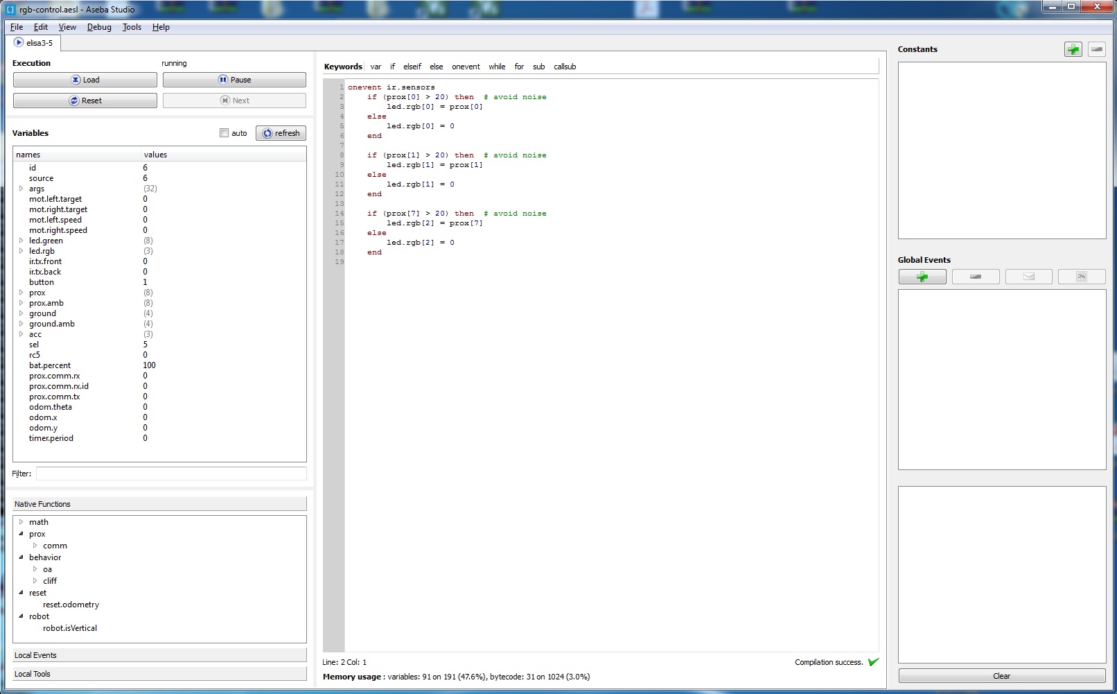
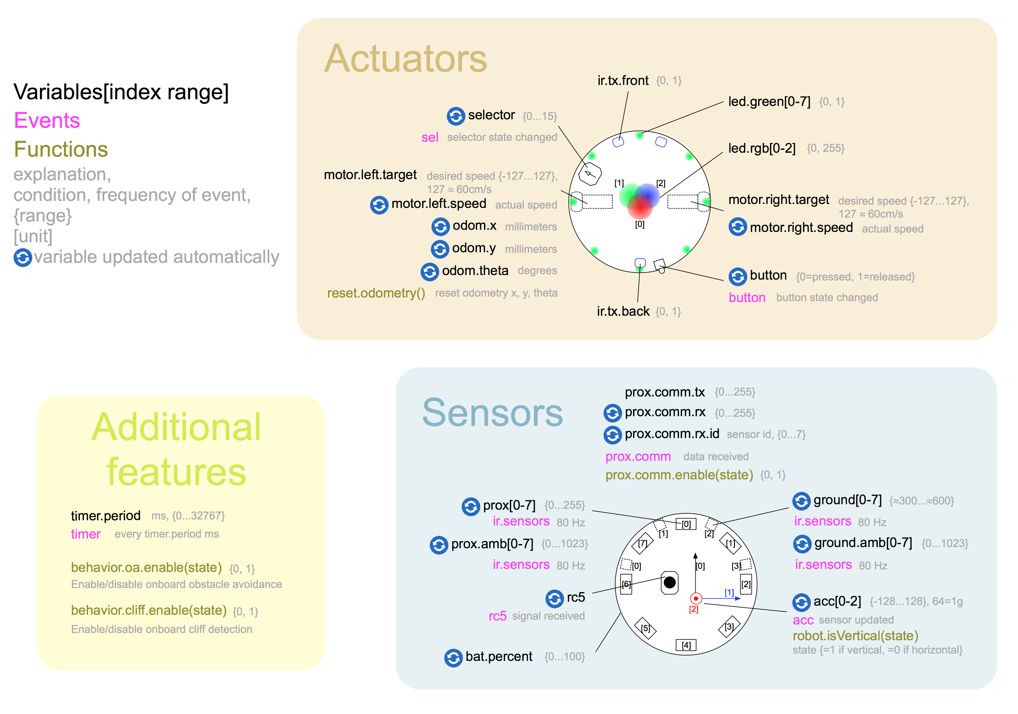