Elisa-3 and e-puck2 PC side development: Difference between pages
| Line 1: | Line 1: | ||
[{{fullurl:e-puck2}} e-puck2 main wiki]<br/> | |||
= | =Robot configuration= | ||
This section explains how to configure the robot based on the communication channel you will use for your developments, thus you need to read only one of the following sections, but it would be better if you spend a bit of time reading them all in order to have a full understanding of the available configurations. | |||
== | ==USB== | ||
The | The main microcontroller is initially programmed with a firmware that support USB communication.<br/> | ||
If the main microcontroller isn't programmed with the factory firmware or if you want to be sure to have the last firmware on the robot, you need to program it with the last factory firmware by referring to section [https://www.gctronic.com/doc/index.php?title=e-puck2#Firmware_update main microcontroller firmware update].<br/> | |||
The radio module can be programmed with either the <code>Bluetooth</code> or the <code>WiFi</code> firmware, both are compatible with USB communication: | |||
* Bluetooth: refer to section [https://www.gctronic.com/doc/index.php?title=e-puck2#Firmware_update_2 radio module firmware update] | |||
* WiFi: download the [https://projects.gctronic.com/epuck2/esp32-firmware-wifi_25.02.19_e2f4883.zip radio module wifi firmware (25.02.19)] and then refer to section [https://www.gctronic.com/doc/index.php?title=e-puck2#Firmware_update_2 radio module firmware update] | |||
When you want to interact with the robot from the computer you need to place the selector in position 8 to work with USB. <br/> | |||
Section [https://www.gctronic.com/doc/index.php?title=e-puck2#PC_interface PC interface] gives step by step instructions on how to connect the robot with the computer via USB.<br/> | |||
Once you tested the connection with the robot and the computer, you can start developing your own application by looking at the details behind the communication protocol. Both USB and Bluetooth communication channels use the same protocol called [https://www.gctronic.com/doc/index.php?title=e-puck2_PC_side_development#Bluetooth_and_USB advanced sercom v2], refer to section [https://www.gctronic.com/doc/index.php?title=e-puck2_PC_side_development#Bluetooth_and_USB_2 Communication protocol: BT and USB] for detailed information about this protocol.<br/> | |||
== | ==Bluetooth== | ||
The robot | The main microcontroller and radio module of the robot are initially programmed with firmwares that together support Bluetooth communication.<br/> | ||
If the main microcontroller and radio module aren't programmed with the factory firmware or if you want to be sure to have the last firmwares on the robot, you need to program them with the last factory firmwares: | |||
* for the main microcontroller, refer to section [https://www.gctronic.com/doc/index.php?title=e-puck2#Firmware_update main microcontroller firmware update] | |||
* for the radio module, refer to section [https://www.gctronic.com/doc/index.php?title=e-puck2#Firmware_update_2 radio module firmware update] | |||
When you want to interact with the robot from the computer you need to place the selector in position 3 if you want to work with Bluetooth. <br/> | |||
Section [https://www.gctronic.com/doc/index.php?title=e-puck2_PC_side_development#Connecting_to_the_Bluetooth Connecting to the Bluetooth] gives step by step instructions on how to accomplish your first Bluetooth connection with the robot.<br/> | |||
Once you tested the connection with the robot and the computer, you can start developing your own application by looking at the details behind the communication protocol. Both Bluetooth and USB communication channels use the same protocol called [https://www.gctronic.com/doc/index.php?title=e-puck2_PC_side_development#Bluetooth_and_USB advanced sercom v2], refer to section [https://www.gctronic.com/doc/index.php?title=e-puck2_PC_side_development#Bluetooth_and_USB Communication protocol: BT and USB] for detailed information about this protocol.<br/> | |||
==WiFi== | |||
For working with the WiFi, the main microcontroller must be programmed with the factory firmware and the radio module must be programmed with a dedicated firmware (not the factory one): | |||
* for the main microcontroller, refer to section [https://www.gctronic.com/doc/index.php?title=e-puck2#Firmware_update main microcontroller firmware update] | |||
* [https://projects.gctronic.com/epuck2/esp32-firmware-wifi_25.02.19_e2f4883.zip radio module wifi firmware (25.02.19)], for information on how to update the firmware refer to section [https://www.gctronic.com/doc/index.php?title=e-puck2#Firmware_update_2 radio module firmware update] | |||
Put the selector in position 15(F).<br/> | |||
Section [https://www.gctronic.com/doc/index.php?title=e-puck2_PC_side_development#Connecting_to_the_WiFi Connecting to the WiFi] gives step by step instructions on how to accomplish your first WiFi connection with the robot.<br/> | |||
The communication protocol is described in detail in the section [https://www.gctronic.com/doc/index.php?title=e-puck2_PC_side_development#WiFi_2 Communication protocol: WiFi].<br/> | |||
= | =Connecting to the Bluetooth= | ||
The factory firmware of the radio module creates 3 Bluetooth channels using the RFcomm protocol when the robot is paired with the computer: | |||
# Channel 1, GDB: port to connect with GDB if the programmer is in mode 1 or 3 (refer to chapter [https://www.gctronic.com/doc/index.php?title=e-puck2_programmer_development#Configuring_the_Programmer.27s_settings Configuring the Programmer's settings] for more information about these modes) | |||
# Channel 2, UART: port to connect to the UART port of the main processor | |||
# Channel 3, SPI: port to connect to the SPI port of the main processor (not yet implemented. Just do an echo for now) | |||
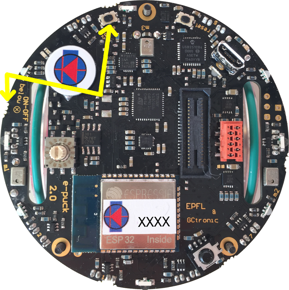
By default, the e-puck2 is not visible when you search for it in the Bluetooth utility of your computer.<br> | |||
'''To make it visible, it is necessary to hold the USER button (also labeled "esp32" on the electronic board) while turning on the robot with the ON/OFF button.'''<br> | |||
::<span class="plain links">[https://projects.gctronic.com/epuck2/wiki_images/e-puck2-bt-pair.png <img width=250 src="https://projects.gctronic.com/epuck2/wiki_images/e-puck2-bt-pair-small.png">]</span><br/> | |||
Then it will be discoverable and you will be able to pair with it.<br> | |||
Note that a prompt could ask you to confirm that the number written on the screen is the same on the e-puck. just ignore this and accept. Otherwise if you are asked for a pin insert 0000. | |||
== | ==Windows 7== | ||
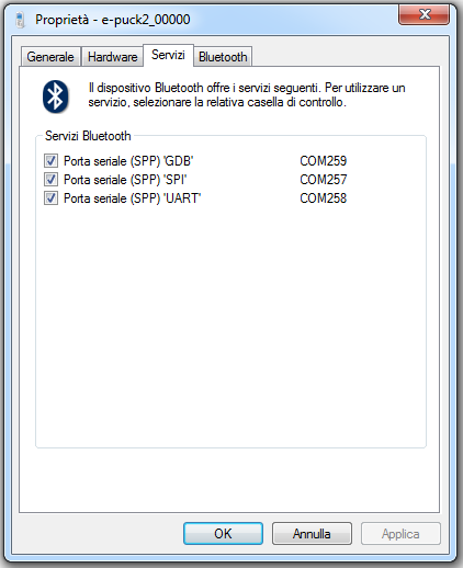
When you pair your computer with the e-puck2, 3 COM ports will be automatically created. | |||
< | To see which COM port corresponds to which channel you need to open the properties of the paired e-puck2 robot from <code>Bluetooth devices</code>. Then the ports and related channels are listed in the <code>Services</code> tab, as shown in the following figure:<br/> | ||
<span class="plain links">[https://projects.gctronic.com/epuck2/wiki_images/BT-connection-win7.png <img width=300 src="https://projects.gctronic.com/epuck2/wiki_images/BT-connection-win7.png">]</span> | |||
- | |||
--> | |||
== | ==Windows 10== | ||
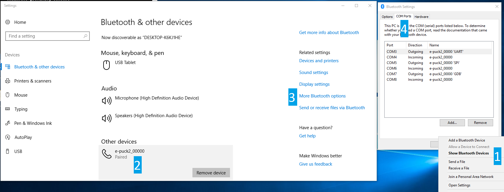
The | When you pair your computer with the e-puck2, 6 COM ports will be automatically created. The three ports you will use have <code>Outgoing</code> direction and are named <code>e_puck2_xxxxx-GDB</code>, <code>e_puck2_xxxxx-UART</code>, <code>e_puck2_xxxxx-SPI</code>. <code>xxxxx</code> is the ID number of your e-puck2.<br/> | ||
To see which COM port corresponds to which channel you need to: | |||
# open the Bluetooth devices manager | |||
# pair with the robot | |||
# click on <code>More Bluetooth options</code> | |||
# the ports and related channels are listed in the <code>COM Ports</code> tab, as shown in the following figure:<br/> | |||
:<span class="plain links">[https://projects.gctronic.com/epuck2/wiki_images/BT-connection-win10.png <img height=300 src="https://projects.gctronic.com/epuck2/wiki_images/BT-connection-win10.png">]</span> | |||
==Linux== | |||
Once paired with the Bluetooth manager, you need to create the port for communicating with the robot by issueing the command: <br/> | |||
<code>sudo rfcomm bind /dev/rfcomm0 MAC_ADDR 2</code><br/> | |||
The MAC address is visible from the Bluetooth manager. The parameter <code>2</code> indicates the channel, in this case a port for the <code>UART</code> channel is created. If you want to connect to another service you need to change this parameter accordingly (e.g. <code>1</code> for <code>GDB</code> and <code>3</code> for <code>SPI</code>). Now you can use <code>/dev/rfcomm0</code> to connect to the robot. | |||
==Mac== | |||
When you pair your computer with the e-puck2, 3 COM ports will be automatically created: <code>/dev/cu.e-puck2_xxxxx-GDB</code>, <code>/dev/cu.e-puck2_xxxxx-UART</code> and <code>/dev/cu.e-puck2_xxxxx-SPI</code>. xxxxx is the ID number of your e-puck2. | |||
==Testing the Bluetooth connection== | |||
You need to download the PC application provided in section [https://www.gctronic.com/doc/index.php?title=e-puck2#Available_executables PC interface: available executables].<br/> | |||
* | In the connection textfield you need to enter the UART channel port, for example: | ||
* | * Windows 7: <code>COM258</code> | ||
* Windows 10: <code>e_puck2_xxxxx-UART</code> | |||
* Linux: <code>/dev/rfcomm0</code> | |||
* Mac: <code>/dev/cu.e-puck2_xxxxx-UART</code> | |||
and then click <code>Connect</code>. <br/> | |||
You should start receiving sensors data and you can send commands to the robot.<br/> | |||
Alternatively you can also use a simple terminal program (e.g. <code>realterm</code> in Windows) instead of the PC application, then you can issue manually the commands to receive sensors data or for setting the actuators (once connected, type <code>h + ENTER</code> for a list of availables commands). | |||
==Python examples== | |||
* | Here are some basic Python 3 examples that show how to get data from the robot through Bluetooth using the commands available with the [https://www.gctronic.com/doc/index.php?title=e-puck2_PC_side_development#Bluetooth_and_USB advanced sercom v2]: | ||
* | * [https://projects.gctronic.com/epuck2/printhelp.py printhelp.py]: print the list of commands available in the [https://www.gctronic.com/doc/index.php?title=e-puck2_PC_side_development#Bluetooth_and_USB advanced sercom v2] | ||
* | * [https://projects.gctronic.com/epuck2/getprox.py getprox.py]: print the values of the proximity sensors | ||
* [https://projects.gctronic.com/epuck2/complete.py complete.py]: set all the actuators and get all the sensors data printing their values on the screen | |||
* [https://projects.gctronic.com/epuck2/getimage.py getimage.py]: request an image and save it to disk | |||
* [https://projects.gctronic.com/epuck2/getmagnetometer.py getmagnetometer.py]: enable the magnetometer and print its values | |||
In all the examples you need to set the correct Bluetooth serial port related to the robot. | |||
===Connecting to multiple robots=== | |||
Here is a simple Python 3 script [https://projects.gctronic.com/epuck2/multi-robot.py multi-robot.py] that open a connection with 2 robots and exchange data with them using the [https://www.gctronic.com/doc/index.php/Advanced_sercom_protocol advanced sercom protocol]. This example can be extended to connect to more than 2 robots. | |||
== | ===Automotive=== | ||
Initial project in which some robots navigate a city trying to handle the crossroads using only the onboard sensors. You can download the Python 3 script from [https://projects.gctronic.com/epuck2/epuck2_automotive.py epuck2_automotive.py]. <br/> | |||
Here is a video of this demo: {{#ev:youtube|N39EDy1qt4o}} | |||
# | |||
==C++ remote library== | |||
A remote control library implemented in C++ is available to control the e-puck2 robot via a Bluetooth connection from the computer.<br/> | |||
The remote control library is multiplatform and uses only standard C++ libraries.<br/> | |||
You can download the library with the command <code>git clone https://github.com/e-puck2/e-puck2_cpp_remote_library</code>.<br/> | |||
A simple example showing how to use the library is also available; you can download it with the command <code>git clone https://github.com/e-puck2/e-puck2_cpp_remote_example</code>.<br/> | |||
Before building the example you need to build the library. Then when building the example, make sure that both the library and the example are in the same directory, that is you must end up with the following directory tree:<br> | |||
: e-puck2_projects | |||
::|_ e-puck2_cpp_remote_library | |||
::|_ e-puck2_cpp_remote_example | |||
The complete API reference is available in the following link [https://projects.gctronic.com/epuck2/e-puck2_cpp_remote_library_api_reference_rev3ac41e3.pdf e-puck2_cpp_remote_library_api_reference.pdf]. | |||
= | =Connecting to the WiFi= | ||
The WiFi channel is used to communicate with robot faster than with Bluetooth. At the moment a QQVGA (160x120) color image is transferred to the computer together with the sensors values at about 10 Hz; of course the robot is also able to receive commands from the computer.<br/> | |||
In order to communicate with the robot through WiFi, first you need to configure the network parameters on the robot by connecting directly to it, since the robot is initially configured in access point mode, as explained in the following section. Once the configuration is saved on the robot, it will then connect automatically to the network and you can connect to it. | |||
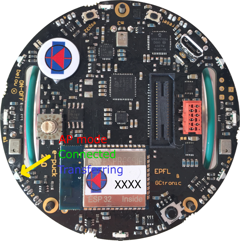
The LED2 is used to indicate the state of the WiFi connection: | |||
* red indicates that the robot is in ''access point mode'' (waiting for configuration) | |||
* green indicates that the robot is connected to a network and has received an IP address | |||
* | * blue (toggling) indicates that the robot is transferring the image to the computer | ||
* | * off when the robot cannot connect to the saved configuration | ||
* | ::<span class="plain links">[https://projects.gctronic.com/epuck2/wiki_images/e-puck2-wifi-led.png <img width=250 src="https://projects.gctronic.com/epuck2/wiki_images/e-puck2-wifi-led-small.png">]</span><br/> | ||
== | ==Network configuration== | ||
If there is no WiFi configuration saved in flash, then the robot will be in ''access point mode'' in order to let the user connect to it and setup a WiFi connection. The LED2 is red. | |||
The access point SSID will be <code>e-puck2_0XXXX</code> where <code>XXXX</code> is the id of the robot; the password to connect to the access point is <code>e-puck2robot</code>.<br/> | |||
You can use a phone, a tablet or a computer to connect to the robot's WiFi and then you need to open a browser and insert the address <code>192.168.1.1</code>. The available networks are scanned automatically and listed in the browser page as shown in ''figure 1''. Choose the WiFi signal you want the robot to establish a conection with from the web generated list, and enter the related password; if the password is correct you'll get a message saying that the connection is established as shown in ''figure 2''. After pressing <code>OK</code> you will be redirected to the main page showing the network to which you're connected and the others available nearby as shown in ''figure 3''. If you press on the connected network, then you can see your IP address as shown in ''figure 4''; <b>take note of the address since it will be needed later</b>.<br/> | |||
==== | <span class="plainlinks"> | ||
<table> | |||
<tr> | |||
<td align="center">[1]</td> | |||
<td align="center">[2]</td> | |||
<td align="center">[3]</td> | |||
<td align="center">[4]</td> | |||
</tr> | |||
<tr> | |||
<td>[https://projects.gctronic.com/epuck2/wiki_images/esp32-wifi-setup1.png <img width=150 src="https://projects.gctronic.com/epuck2/wiki_images/esp32-wifi-setup1.png">]</td> | |||
<td>[https://projects.gctronic.com/epuck2/wiki_images/esp32-wifi-setup2.png <img width=150 src="https://projects.gctronic.com/epuck2/wiki_images/esp32-wifi-setup2.png">]</td> | |||
<td>[https://projects.gctronic.com/epuck2/wiki_images/esp32-wifi-setup3.png <img width=150 src="https://projects.gctronic.com/epuck2/wiki_images/esp32-wifi-setup3.png">]</td> | |||
<td>[https://projects.gctronic.com/epuck2/wiki_images/esp32-wifi-setup4.png <img width=150 src="https://projects.gctronic.com/epuck2/wiki_images/esp32-wifi-setup4.png">]</td> | |||
</tr> | |||
</table> | |||
</span><br/> | |||
Now the configuration is saved in flash, this means that when the robot is turned on it will read this configuration and try to establish a connection automatically.<br/> | |||
Remember that you need to power cycle the robot at least once for the new configuration to be active.<br/> | |||
Once the connection is established, the LED2 will be green.<br/> | |||
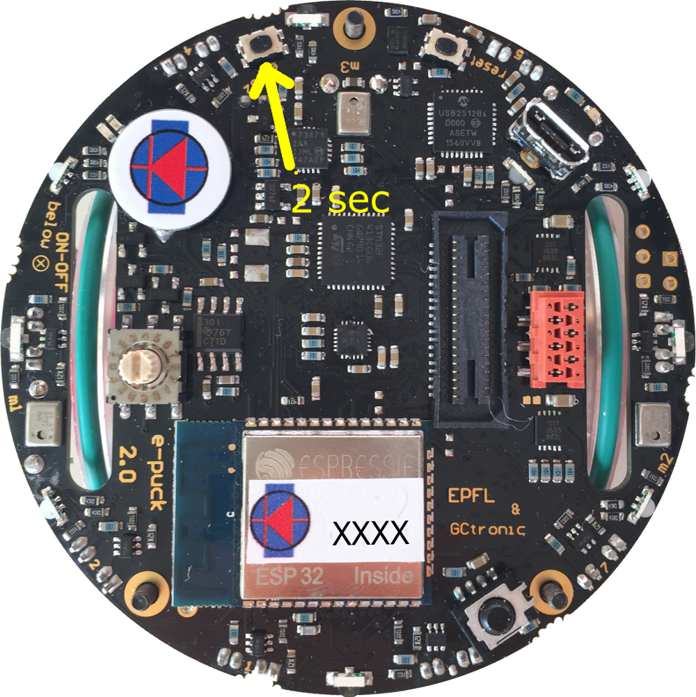
In order to reset the current configuration you need to press the user button for 2 seconds (the LED2 red will turn on), then you need to power cycle the robot to enter ''access point mode''. | |||
::<span class="plain links">[https://projects.gctronic.com/epuck2/wiki_images/e-puck2-wifi-reset.png <img width=250 src="https://projects.gctronic.com/epuck2/wiki_images/e-puck2-wifi-reset-small.png">]</span><br/> | |||
==Finding the IP address== | |||
Often the IP address assigned to the robot will remain the same when connecting to the same network, so if you took note of the IP address in section [https://www.gctronic.com/doc/index.php?title=e-puck2#Network_configuration Network configuration] you're ready to go to the next section. <br/> | |||
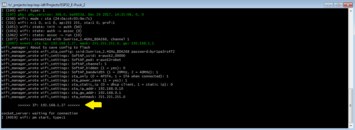
Otherwise you need to connect the robot to the computer with the USB cable, open a terminal and connect to the port labeled <code>Serial Monitor</code> (see chapter [https://www.gctronic.com/doc/index.php?title=e-puck2#Finding_the_USB_serial_ports_used Finding the USB serial ports used]). Then power cycle the robot and the IP address will be shown in the terminal (together with others informations), as illustrated in the following figure:<br/> | |||
<span class="plain links">[https://projects.gctronic.com/epuck2/wiki_images/esp32-wifi-setup5.png <img width=500 src="https://projects.gctronic.com/epuck2/wiki_images/esp32-wifi-setup5.png">]</span> | |||
==Testing the WiFi connection== | |||
A dedicated WiFi version of the PC application was developed to communicate with the robot through TCP protocol. You can download the executable from one of the following links: | |||
* [https://projects.gctronic.com/epuck2/monitor_wifi_27dddd4.zip Windows executable - WiFi] | |||
* [https://projects.gctronic.com/epuck2/monitor_mac_wifi.zip Max OS X executable - WiFi] | |||
* [https://projects.gctronic.com/epuck2/monitor_wifi_linux64bit_27dddd4.tar.gz Ubuntu 14.04 (or later) - 64 bit] | |||
If you are interested to the source code, you can download it with the command <code>git clone -b wifi --recursive https://github.com/e-puck2/monitor.git</code><br/> | |||
Run the PC application, insert the IP address of the robot in the connection textfield and then click on the <code>Connect</code> button. You should start receiving sensors data and you can send commands to the robot. The LED2 blue will toggle.<br/> | |||
==Web server== | |||
When the robot is in ''access point mode'' you can have access to a web page showing the camera image and some buttons that you can use to move the robot; it is a basic example that you can use as a starting point to develop your own web browser interface.<br/> | |||
You can use a phone, a tablet or a computer to connect to the robot's WiFi and then you need to open a browser and insert the address <code>192.168.1.1/monitor.html</code>. | |||
=== | ==Python examples== | ||
===Connecting to multiple robots=== | |||
A simple Python 3 script was developed as a starting point to open a connection with multiple robots and exchange data with them using the [https://www.gctronic.com/doc/index.php?title=e-puck2_PC_side_development#WiFi_2 WiFi communication protocol]. The demo was tested with 10 robots but can be easily extended to connect to more robots.<br/> | |||
You can download the script with the command <code>git clone https://github.com/e-puck2/e-puck2_python_wifi_multi.git</code>. The code was tested to work with Python 3.x. | |||
= | =Communication protocol= | ||
This section is the hardest part to understand. It outlines all the details about the communication protocols that you'll need to implement in order to communicate with the robot form the computer. So spend a bit of time reading and re-reading this section in order to grasp completely all the details. | |||
=== | ==Bluetooth and USB== | ||
<span class=" | The communication protocol is based on the [https://www.gctronic.com/doc/index.php/Advanced_sercom_protocol advanced sercom protocol], used with the e-puck1.x robot. The <code>advanced sercom v2</code> includes all the commands available in the <code>advanced sercom</code> protocol and add some additional commands to handle the new features of the e-puck2 robot. In particular here are the new commands: | ||
{| border="1" cellpadding="10" cellspacing="0" | |||
!Command | |||
!Description | |||
!Return value / set value | |||
|- | |||
|<code>-0x08</code> | |||
|Get all sensors | |||
|<span class="plain links">[https://projects.gctronic.com/epuck2/wiki_images/packet-format-robot-to-pc.jpg <img width=1150 src="https://projects.gctronic.com/epuck2/wiki_images/packet-format-robot-to-pc.jpg">]</span> | |||
see section [https://www.gctronic.com/doc/index.php?title=e-puck2_PC_side_development#WiFi_2 Communication protocol: WiFi] for the content description | |||
|- | |||
|<code>-0x09</code> | |||
|Set all actuators | |||
|<span class="plain links">[https://projects.gctronic.com/epuck2/wiki_images/packet-format-pc-to-robot-bt.jpg <img width=600 src="https://projects.gctronic.com/epuck2/wiki_images/packet-format-pc-to-robot-bt.jpg">]</span> | |||
see section [https://www.gctronic.com/doc/index.php?title=e-puck2_PC_side_development#WiFi_2 Communication protocol: WiFi] for the content description | |||
|- | |||
|<code>-0x0A</code> | |||
|Set RGB LEDs, values from 0 (off) to 100 (completely on) | |||
|<code>[LED2_red][LED2_green][LED2_blue][LED4_red][LED4_green][LED4_blue][LED6_red][LED6_green][LED6_blue][LED8_red][LED8_green][LED8_blue]</code> | |||
|- | |||
|<code>-0x0B</code> | |||
|Get button state: 0 = not pressed, 1 = pressed | |||
|<code>[STATE]</code> | |||
|- | |||
|<code>-0x0C</code> | |||
|Get all 4 microphones volumes | |||
|<code>[MIC0_LSB][MIC0_MSB][MIC1_LSB][MIC1_MSB][MIC2_LSB][MIC2_MSB][MIC3_LSB][MIC3_MSB]</code> | |||
|- | |||
|<code>-0x0D</code> | |||
|Get distance from ToF sensor (millimeters) | |||
|<code>[DIST_LSB][DIST_MSB]</code> | |||
|- | |||
|<code>-0x0E</code> | |||
|Get SD state: 0 = micro sd not connected, 1 = micro sd connected | |||
|<code>[STATE]</code> | |||
|- | |||
|<code>-0x0F</code> | |||
|Enable/disable magnetometer: 0 = disable, 1 = enable | |||
|<code>[STATE]</code> | |||
|- | |||
|<code>-0x10</code> | |||
|Set proximity state: 0 = disable proximity sampling, 1 = enable fast proximity sampling (100 hz), 2 = enable slow proximity sampling (20 hz) | |||
|<code>[STATE]</code> | |||
|- | |||
|<code>-0x0F</code> | |||
|Enable/disable magnetometer: 0 = disable, 1 = enable | |||
|<code>[STATE]</code> | |||
|} | |||
==WiFi== | |||
The communication is based on TCP; the robot create a TCP server and wait for a connection.<br/> | |||
Each packet is identified by an ID (1 byte). The following IDs are used to send data from the robot to the computer: | |||
* 0x00 = reserved | |||
* 0x01 = QQVGA color image packet (only the first segment includes this id); packet size (without id) = 38400 bytes; image format = RGB565 | |||
* 0x02 = sensors packet; packet size (without id) = 104 bytes; the format of the returned values are based on the [https://www.gctronic.com/doc/index.php/Advanced_sercom_protocol advanced sercom protocol] and are compatible with e-puck1.x: | |||
=== | :<span class="plain links">[https://projects.gctronic.com/epuck2/wiki_images/packet-format-robot-to-pc.jpg <img width=1150 src="https://projects.gctronic.com/epuck2/wiki_images/packet-format-robot-to-pc.jpg">]</span><br/> | ||
:*Acc: raw axes values (0=X LSB, 1=X MSB, 2=Y LSB, 3=Y MSB, 4=Z LSB, 5=Z MSB), between -1500 and 1500, resolution is +-2g | |||
:*Acceleration expressed in float: acceleration magnitude <img width=70 src="https://projects.gctronic.com/epuck2/wiki_images/3dvector-magnitude.png">, between 0.0 and about 2600.0 (~3.46 g) | |||
:*Orientation expressed in float: between 0.0 and 360.0 degrees <table><tr><td align="center">0.0 deg</td><td align="center">90.0 deg</td><td align="center">180 deg</td><td align="center">270 deg</td></tr><tr><td><img width=80 src="https://projects.gctronic.com/epuck2/wiki_images/orientation0.png"></td><td><img width=80 src="https://projects.gctronic.com/epuck2/wiki_images/orientation90.png"></td><td><img width=80 src="https://projects.gctronic.com/epuck2/wiki_images/orientation180.png"></td><td><img width=80 src="https://projects.gctronic.com/epuck2/wiki_images/orientation270.png"></td></tr></table> | |||
= | :*Inclination expressed in float: between 0.0 and 90.0 degrees (when tilted in any direction)<table><tr><td align="center">0.0 deg</td><td align="center">90.0 deg</td></tr><tr><td><img width=80 src="https://projects.gctronic.com/epuck2/wiki_images/inclination0.png"></td><td><img width=80 src="https://projects.gctronic.com/epuck2/wiki_images/inclination90.png"></td></tr></table> | ||
:*Gyro: raw axes values (0=X LSB, 1=X MSB, 2=Y LSB, 3=Y MSB, 4=Z LSB, 5=Z MSB), between -32768 and 32767, range is +-250dps | |||
< | :*Magnetometer: raw axes values expressed in float, range is +-4912.0 uT (magnetic flux density expressed in micro Tesla) | ||
:*Temp: temperature given in Celsius degrees | |||
:*IR proximity (0=IR_0 LSB, 1=IR_0 MSB, ...): between 0 (no objects detected) and 4095 (object near the sensor) | |||
:*IR ambient (0=IR_0 LSB, 1=IR_0 MSB, ...): between 0 (strong light) and 4095 (dark) | |||
:*ToF distance: distance given in millimeters | |||
:*Mic volume (0=MIC_0 LSB, 1=MIC_0 MSB, ...): between 0 and 4095 | |||
:*Motors steps: 1000 steps per wheel revolution | |||
:*Battery: | |||
:*uSD state: 1 if the micro sd is present and can be read/write, 0 otherwise | |||
:*TV remote data: RC5 protocol | |||
:*Selector position: between 0 and 15 | |||
:*Ground proximity (0=GROUND_0 LSB, 1=GROUND_0 MSB, ...): between 0 (no surface at all or not reflective surface e.g. black) and 1023 (very reflective surface e.g. white) | |||
:*Ground ambient (0=GROUND_0 LSB, 1=GROUND_0 MSB, ...): between 0 (strong light) and 1023 (dark) | |||
:*Button state: 1 button pressed, 0 button released | |||
* 0x03 = empty packet (only id is sent); this is used as an acknowledgment for the commands packet when no sensors and no image is requested | |||
The following IDs are used to send data from the computer to the robot: | |||
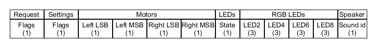
* 0x80 = commands packet; packet size (without id) = 20 bytes: | |||
:<span class="plain links">[https://projects.gctronic.com/epuck2/wiki_images/packet-format-pc-to-robot.jpg <img width=600 src="https://projects.gctronic.com/epuck2/wiki_images/packet-format-pc-to-robot.jpg">]</span><br/> | |||
:*request: | |||
:** bit0: 0=stop image stream; 1=start image stream | |||
:** bit1: 0=stop sensors stream; 1=start sensors stream | |||
:*settings: | |||
:** bit0: 1=calibrate IR proximity sensors | |||
:** bit1: 0=disable onboard obstacle avoidance; 1=enable onboard obstacle avoidance (not implemented yet) | |||
:** bit2: 0=set motors speed; 1=set motors steps (position) | |||
:*left and right: when bit2 of <code>settings</code> field is <code>0</code>, then this is the desired motors speed (-1000..1000); when <code>1</code> then this is the value that will be set as motors position (steps) | |||
:*LEDs: 0=off; 1=on | |||
:** bit0: 0=LED1 off; 1=LED1 on | |||
:** bit1: 0=LED3 off; 1=LED3 on | |||
:** bit2: 0=LED5 off; 1=LED5 on | |||
:** bit3: 0=LED7 off; 1=LED7 on | |||
:** bit4: 0=body LED off; 1=body LED on | |||
:** bit5: 0=front LED off; 1=front LED on | |||
:*RGB LEDs: for each LED, it is specified in sequence the value of red, green and blue (0...100) | |||
:* sound id: 0x01=MARIO, 0x02=UNDERWOLRD, 0x04=STARWARS, 0x08=4KHz, 0x10=10KHz, 0x20=stop sound | |||
For example to receive the camera image (stream) the following steps need to be followed:<br/> | |||
1) connect to the robot through TCP<br/> | |||
2) send the command packet: | |||
:{| border="1" | |||
|0x80 | |||
|0x01 | |||
|0x00 | |||
|0x00 | |||
|0x00 | |||
|0x00 | |||
|0x00 | |||
|0x00 | |||
|0x00 | |||
|0x00 | |||
|0x00 | |||
|0x00 | |||
|0x00 | |||
|0x00 | |||
|0x00 | |||
|0x00 | |||
|0x00 | |||
|0x00 | |||
|0x00 | |||
|0x00 | |||
|0x00 | |||
|} | |||
3) read the ID (1 byte) and the QQVGA color image pakcet (38400 bytes)<br/> | |||
4) go to step 3 | |||
= | =Webots= | ||
1. Download the last version of [https://cyberbotics.com/ Webots] for your platform and install it.<br/> | |||
2. Program the robot with the [https://www.gctronic.com/doc/index.php?title=e-puck2#WiFi_firmware WiFi firmware] and put the selector in position 15(F). Connect the robot to your WiFi network.<br/> | |||
3. Open the example world you can find in the Webots installation directory <code>Webots\projects\robots\gctronic\e-puck\worlds\e-puck2.wbt</code>.<br/> | |||
4. Double click the robot, a new small window will appear: insert the IP address of the robot and click connect.<br/> | |||
:<span class="plainlinks">[https://www.gctronic.com/doc/images/epuck2-webots.png <img width=450 src="https://www.gctronic.com/doc/images/epuck2-webots.png">]</span> | |||
5. Now you can start the demo, the robot will be remote controlled.<br/> | |||
For more information have a look at the [https://cyberbotics.com/doc/guide/epuck e-puck Webots guide]. | |||
=ROS= | |||
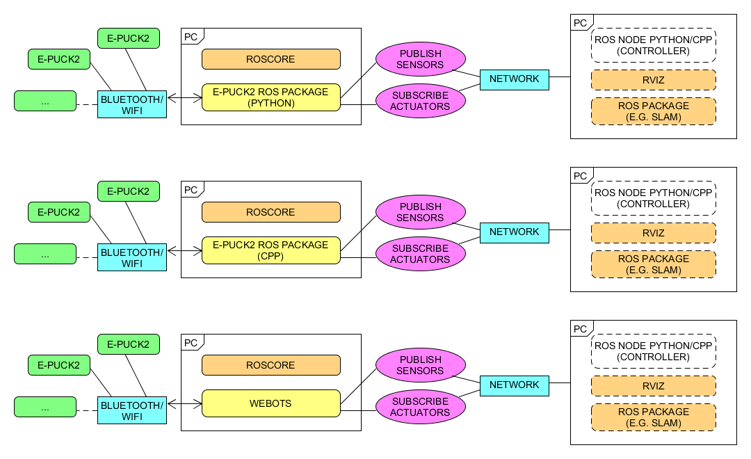
This chapter explains how to use ROS with the e-puck2 robots by connecting them via Bluetooth or WiFi to the computer that runs the ROS nodes. Basically all the sensors are exposed to ROS and you can also send commands back to the robot through ROS. Both Pyhton and cpp versions are implemented to give the user the possibility to choose its preferred programming language. Here is a general schema:<br/> | |||
<span class="plainlinks">[https://www.gctronic.com/doc/images/epuck2-ros-schema.png <img width=450 src="https://www.gctronic.com/doc/images/epuck2-ros-schema-small.png">]</span> | |||
''<font size="2">Click to enlarge</font>''<br/> | |||
: | |||
<span class="plainlinks">[https://www.gctronic.com/doc/images/ | |||
First of all you need to install and configure ROS, refer to [https://wiki.ros.org/Distributions https://wiki.ros.org/Distributions] for more informations. <font style="color:red"> This tutorial is based on ROS Kinetic</font>. The same instructions are working with ROS Noetic, beware to use <code>noetic</code> instead of <code>kinetic</code> when installing the packages. | |||
Starting from the work done with the e-puck1 (see [https://www.gctronic.com/doc/index.php?title=E-Puck#ROS E-Puck ROS]), we updated the code in order to support the e-puck2 robot. | |||
== | ==Initial configuration== | ||
The | The following steps need to be done only once, after installing ROS: | ||
:1. If not already done, create a catkin workspace, refer to [https://wiki.ros.org/catkin/Tutorials/create_a_workspace https://wiki.ros.org/catkin/Tutorials/create_a_workspace]. Basically you need to issue the following commands: | |||
<pre> mkdir -p ~/catkin_ws/src | |||
cd ~/catkin_ws/src | |||
catkin_init_workspace | |||
cd ~/catkin_ws/ | |||
catkin_make | |||
source devel/setup.bash </pre> | |||
:2. You will need to add the line <code>source ~/catkin_ws/devel/setup.bash</code> to your <tt>.bashrc</tt> in order to automatically have access to the ROS commands when the system is started | |||
:3. Move to <code>~/catkin_ws/src</code> and clone the ROS e-puck2 driver repo: | |||
:* if you are working with Python (only Bluetooth communication supported at the moment): <code>git clone -b e-puck2 https://github.com/gctronic/epuck_driver</code> | |||
:* if you are working with cpp: | |||
:** Bluetooth communication: <code>git clone -b e-puck2 https://github.com/gctronic/epuck_driver_cpp</code> | |||
:** WiFi communication: <code>git clone -b e-puck2_wifi https://github.com/gctronic/epuck_driver_cpp</code> | |||
:4. Install the dependencies: | |||
:* ROS: | |||
:** [https://wiki.ros.org/gmapping gmapping (SLAM)] package: <code>sudo apt-get install ros-kinetic-gmapping</code> | |||
:** [https://wiki.ros.org/rviz_imu_plugin Rviz IMU plugin] package: <code>sudo apt-get install ros-kinetic-rviz-imu-plugin</code> | |||
:* Python: | |||
:** The ROS e-puck2 driver is based on the e-puck2 Python library that requires some dependencies: | |||
:*** install the Python setup tools: <code>sudo apt-get install python-setuptools</code> | |||
:*** install the Python image library: <code>sudo apt-get install python-imaging</code> | |||
:*** install pybluez version 0.22: <code>sudo pip install pybluez==0.22</code> | |||
:**** install pybluez dependencies: <code>sudo apt-get install libbluetooth-dev</code> | |||
:*** install OpenCV: <code>sudo apt-get install python3-opencv</code> | |||
:* cpp: | |||
:** install the library used to communicate with Bluetooth: <code>sudo apt-get install libbluetooth-dev</code> | |||
:** install OpenCV: <code>sudo apt-get install libopencv-dev</code> | |||
:*** if you are working with OpenCV 4, then you need to change the header include from <code>#include <opencv/cv.h></code> to <code>#include <opencv2/opencv.hpp></code> | |||
:5. Open a terminal and go to the catkin workspace directory (<tt>~/catkin_ws</tt>) and issue the command <code>catkin_make</code>, there shouldn't be errors | |||
:6. Program the e-puck2 robot with the [https://www.gctronic.com/doc/index.php?title=e-puck2#Factory_firmware factory firmware] and put the selector in position 3 for Bluetooth communication or in position 15(F) for WiFi Communication | |||
:7. Program the radio module with the correct firmware: | |||
:* Bluetooth communication: use the [https://www.gctronic.com/doc/index.php?title=e-puck2#Factory_firmware_2 factory firmware] | |||
:* WiFi communication: use the [https://www.gctronic.com/doc/index.php?title=e-puck2#WiFi_firmware WiFi firmware] | |||
==Running the Python ROS node== | |||
< | First of all get the last version of the ROS e-puck2 driver from github. Move to <code>~/catkin_ws/src</code> and issue: <code>git clone -b e-puck2 https://github.com/gctronic/epuck_driver</code>. <br/> | ||
Then build the driver by opening a terminal and issueing the command <code>catkin_make</code> from within the catkin workspace directory (e.g. ~/catkin_ws).<br/> | |||
Moreover make sure the node is marked as executable by opening a terminal and issueing the following command from within the catkin workspace directory (e.g. ~/catkin_ws): <code>chmod +x ./src/epuck_driver/scripts/epuck2_driver.py</code>. <br/> | |||
Before actually starting the e-puck2 node you need to configure the e-puck2 robot as Bluetooth device in the system, refer to section [https://www.gctronic.com/doc/index.php?title=e-puck2_PC_side_development#Connecting_to_the_Bluetooth Connecting to the Bluetooth].<br/> | |||
Once the robot is paired with the computer, you need to take note of its MAC address (this will be needed when launching the ROS node). To know the MAC address of a paired robot, go to <tt>System Settings</tt>, <tt>Bluetooth</tt> and select the robot; once selected you'll see in the right side the related MAC address. | |||
First thing to do before launching the script file is running the <tt>roscore</tt>, open another terminal tab and issue the command <tt>roscore</tt>. | |||
Now you can finally start the e-puck2 ROS node, for this purposes there is a launch script (based on [https://wiki.ros.org/roslaunch roslaunch]).<br/> | |||
Open a terminal and issue the following command: <code>roslaunch epuck_driver epuck2_controller.launch epuck2_address:='B4:E6:2D:EB:9C:4F'</code>.<br/> | |||
<tt>B4:E6:2D:EB:9C:4F</tt> is the e-puck2 Bluetooth MAC address that need to be changed accordingly to your robot. | |||
If all is going well you'll see the robot make a blink meaning it is connected and ready to exchange data and [https://wiki.ros.org/rviz/UserGuide rviz] will be opened showing the informations gathered from the topics published by the e-puck2 driver node. | |||
The | The launch script is configured also to run the [https://wiki.ros.org/gmapping gmapping (SLAM)] node that let the robot construct a map of the environment; the map is visualized in real-time directly in the rviz window. The gmapping package provides laser-based SLAM (Simultaneous Localization and Mapping) and since the e-puck2 has no laser sensor, the information from the 6 proximity sensors on the front side of the robot are interpolated to get 19 laser scan points. | ||
==== | The following figures show all the topics published by the e-puck2 driver node (left) and the <code>rviz</code> interface (right): <br/> | ||
<span class="plainlinks">[https://projects.gctronic.com/epuck2/wiki_images/e-puck2_topics.png <img width=200 src="https://projects.gctronic.com/epuck2/wiki_images/e-puck2_topics_small.png">]</span> | |||
''<font size="2">Click to enlarge</font>'' | |||
<span class="plainlinks">[https://projects.gctronic.com/epuck2/wiki_images/e-puck2-rviz.png <img width=400 src="https://projects.gctronic.com/epuck2/wiki_images/e-puck2-rviz_small.png">]</span> | |||
''<font size="2">Click to enlarge</font>''<br/> | |||
==Running the cpp ROS node== | |||
the | There is a small difference at the moment between the Bluetooth and WiFi versions of the ROS node: the WiFi ROS node supports also the publication of the magnetometer data. | ||
===Bluetooth=== | |||
First of all get the last version of the ROS e-puck2 driver from github. Move to <code>~/catkin_ws/src</code> and issue: <code>git clone -b e-puck2 https://github.com/gctronic/epuck_driver_cpp</code>. <br/> | |||
Then build the driver by opening a terminal and issueing the command <code>catkin_make</code> from within the catkin workspace directory (e.g. ~/catkin_ws).<br/> | |||
Before actually starting the e-puck2 node you need to configure the e-puck2 robot as Bluetooth device in the system, refer to section [https://www.gctronic.com/doc/index.php?title=e-puck2_PC_side_development#Connecting_to_the_Bluetooth Connecting to the Bluetooth].<br/> | |||
Once the robot is paired with the computer, you need to take note of its MAC address (this will be needed when launching the ROS node). To know the MAC address of a paired robot, go to <tt>System Settings</tt>, <tt>Bluetooth</tt> and select the robot; once selected you'll see in the right side the related MAC address. | |||
First thing to do before launching the script file is running the <tt>roscore</tt>, open another terminal tab and issue the command <tt>roscore</tt>. | |||
Now you can finally start the e-puck2 ROS node, for this purposes there is a launch script (based on [https://wiki.ros.org/roslaunch roslaunch]).<br/> | |||
Open a terminal and issue the following command: <code>roslaunch epuck_driver_cpp epuck2_controller.launch epuck2_address:='B4:E6:2D:EB:9C:4F'</code>.<br/> | |||
<tt>B4:E6:2D:EB:9C:4F</tt> is the e-puck2 Bluetooth MAC address that need to be changed accordingly to your robot. | |||
If all is going well the robot will be ready to exchange data and [https://wiki.ros.org/rviz/UserGuide rviz] will be opened showing the informations gathered from the topics published by the e-puck2 driver node. | |||
The launch script is configured also to run the [https://wiki.ros.org/gmapping gmapping (SLAM)] node that let the robot construct a map of the environment; the map is visualized in real-time directly in the rviz window. The gmapping package provides laser-based SLAM (Simultaneous Localization and Mapping) and since the e-puck2 has no laser sensor, the information from the 6 proximity sensors on the front side of the robot are interpolated to get 19 laser scan points. | |||
===WiFi=== | |||
First of all get the last version of the ROS e-puck2 driver from github. Move to <code>~/catkin_ws/src</code> and issue: <code>git clone -b e-puck2_wifi https://github.com/gctronic/epuck_driver_cpp</code>. <br/> | |||
Then build the driver by opening a terminal and issueing the command <code>catkin_make</code> from within the catkin workspace directory (e.g. ~/catkin_ws).<br/> | |||
Before actually starting the e-puck2 node you need to connect the e-puck2 robot to your WiFi network, refer to section [https://www.gctronic.com/doc/index.php?title=e-puck2_PC_side_development#Connecting_to_the_WiFi Connecting to the WiFi].<br/> | |||
First thing to do before launching the script file is running the <tt>roscore</tt>, open another terminal tab and issue the command <tt>roscore</tt>. | |||
Now you can finally start the e-puck2 ROS node, for this purposes there is a launch script (based on [https://wiki.ros.org/roslaunch roslaunch]).<br/> | |||
Open a terminal and issue the following command: <code>roslaunch epuck_driver_cpp epuck2_controller.launch epuck2_address:='192.168.1.20'</code>.<br/> | |||
<tt>192.168.1.20</tt> is the e-puck2 IP address that need to be changed accordingly to your robot. | |||
If all is going well the robot will be ready to exchange data and [https://wiki.ros.org/rviz/UserGuide rviz] will be opened showing the informations gathered from the topics published by the e-puck2 driver node. | |||
The launch script is configured also to run the [https://wiki.ros.org/gmapping gmapping (SLAM)] node that let the robot construct a map of the environment; the map is visualized in real-time directly in the rviz window. The gmapping package provides laser-based SLAM (Simultaneous Localization and Mapping) and since the e-puck2 has no laser sensor, the information from the 6 proximity sensors on the front side of the robot are interpolated to get 19 laser scan points. | |||
The | |||
The | The refresh rate of the topics is about 11 Hz when the camera image is enabled (see [https://projects.gctronic.com/epuck2/wiki_images/e-puck2_topics_wifi_refresh_camon.pdf e-puck2_topics_wifi_refresh_camon.pdf]) and about 50 Hz when the camera image is disabled (see [https://projects.gctronic.com/epuck2/wiki_images/e-puck2_topics_wifi_refresh_camoff.pdf e-puck2_topics_wifi_refresh_camoff.pdf]). The same graphs can be created using the command <code>rosrun tf view_frames</code>. | ||
The following | The following figure shows all the topics published by the e-puck2 WiFi ROS node. The same graph can be created using the command <code>rqt_graph</code>. <br/> | ||
<span class="plainlinks">[https://projects.gctronic.com/epuck2/wiki_images/e-puck2_topics_wifi.png <img width=200 src="https://projects.gctronic.com/epuck2/wiki_images/e-puck2_topics_wifi.png">]</span> | |||
''<font size="2">Click to enlarge</font>'' | |||
== | ==Move the robot== | ||
You have some options to move the robot.<br/> | |||
The first one is to use the <code>rviz</code> interface: in the bottom left side of the interface there is a <code>Teleop</code> panel containing an ''interactive square'' meant to be used with differential drive robots. By clicking in this square you'll move the robot, for instance by clicking on the top-right section, then the robot will move forward-right.<br/> | |||
The second method to move the robot is using the <code>ros-kinetic-turtlebot-teleop</code> ROS package. If not already done, you can install this package by issueing <code>sudo apt-get install ros-kinetic-turtlebot-teleop</code>.<br/> | |||
There is a lunch file in the e-puck2 ROS driver that configures this package in order to be used with the e-puck2 robot. To start the launch file, issue the following command <code>roslaunch epuck_driver epuck2_teleop.launch</code>, then follow the instructions printed on the terminal to move the robot.<br/> | |||
The third method is by directly publishing on the <code>/mobile_base/cmd_vel</code> topic, for instance by issueing the following command <code>rostopic pub -1 /mobile_base/cmd_vel geometry_msgs/Twist -- '[0.0, 0.0, 0.0]' '[0.0, 0.0, 1.0]'</code> the robot will rotate on the spot, instead by issueing the following command <code>rostopic pub -1 /mobile_base/cmd_vel geometry_msgs/Twist -- '[4.0, 0.0, 0.0]' '[0.0, 0.0, 0.0]'</code> the robot will move straight forward.<br/> | |||
Beware that there shouldn't be any other node publishing on the <code>/mobile_base/cmd_vel</code> topic, otherwise your commands will be overwritten. | |||
= | ==Control the RGB LEDs== | ||
The general command to change the RGB LEDs colors is the following:<br/> | |||
< | <code>rostopic pub -1 /mobile_base/rgb_leds std_msgs/UInt8MultiArray "{data: [LED2 red, LED2 green, LED2 blue, LED4 red, LED4 green, LED4 blue, LED6 red, LED6 green, LED6 blue, LED8 red, LED8 green, LED8 blue]}"</code><br/> | ||
The values range is from 0 (off) to 100 (completely on). Have a look at the [https://www.gctronic.com/doc/index.php?title=e-puck2#Overview e-puck2 overview] to know the position of the RGB LEDs.<br/> | |||
For instance to set all the RGB LEDs to red, issue the following command:<br/> | |||
<code>rostopic pub -1 /mobile_base/rgb_leds std_msgs/UInt8MultiArray "{data: [100,0,0, 100,0,0, 100,0,0, 100,0,0]}"</code><br/> | |||
To turn off all the RGB LEDs issue the following command:<br/> | |||
<code>rostopic pub -1 /mobile_base/rgb_leds std_msgs/UInt8MultiArray "{data: [0,0,0, 0,0,0, 0,0,0, 0,0,0]}"</code> | |||
== | ==Control the LEDs== | ||
The | The general command to change the LEDs state is the following:<br/> | ||
<code>rostopic pub -1 /mobile_base/cmd_led std_msgs/UInt8MultiArray "{data: [LED1, LED3, LED5, LED7, body LED, front LED]}"</code><br/> | |||
< | The values are: 0 (off), 1 (on) and 2 (toggle). Have a look at the [https://www.gctronic.com/doc/index.php?title=e-puck2#Overview e-puck2 overview] to know the position of the LEDs.<br/> | ||
: | |||
: | |||
For instance to turn on LED1, LED5, body LED and front LED, issue the following command:<br/> | |||
<code>rostopic pub -1 /mobile_base/cmd_led std_msgs/UInt8MultiArray "{data: [1,0,1,0,1,1]}"</code><br/> | |||
To toggle the state of all the LEDs issue the following command:<br/> | |||
<code>rostopic pub -1 /mobile_base/cmd_led std_msgs/UInt8MultiArray "{data: [2,2,2,2,2,2]}"</code> | |||
== | ==Visualize the camera image== | ||
By default the camera is disabled to avoid communication delays. In order to enable it and visualize the image through ROS you need to pass an additional parameter <code>cam_en</code> to the launch script as follows:<br/> | |||
* Python: <code>roslaunch epuck_driver epuck2_controller.launch epuck2_address:='B4:E6:2D:EB:9C:4F' cam_en:='true'</code> | |||
* cpp: | |||
** Bluetooth: <code>roslaunch epuck_driver_cpp epuck2_controller.launch epuck2_address:='B4:E6:2D:EB:9C:4F' cam_en:='true'</code> | |||
** WiFi: <code>roslaunch epuck_driver_cpp epuck2_controller.launch epuck2_address:='192.168.1.20' cam_en:='true'</code> | |||
Then with the Python ROS node you need to open another terminal and issue the command <code>rosrun image_view image_view image:=/camera</code> that will open a window with the e-puck2 camera image.<br/> | |||
< | With the cpp ROS node the image is visualized directly in the Rviz window (on the right).<br/> | ||
When using the Bluetooth ROS node, by default the image is greyscale and its size is 160x2, but you can change the image parameters in the launch script.<br/> | |||
Instead when using the WiFi node, the image is RGB565 and its size is fixed to 160x120 (you can't change it). | |||
==Multiple robots== | |||
There is a lunch script file designed to run up to 4 robots simultaneously, you can find it in <code>~/catkin_ws/src/epuck_driver_cpp/launch/multi_epuck2.launch</code>. Here is an example to run 2 robots:<br/> | |||
<code>roslaunch epuck_driver_cpp multi_epuck2.launch robot_addr0:='192.168.1.21' robot_addr1:='192.168.1.23'</code><br/> | |||
After issueing the command, rviz will be opened showing the values of all the 4 robots; it is assumed that the robots are placed in a square (each robot in each corner) of 20 cm.<br/> | |||
Beware that this launch script is available only in the WiFi branch, but it can be used as a starting point also for the Bluetooth communication. | |||
==Troubleshooting== | ==Troubleshooting== | ||
| Line 679: | Line 495: | ||
Then you need to change the launch file from: | Then you need to change the launch file from: | ||
<pre> | <pre> | ||
<node name=" | <node name="robot_state_publisher" pkg="robot_state_publisher" type="state_publisher" /> | ||
</pre> | </pre> | ||
To: | To: | ||
<pre> | <pre> | ||
<node name=" | <node name="robot_state_publisher" pkg="robot_state_publisher" type="robot_state_publisher" /> | ||
</pre> | </pre> | ||
This is due to the fact that <code>state_publisher</code> was a deprecated alias for the node named <code>robot_state_publisher</code> (see [https://github.com/ros/robot_state_publisher/pull/87 https://github.com/ros/robot_state_publisher/pull/87]). | This is due to the fact that <code>state_publisher</code> was a deprecated alias for the node named <code>robot_state_publisher</code> (see [https://github.com/ros/robot_state_publisher/pull/87 https://github.com/ros/robot_state_publisher/pull/87]). | ||
= | =Tracking= | ||
Some experiments are done with the [https://en.wikibooks.org/wiki/SwisTrack SwisTrack software] in order to be able to track the e-puck2 robots through a color marker placed on top of the robots. | |||
* | |||
The requirements are the following: | |||
* | * e-puck robots equipped with a color marker attached on top of the robot; beware that there should be a white border of about 1 cm to avoid wrong detection (marker merging). The colors marker were printed with a laser printer. | ||
* [https:// | * USB webcam with a resolution of at least 640x480. In our tests we used the <code>Trust SpotLight Pro</code>. | ||
* Windows OS: the SwisTrack pre-compiled package was built to run in Windows. Moreover the controller example depends on Windows libraries.<br/>''Anyway it's important to notice that SwisTrack is multiplatform and that the controller code can be ported to Linux. | |||
* An arena with uniform light conditions to make the detection more robust. | |||
==Controller example== | |||
In this example we exploit the ''SwisTrack'' blobs detection feature in order to detect the color markers on top of the robots and then track these blob with a ''Nearest Neighbour tracking'' algorithm.<br/> | |||
The ''SwisTrack'' application get an image from the USB camera, then applies some conversions and thresholding before applying the blobs detection and finally tracks these blobs. All the data, like the blob's positions, are published to the network (TCP). <br/> | |||
The controller is a separate application that receives the data from SwisTrack through the network and opens a Bluetooth connection with each robot in order to remote control them. In the example, the informations received are printed in the terminal while moving the robots around (obstacles avoidance).<br/> | |||
The following schema shows the connections schema:<br/> | |||
<span class="plain links">[https://projects.gctronic.com/epuck2/wiki_images/tracking-schema.png <img width=400 src="https://projects.gctronic.com/epuck2/wiki_images/tracking-schema.png">]</span><br/> | |||
Follow these steps to run the example: | |||
* program all the e-puck2 robots with the last factory firmware (see section [https://www.gctronic.com/doc/index.php?title=e-puck2#Firmware_update Firmware update]) and put the selector in position 3 | |||
* pair the robots with the computer, refer to section [https://www.gctronic.com/doc/index.php?title=e-puck2_PC_side_development#Connecting_to_the_Bluetooth Connecting to the Bluetooth] | |||
* the controller example is based on the [https://www.gctronic.com/doc/index.php?title=e-puck2_PC_side_development#C.2B.2B_remote_library C++ remote library], so download it | |||
* download the controller example by issueing the following command: <code>git clone https://github.com/e-puck2/e-puck2_tracking_example</code>.<br/> When building the example, make sure that both the library and the example are in the same directory | |||
* download the pre-compiled [https://projects.gctronic.com/elisa3/SwisTrackEnvironment-10.04.13.zip SwisTrack software] and extract it. The ''SwisTrack'' executable can be found in <code>SwisTrackEnvironment/SwisTrack - Release.exe</code> | |||
* prepare the arena: place the USB camera on the roof pointing towards the robots. Download the [https://projects.gctronic.com/epuck2/tracking/e-puck2-tracking-markers.pdf markers] and attach one of them on top of each robot. | |||
* download the [https://projects.gctronic.com/epuck2/tracking/swistrack-conf.zip configuration files package] for ''SwisTrack'' and extract it. Run the ''SwisTrack'' executable and open the configuration file called <code>epuck2.swistrack</code>. All the components to accomplish the tracking of '''2 robots''' should be loaded automatically.<br/> If needed you can tune the various components to improve the blobs detection in your environment or for tracking more robots. | |||
* Run the controller example: at the beginning you must enter the Bluetooth UART port numbers for the 2 robots. Then the robots will be moved slightly in order to identify which robot belong to which blob. Then the controller loop is started sending motion commands to the robots for doing obstacles avoidance and printing the data received from SwisTrack in the terminal. | |||
The following image shows the example running:<br/> | |||
<span class="plain links">[https://projects.gctronic.com/epuck2/wiki_images/tracking-epuck2.png <img width=250 src="https://projects.gctronic.com/epuck2/wiki_images/tracking-epuck2_small.png">]</span><br/> | |||
= | =Matlab= | ||
A Matlab interface is available in the following repository [https://github.com/gctronic/e-puck-library/tree/master/tool/ePic https://github.com/gctronic/e-puck-library/tree/master/tool/ePic]. This interface was developed for the e-puck version 1 robot but it is compatible also with e-puck version 2 robot since it is based on the [https://www.gctronic.com/doc/index.php/Advanced_sercom_protocol advanced sercom protocol]. | |||
Revision as of 11:23, 29 March 2023
Robot configuration
This section explains how to configure the robot based on the communication channel you will use for your developments, thus you need to read only one of the following sections, but it would be better if you spend a bit of time reading them all in order to have a full understanding of the available configurations.
USB
The main microcontroller is initially programmed with a firmware that support USB communication.
If the main microcontroller isn't programmed with the factory firmware or if you want to be sure to have the last firmware on the robot, you need to program it with the last factory firmware by referring to section main microcontroller firmware update.
The radio module can be programmed with either the Bluetooth or the WiFi firmware, both are compatible with USB communication:
- Bluetooth: refer to section radio module firmware update
- WiFi: download the radio module wifi firmware (25.02.19) and then refer to section radio module firmware update
When you want to interact with the robot from the computer you need to place the selector in position 8 to work with USB.
Section PC interface gives step by step instructions on how to connect the robot with the computer via USB.
Once you tested the connection with the robot and the computer, you can start developing your own application by looking at the details behind the communication protocol. Both USB and Bluetooth communication channels use the same protocol called advanced sercom v2, refer to section Communication protocol: BT and USB for detailed information about this protocol.
Bluetooth
The main microcontroller and radio module of the robot are initially programmed with firmwares that together support Bluetooth communication.
If the main microcontroller and radio module aren't programmed with the factory firmware or if you want to be sure to have the last firmwares on the robot, you need to program them with the last factory firmwares:
- for the main microcontroller, refer to section main microcontroller firmware update
- for the radio module, refer to section radio module firmware update
When you want to interact with the robot from the computer you need to place the selector in position 3 if you want to work with Bluetooth.
Section Connecting to the Bluetooth gives step by step instructions on how to accomplish your first Bluetooth connection with the robot.
Once you tested the connection with the robot and the computer, you can start developing your own application by looking at the details behind the communication protocol. Both Bluetooth and USB communication channels use the same protocol called advanced sercom v2, refer to section Communication protocol: BT and USB for detailed information about this protocol.
WiFi
For working with the WiFi, the main microcontroller must be programmed with the factory firmware and the radio module must be programmed with a dedicated firmware (not the factory one):
- for the main microcontroller, refer to section main microcontroller firmware update
- radio module wifi firmware (25.02.19), for information on how to update the firmware refer to section radio module firmware update
Put the selector in position 15(F).
Section Connecting to the WiFi gives step by step instructions on how to accomplish your first WiFi connection with the robot.
The communication protocol is described in detail in the section Communication protocol: WiFi.
Connecting to the Bluetooth
The factory firmware of the radio module creates 3 Bluetooth channels using the RFcomm protocol when the robot is paired with the computer:
- Channel 1, GDB: port to connect with GDB if the programmer is in mode 1 or 3 (refer to chapter Configuring the Programmer's settings for more information about these modes)
- Channel 2, UART: port to connect to the UART port of the main processor
- Channel 3, SPI: port to connect to the SPI port of the main processor (not yet implemented. Just do an echo for now)
By default, the e-puck2 is not visible when you search for it in the Bluetooth utility of your computer.
To make it visible, it is necessary to hold the USER button (also labeled "esp32" on the electronic board) while turning on the robot with the ON/OFF button.
Then it will be discoverable and you will be able to pair with it.
Note that a prompt could ask you to confirm that the number written on the screen is the same on the e-puck. just ignore this and accept. Otherwise if you are asked for a pin insert 0000.
Windows 7
When you pair your computer with the e-puck2, 3 COM ports will be automatically created.
To see which COM port corresponds to which channel you need to open the properties of the paired e-puck2 robot from Bluetooth devices. Then the ports and related channels are listed in the Services tab, as shown in the following figure:
Windows 10
When you pair your computer with the e-puck2, 6 COM ports will be automatically created. The three ports you will use have Outgoing direction and are named e_puck2_xxxxx-GDB, e_puck2_xxxxx-UART, e_puck2_xxxxx-SPI. xxxxx is the ID number of your e-puck2.
To see which COM port corresponds to which channel you need to:
- open the Bluetooth devices manager
- pair with the robot
- click on
More Bluetooth options - the ports and related channels are listed in the
COM Portstab, as shown in the following figure:
Linux
Once paired with the Bluetooth manager, you need to create the port for communicating with the robot by issueing the command:
sudo rfcomm bind /dev/rfcomm0 MAC_ADDR 2
The MAC address is visible from the Bluetooth manager. The parameter 2 indicates the channel, in this case a port for the UART channel is created. If you want to connect to another service you need to change this parameter accordingly (e.g. 1 for GDB and 3 for SPI). Now you can use /dev/rfcomm0 to connect to the robot.
Mac
When you pair your computer with the e-puck2, 3 COM ports will be automatically created: /dev/cu.e-puck2_xxxxx-GDB, /dev/cu.e-puck2_xxxxx-UART and /dev/cu.e-puck2_xxxxx-SPI. xxxxx is the ID number of your e-puck2.
Testing the Bluetooth connection
You need to download the PC application provided in section PC interface: available executables.
In the connection textfield you need to enter the UART channel port, for example:
- Windows 7:
COM258 - Windows 10:
e_puck2_xxxxx-UART - Linux:
/dev/rfcomm0 - Mac:
/dev/cu.e-puck2_xxxxx-UART
and then click Connect.
You should start receiving sensors data and you can send commands to the robot.
Alternatively you can also use a simple terminal program (e.g. realterm in Windows) instead of the PC application, then you can issue manually the commands to receive sensors data or for setting the actuators (once connected, type h + ENTER for a list of availables commands).
Python examples
Here are some basic Python 3 examples that show how to get data from the robot through Bluetooth using the commands available with the advanced sercom v2:
- printhelp.py: print the list of commands available in the advanced sercom v2
- getprox.py: print the values of the proximity sensors
- complete.py: set all the actuators and get all the sensors data printing their values on the screen
- getimage.py: request an image and save it to disk
- getmagnetometer.py: enable the magnetometer and print its values
In all the examples you need to set the correct Bluetooth serial port related to the robot.
Connecting to multiple robots
Here is a simple Python 3 script multi-robot.py that open a connection with 2 robots and exchange data with them using the advanced sercom protocol. This example can be extended to connect to more than 2 robots.
Automotive
Initial project in which some robots navigate a city trying to handle the crossroads using only the onboard sensors. You can download the Python 3 script from epuck2_automotive.py.
Here is a video of this demo:
C++ remote library
A remote control library implemented in C++ is available to control the e-puck2 robot via a Bluetooth connection from the computer.
The remote control library is multiplatform and uses only standard C++ libraries.
You can download the library with the command git clone https://github.com/e-puck2/e-puck2_cpp_remote_library.
A simple example showing how to use the library is also available; you can download it with the command git clone https://github.com/e-puck2/e-puck2_cpp_remote_example.
Before building the example you need to build the library. Then when building the example, make sure that both the library and the example are in the same directory, that is you must end up with the following directory tree:
- e-puck2_projects
- |_ e-puck2_cpp_remote_library
- |_ e-puck2_cpp_remote_example
The complete API reference is available in the following link e-puck2_cpp_remote_library_api_reference.pdf.
Connecting to the WiFi
The WiFi channel is used to communicate with robot faster than with Bluetooth. At the moment a QQVGA (160x120) color image is transferred to the computer together with the sensors values at about 10 Hz; of course the robot is also able to receive commands from the computer.
In order to communicate with the robot through WiFi, first you need to configure the network parameters on the robot by connecting directly to it, since the robot is initially configured in access point mode, as explained in the following section. Once the configuration is saved on the robot, it will then connect automatically to the network and you can connect to it.
The LED2 is used to indicate the state of the WiFi connection:
- red indicates that the robot is in access point mode (waiting for configuration)
- green indicates that the robot is connected to a network and has received an IP address
- blue (toggling) indicates that the robot is transferring the image to the computer
- off when the robot cannot connect to the saved configuration
Network configuration
If there is no WiFi configuration saved in flash, then the robot will be in access point mode in order to let the user connect to it and setup a WiFi connection. The LED2 is red.
The access point SSID will be e-puck2_0XXXX where XXXX is the id of the robot; the password to connect to the access point is e-puck2robot.
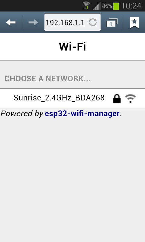
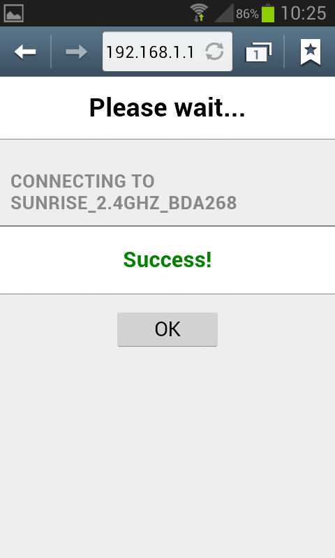
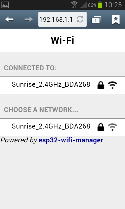
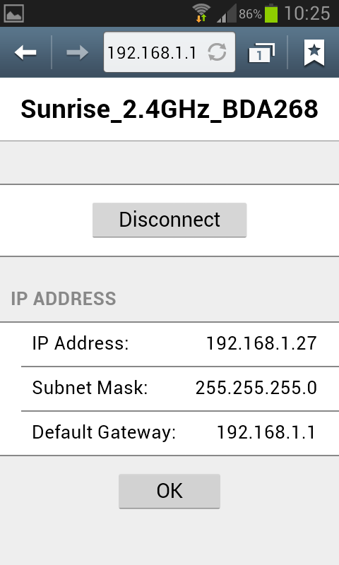
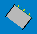
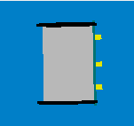
You can use a phone, a tablet or a computer to connect to the robot's WiFi and then you need to open a browser and insert the address 192.168.1.1. The available networks are scanned automatically and listed in the browser page as shown in figure 1. Choose the WiFi signal you want the robot to establish a conection with from the web generated list, and enter the related password; if the password is correct you'll get a message saying that the connection is established as shown in figure 2. After pressing OK you will be redirected to the main page showing the network to which you're connected and the others available nearby as shown in figure 3. If you press on the connected network, then you can see your IP address as shown in figure 4; take note of the address since it will be needed later.
| [1] | [2] | [3] | [4] |
 |
 |
 |
 |
Now the configuration is saved in flash, this means that when the robot is turned on it will read this configuration and try to establish a connection automatically.
Remember that you need to power cycle the robot at least once for the new configuration to be active.
Once the connection is established, the LED2 will be green.
In order to reset the current configuration you need to press the user button for 2 seconds (the LED2 red will turn on), then you need to power cycle the robot to enter access point mode.
Finding the IP address
Often the IP address assigned to the robot will remain the same when connecting to the same network, so if you took note of the IP address in section Network configuration you're ready to go to the next section.
Otherwise you need to connect the robot to the computer with the USB cable, open a terminal and connect to the port labeled Serial Monitor (see chapter Finding the USB serial ports used). Then power cycle the robot and the IP address will be shown in the terminal (together with others informations), as illustrated in the following figure:
Testing the WiFi connection
A dedicated WiFi version of the PC application was developed to communicate with the robot through TCP protocol. You can download the executable from one of the following links:
If you are interested to the source code, you can download it with the command git clone -b wifi --recursive https://github.com/e-puck2/monitor.git
Run the PC application, insert the IP address of the robot in the connection textfield and then click on the Connect button. You should start receiving sensors data and you can send commands to the robot. The LED2 blue will toggle.
Web server
When the robot is in access point mode you can have access to a web page showing the camera image and some buttons that you can use to move the robot; it is a basic example that you can use as a starting point to develop your own web browser interface.
You can use a phone, a tablet or a computer to connect to the robot's WiFi and then you need to open a browser and insert the address 192.168.1.1/monitor.html.
Python examples
Connecting to multiple robots
A simple Python 3 script was developed as a starting point to open a connection with multiple robots and exchange data with them using the WiFi communication protocol. The demo was tested with 10 robots but can be easily extended to connect to more robots.
You can download the script with the command git clone https://github.com/e-puck2/e-puck2_python_wifi_multi.git. The code was tested to work with Python 3.x.
Communication protocol
This section is the hardest part to understand. It outlines all the details about the communication protocols that you'll need to implement in order to communicate with the robot form the computer. So spend a bit of time reading and re-reading this section in order to grasp completely all the details.
Bluetooth and USB
The communication protocol is based on the advanced sercom protocol, used with the e-puck1.x robot. The advanced sercom v2 includes all the commands available in the advanced sercom protocol and add some additional commands to handle the new features of the e-puck2 robot. In particular here are the new commands:
| Command | Description | Return value / set value |
|---|---|---|
-0x08
|
Get all sensors | 
see section Communication protocol: WiFi for the content description |
-0x09
|
Set all actuators | 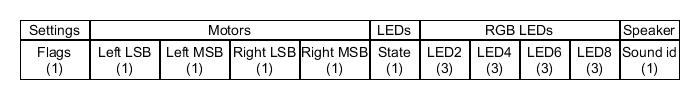
see section Communication protocol: WiFi for the content description |
-0x0A
|
Set RGB LEDs, values from 0 (off) to 100 (completely on) | [LED2_red][LED2_green][LED2_blue][LED4_red][LED4_green][LED4_blue][LED6_red][LED6_green][LED6_blue][LED8_red][LED8_green][LED8_blue]
|
-0x0B
|
Get button state: 0 = not pressed, 1 = pressed | [STATE]
|
-0x0C
|
Get all 4 microphones volumes | [MIC0_LSB][MIC0_MSB][MIC1_LSB][MIC1_MSB][MIC2_LSB][MIC2_MSB][MIC3_LSB][MIC3_MSB]
|
-0x0D
|
Get distance from ToF sensor (millimeters) | [DIST_LSB][DIST_MSB]
|
-0x0E
|
Get SD state: 0 = micro sd not connected, 1 = micro sd connected | [STATE]
|
-0x0F
|
Enable/disable magnetometer: 0 = disable, 1 = enable | [STATE]
|
-0x10
|
Set proximity state: 0 = disable proximity sampling, 1 = enable fast proximity sampling (100 hz), 2 = enable slow proximity sampling (20 hz) | [STATE]
|
-0x0F
|
Enable/disable magnetometer: 0 = disable, 1 = enable | [STATE]
|
WiFi
The communication is based on TCP; the robot create a TCP server and wait for a connection.
Each packet is identified by an ID (1 byte). The following IDs are used to send data from the robot to the computer:
- 0x00 = reserved
- 0x01 = QQVGA color image packet (only the first segment includes this id); packet size (without id) = 38400 bytes; image format = RGB565
- 0x02 = sensors packet; packet size (without id) = 104 bytes; the format of the returned values are based on the advanced sercom protocol and are compatible with e-puck1.x:
- Acc: raw axes values (0=X LSB, 1=X MSB, 2=Y LSB, 3=Y MSB, 4=Z LSB, 5=Z MSB), between -1500 and 1500, resolution is +-2g
- Acceleration expressed in float: acceleration magnitude
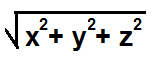 , between 0.0 and about 2600.0 (~3.46 g)
 - Orientation expressed in float: between 0.0 and 360.0 degrees
0.0 deg 90.0 deg 180 deg 270 deg 


- Inclination expressed in float: between 0.0 and 90.0 degrees (when tilted in any direction)
0.0 deg 90.0 deg 
- Gyro: raw axes values (0=X LSB, 1=X MSB, 2=Y LSB, 3=Y MSB, 4=Z LSB, 5=Z MSB), between -32768 and 32767, range is +-250dps
- Magnetometer: raw axes values expressed in float, range is +-4912.0 uT (magnetic flux density expressed in micro Tesla)
- Temp: temperature given in Celsius degrees
- IR proximity (0=IR_0 LSB, 1=IR_0 MSB, ...): between 0 (no objects detected) and 4095 (object near the sensor)
- IR ambient (0=IR_0 LSB, 1=IR_0 MSB, ...): between 0 (strong light) and 4095 (dark)
- ToF distance: distance given in millimeters
- Mic volume (0=MIC_0 LSB, 1=MIC_0 MSB, ...): between 0 and 4095
- Motors steps: 1000 steps per wheel revolution
- Battery:
- uSD state: 1 if the micro sd is present and can be read/write, 0 otherwise
- TV remote data: RC5 protocol
- Selector position: between 0 and 15
- Ground proximity (0=GROUND_0 LSB, 1=GROUND_0 MSB, ...): between 0 (no surface at all or not reflective surface e.g. black) and 1023 (very reflective surface e.g. white)
- Ground ambient (0=GROUND_0 LSB, 1=GROUND_0 MSB, ...): between 0 (strong light) and 1023 (dark)
- Button state: 1 button pressed, 0 button released
- Inclination expressed in float: between 0.0 and 90.0 degrees (when tilted in any direction)
- 0x03 = empty packet (only id is sent); this is used as an acknowledgment for the commands packet when no sensors and no image is requested
The following IDs are used to send data from the computer to the robot:
- 0x80 = commands packet; packet size (without id) = 20 bytes:
- request:
- bit0: 0=stop image stream; 1=start image stream
- bit1: 0=stop sensors stream; 1=start sensors stream
- settings:
- bit0: 1=calibrate IR proximity sensors
- bit1: 0=disable onboard obstacle avoidance; 1=enable onboard obstacle avoidance (not implemented yet)
- bit2: 0=set motors speed; 1=set motors steps (position)
- left and right: when bit2 of
settingsfield is0, then this is the desired motors speed (-1000..1000); when1then this is the value that will be set as motors position (steps) - LEDs: 0=off; 1=on
- bit0: 0=LED1 off; 1=LED1 on
- bit1: 0=LED3 off; 1=LED3 on
- bit2: 0=LED5 off; 1=LED5 on
- bit3: 0=LED7 off; 1=LED7 on
- bit4: 0=body LED off; 1=body LED on
- bit5: 0=front LED off; 1=front LED on
- RGB LEDs: for each LED, it is specified in sequence the value of red, green and blue (0...100)
- sound id: 0x01=MARIO, 0x02=UNDERWOLRD, 0x04=STARWARS, 0x08=4KHz, 0x10=10KHz, 0x20=stop sound
- request:
For example to receive the camera image (stream) the following steps need to be followed:
1) connect to the robot through TCP
2) send the command packet:
0x80 0x01 0x00 0x00 0x00 0x00 0x00 0x00 0x00 0x00 0x00 0x00 0x00 0x00 0x00 0x00 0x00 0x00 0x00 0x00 0x00
3) read the ID (1 byte) and the QQVGA color image pakcet (38400 bytes)
4) go to step 3
Webots
1. Download the last version of Webots for your platform and install it.
2. Program the robot with the WiFi firmware and put the selector in position 15(F). Connect the robot to your WiFi network.
3. Open the example world you can find in the Webots installation directory Webots\projects\robots\gctronic\e-puck\worlds\e-puck2.wbt.
4. Double click the robot, a new small window will appear: insert the IP address of the robot and click connect.
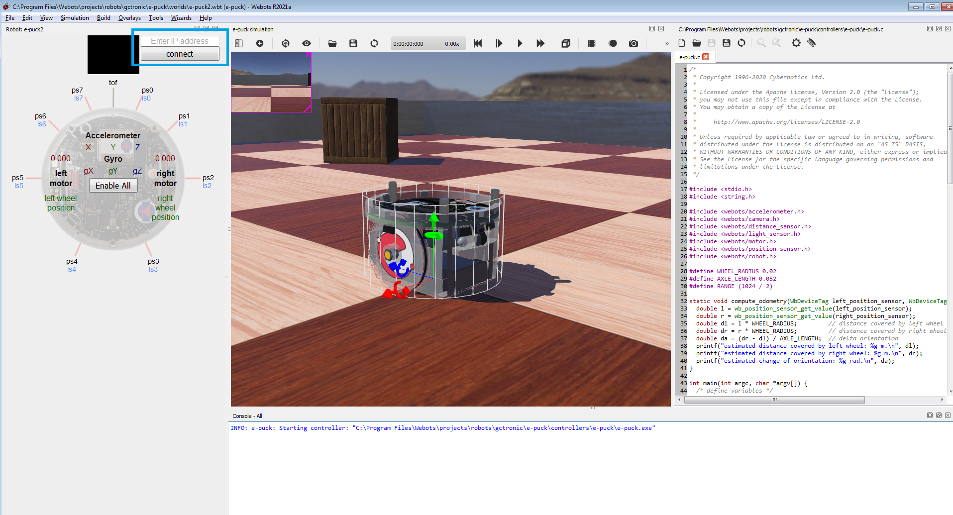
5. Now you can start the demo, the robot will be remote controlled.
For more information have a look at the e-puck Webots guide.
ROS
This chapter explains how to use ROS with the e-puck2 robots by connecting them via Bluetooth or WiFi to the computer that runs the ROS nodes. Basically all the sensors are exposed to ROS and you can also send commands back to the robot through ROS. Both Pyhton and cpp versions are implemented to give the user the possibility to choose its preferred programming language. Here is a general schema:
 Click to enlarge
First of all you need to install and configure ROS, refer to https://wiki.ros.org/Distributions for more informations. This tutorial is based on ROS Kinetic. The same instructions are working with ROS Noetic, beware to use noetic instead of kinetic when installing the packages.
Starting from the work done with the e-puck1 (see E-Puck ROS), we updated the code in order to support the e-puck2 robot.
Initial configuration
The following steps need to be done only once, after installing ROS:
- 1. If not already done, create a catkin workspace, refer to https://wiki.ros.org/catkin/Tutorials/create_a_workspace. Basically you need to issue the following commands:
  mkdir -p ~/catkin_ws/src
  cd ~/catkin_ws/src
  catkin_init_workspace
  cd ~/catkin_ws/
  catkin_make
  source devel/setup.bash
- 2. You will need to add the line
source ~/catkin_ws/devel/setup.bashto your .bashrc in order to automatically have access to the ROS commands when the system is started - 3. Move to
~/catkin_ws/srcand clone the ROS e-puck2 driver repo:- if you are working with Python (only Bluetooth communication supported at the moment):
git clone -b e-puck2 https://github.com/gctronic/epuck_driver - if you are working with cpp:
- Bluetooth communication:
git clone -b e-puck2 https://github.com/gctronic/epuck_driver_cpp - WiFi communication:
git clone -b e-puck2_wifi https://github.com/gctronic/epuck_driver_cpp
- Bluetooth communication:
- if you are working with Python (only Bluetooth communication supported at the moment):
- 4. Install the dependencies:
- ROS:
- gmapping (SLAM) package:
sudo apt-get install ros-kinetic-gmapping - Rviz IMU plugin package:
sudo apt-get install ros-kinetic-rviz-imu-plugin
- gmapping (SLAM) package:
- Python:
- The ROS e-puck2 driver is based on the e-puck2 Python library that requires some dependencies:
- install the Python setup tools:
sudo apt-get install python-setuptools - install the Python image library:
sudo apt-get install python-imaging - install pybluez version 0.22:
sudo pip install pybluez==0.22- install pybluez dependencies:
sudo apt-get install libbluetooth-dev
- install pybluez dependencies:
- install OpenCV:
sudo apt-get install python3-opencv
- install the Python setup tools:
- The ROS e-puck2 driver is based on the e-puck2 Python library that requires some dependencies:
- cpp:
- install the library used to communicate with Bluetooth:
sudo apt-get install libbluetooth-dev - install OpenCV:
sudo apt-get install libopencv-dev- if you are working with OpenCV 4, then you need to change the header include from
#include <opencv/cv.h>to#include <opencv2/opencv.hpp>
- if you are working with OpenCV 4, then you need to change the header include from
- install the library used to communicate with Bluetooth:
- ROS:
- 5. Open a terminal and go to the catkin workspace directory (~/catkin_ws) and issue the command
catkin_make, there shouldn't be errors - 6. Program the e-puck2 robot with the factory firmware and put the selector in position 3 for Bluetooth communication or in position 15(F) for WiFi Communication
- 7. Program the radio module with the correct firmware:
- Bluetooth communication: use the factory firmware
- WiFi communication: use the WiFi firmware
Running the Python ROS node
First of all get the last version of the ROS e-puck2 driver from github. Move to ~/catkin_ws/src and issue: git clone -b e-puck2 https://github.com/gctronic/epuck_driver.
Then build the driver by opening a terminal and issueing the command catkin_make from within the catkin workspace directory (e.g. ~/catkin_ws).
Moreover make sure the node is marked as executable by opening a terminal and issueing the following command from within the catkin workspace directory (e.g. ~/catkin_ws): chmod +x ./src/epuck_driver/scripts/epuck2_driver.py.
Before actually starting the e-puck2 node you need to configure the e-puck2 robot as Bluetooth device in the system, refer to section Connecting to the Bluetooth.
Once the robot is paired with the computer, you need to take note of its MAC address (this will be needed when launching the ROS node). To know the MAC address of a paired robot, go to System Settings, Bluetooth and select the robot; once selected you'll see in the right side the related MAC address.
First thing to do before launching the script file is running the roscore, open another terminal tab and issue the command roscore.
Now you can finally start the e-puck2 ROS node, for this purposes there is a launch script (based on roslaunch).
Open a terminal and issue the following command: roslaunch epuck_driver epuck2_controller.launch epuck2_address:='B4:E6:2D:EB:9C:4F'.
B4:E6:2D:EB:9C:4F is the e-puck2 Bluetooth MAC address that need to be changed accordingly to your robot.
If all is going well you'll see the robot make a blink meaning it is connected and ready to exchange data and rviz will be opened showing the informations gathered from the topics published by the e-puck2 driver node.
The launch script is configured also to run the gmapping (SLAM) node that let the robot construct a map of the environment; the map is visualized in real-time directly in the rviz window. The gmapping package provides laser-based SLAM (Simultaneous Localization and Mapping) and since the e-puck2 has no laser sensor, the information from the 6 proximity sensors on the front side of the robot are interpolated to get 19 laser scan points.
The following figures show all the topics published by the e-puck2 driver node (left) and the rviz interface (right):
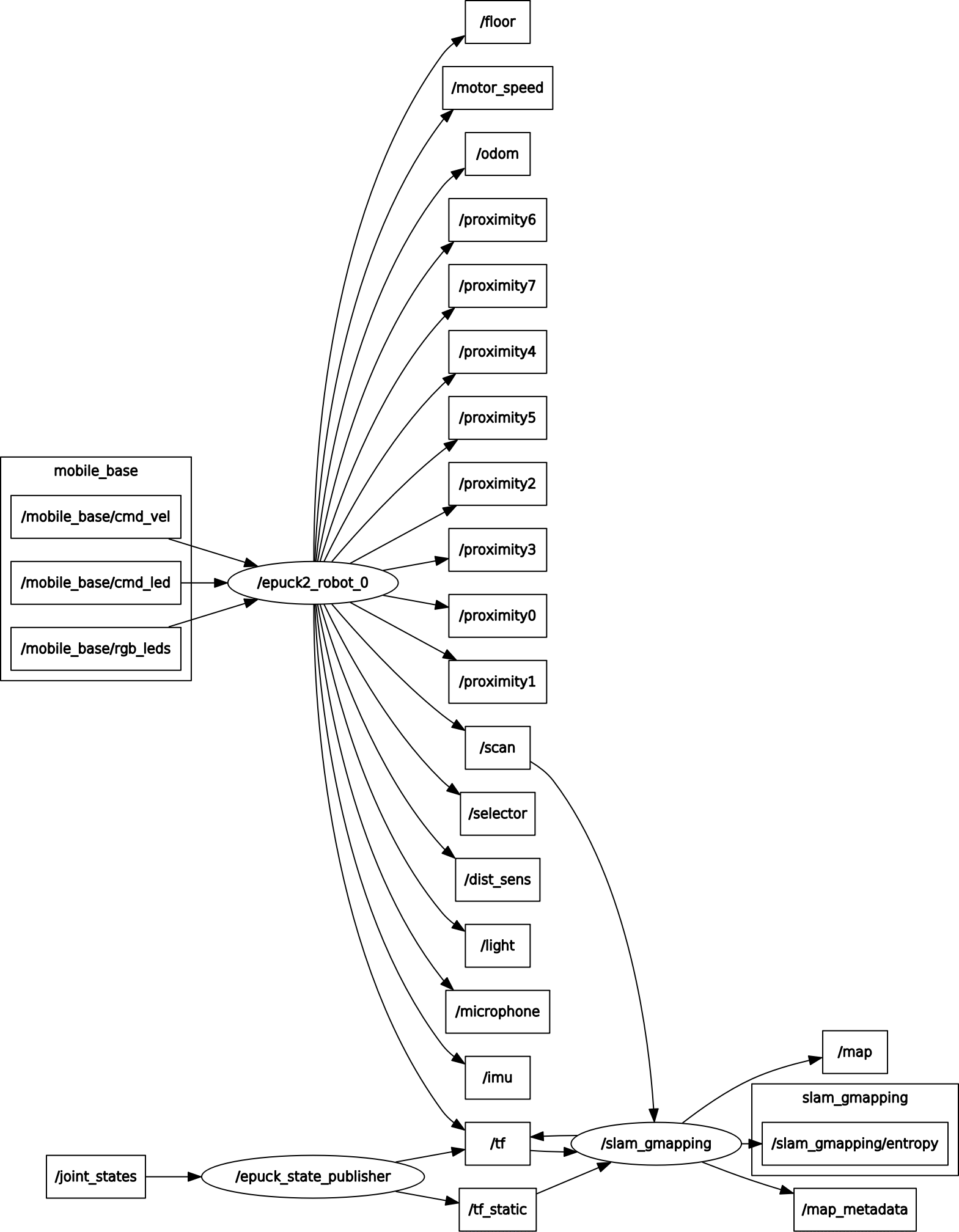 Click to enlarge
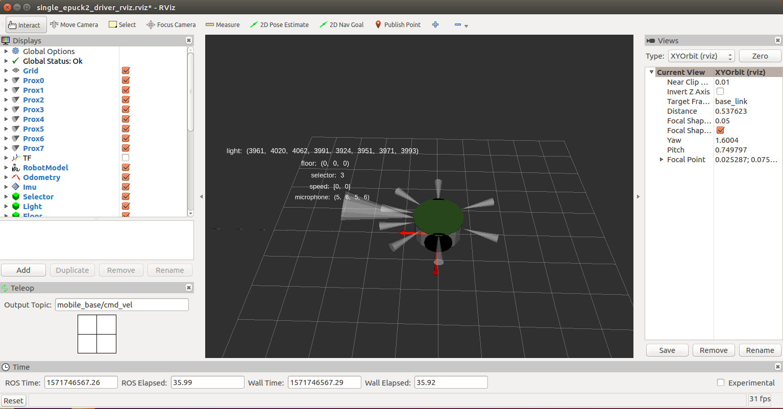 Click to enlarge
Running the cpp ROS node
There is a small difference at the moment between the Bluetooth and WiFi versions of the ROS node: the WiFi ROS node supports also the publication of the magnetometer data.
Bluetooth
First of all get the last version of the ROS e-puck2 driver from github. Move to ~/catkin_ws/src and issue: git clone -b e-puck2 https://github.com/gctronic/epuck_driver_cpp.
Then build the driver by opening a terminal and issueing the command catkin_make from within the catkin workspace directory (e.g. ~/catkin_ws).
Before actually starting the e-puck2 node you need to configure the e-puck2 robot as Bluetooth device in the system, refer to section Connecting to the Bluetooth.
Once the robot is paired with the computer, you need to take note of its MAC address (this will be needed when launching the ROS node). To know the MAC address of a paired robot, go to System Settings, Bluetooth and select the robot; once selected you'll see in the right side the related MAC address.
First thing to do before launching the script file is running the roscore, open another terminal tab and issue the command roscore.
Now you can finally start the e-puck2 ROS node, for this purposes there is a launch script (based on roslaunch).
Open a terminal and issue the following command: roslaunch epuck_driver_cpp epuck2_controller.launch epuck2_address:='B4:E6:2D:EB:9C:4F'.
B4:E6:2D:EB:9C:4F is the e-puck2 Bluetooth MAC address that need to be changed accordingly to your robot.
If all is going well the robot will be ready to exchange data and rviz will be opened showing the informations gathered from the topics published by the e-puck2 driver node.
The launch script is configured also to run the gmapping (SLAM) node that let the robot construct a map of the environment; the map is visualized in real-time directly in the rviz window. The gmapping package provides laser-based SLAM (Simultaneous Localization and Mapping) and since the e-puck2 has no laser sensor, the information from the 6 proximity sensors on the front side of the robot are interpolated to get 19 laser scan points.
WiFi
First of all get the last version of the ROS e-puck2 driver from github. Move to ~/catkin_ws/src and issue: git clone -b e-puck2_wifi https://github.com/gctronic/epuck_driver_cpp.
Then build the driver by opening a terminal and issueing the command catkin_make from within the catkin workspace directory (e.g. ~/catkin_ws).
Before actually starting the e-puck2 node you need to connect the e-puck2 robot to your WiFi network, refer to section Connecting to the WiFi.
First thing to do before launching the script file is running the roscore, open another terminal tab and issue the command roscore.
Now you can finally start the e-puck2 ROS node, for this purposes there is a launch script (based on roslaunch).
Open a terminal and issue the following command: roslaunch epuck_driver_cpp epuck2_controller.launch epuck2_address:='192.168.1.20'.
192.168.1.20 is the e-puck2 IP address that need to be changed accordingly to your robot.
If all is going well the robot will be ready to exchange data and rviz will be opened showing the informations gathered from the topics published by the e-puck2 driver node.
The launch script is configured also to run the gmapping (SLAM) node that let the robot construct a map of the environment; the map is visualized in real-time directly in the rviz window. The gmapping package provides laser-based SLAM (Simultaneous Localization and Mapping) and since the e-puck2 has no laser sensor, the information from the 6 proximity sensors on the front side of the robot are interpolated to get 19 laser scan points.
The refresh rate of the topics is about 11 Hz when the camera image is enabled (see e-puck2_topics_wifi_refresh_camon.pdf) and about 50 Hz when the camera image is disabled (see e-puck2_topics_wifi_refresh_camoff.pdf). The same graphs can be created using the command rosrun tf view_frames.
The following figure shows all the topics published by the e-puck2 WiFi ROS node. The same graph can be created using the command rqt_graph.
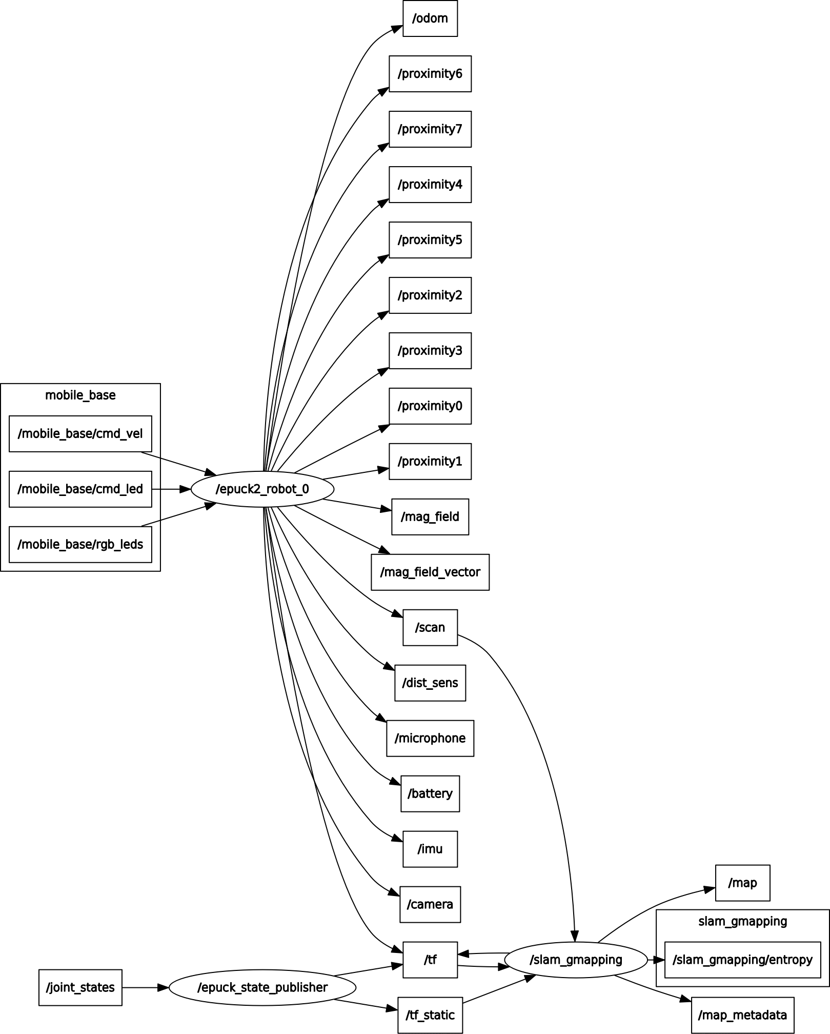 Click to enlarge
Move the robot
You have some options to move the robot.
The first one is to use the rviz interface: in the bottom left side of the interface there is a Teleop panel containing an interactive square meant to be used with differential drive robots. By clicking in this square you'll move the robot, for instance by clicking on the top-right section, then the robot will move forward-right.
The second method to move the robot is using the ros-kinetic-turtlebot-teleop ROS package. If not already done, you can install this package by issueing sudo apt-get install ros-kinetic-turtlebot-teleop.
There is a lunch file in the e-puck2 ROS driver that configures this package in order to be used with the e-puck2 robot. To start the launch file, issue the following command roslaunch epuck_driver epuck2_teleop.launch, then follow the instructions printed on the terminal to move the robot.
The third method is by directly publishing on the /mobile_base/cmd_vel topic, for instance by issueing the following command rostopic pub -1 /mobile_base/cmd_vel geometry_msgs/Twist -- '[0.0, 0.0, 0.0]' '[0.0, 0.0, 1.0]' the robot will rotate on the spot, instead by issueing the following command rostopic pub -1 /mobile_base/cmd_vel geometry_msgs/Twist -- '[4.0, 0.0, 0.0]' '[0.0, 0.0, 0.0]' the robot will move straight forward.
Beware that there shouldn't be any other node publishing on the /mobile_base/cmd_vel topic, otherwise your commands will be overwritten.
Control the RGB LEDs
The general command to change the RGB LEDs colors is the following:
rostopic pub -1 /mobile_base/rgb_leds std_msgs/UInt8MultiArray "{data: [LED2 red, LED2 green, LED2 blue, LED4 red, LED4 green, LED4 blue, LED6 red, LED6 green, LED6 blue, LED8 red, LED8 green, LED8 blue]}"
The values range is from 0 (off) to 100 (completely on). Have a look at the e-puck2 overview to know the position of the RGB LEDs.
For instance to set all the RGB LEDs to red, issue the following command:
rostopic pub -1 /mobile_base/rgb_leds std_msgs/UInt8MultiArray "{data: [100,0,0, 100,0,0, 100,0,0, 100,0,0]}"
To turn off all the RGB LEDs issue the following command:
rostopic pub -1 /mobile_base/rgb_leds std_msgs/UInt8MultiArray "{data: [0,0,0, 0,0,0, 0,0,0, 0,0,0]}"
Control the LEDs
The general command to change the LEDs state is the following:
rostopic pub -1 /mobile_base/cmd_led std_msgs/UInt8MultiArray "{data: [LED1, LED3, LED5, LED7, body LED, front LED]}"
The values are: 0 (off), 1 (on) and 2 (toggle). Have a look at the e-puck2 overview to know the position of the LEDs.
For instance to turn on LED1, LED5, body LED and front LED, issue the following command:
rostopic pub -1 /mobile_base/cmd_led std_msgs/UInt8MultiArray "{data: [1,0,1,0,1,1]}"
To toggle the state of all the LEDs issue the following command:
rostopic pub -1 /mobile_base/cmd_led std_msgs/UInt8MultiArray "{data: [2,2,2,2,2,2]}"
Visualize the camera image
By default the camera is disabled to avoid communication delays. In order to enable it and visualize the image through ROS you need to pass an additional parameter cam_en to the launch script as follows:
- Python:
roslaunch epuck_driver epuck2_controller.launch epuck2_address:='B4:E6:2D:EB:9C:4F' cam_en:='true' - cpp:
- Bluetooth:
roslaunch epuck_driver_cpp epuck2_controller.launch epuck2_address:='B4:E6:2D:EB:9C:4F' cam_en:='true' - WiFi:
roslaunch epuck_driver_cpp epuck2_controller.launch epuck2_address:='192.168.1.20' cam_en:='true'
- Bluetooth:
Then with the Python ROS node you need to open another terminal and issue the command rosrun image_view image_view image:=/camera that will open a window with the e-puck2 camera image.
With the cpp ROS node the image is visualized directly in the Rviz window (on the right).
When using the Bluetooth ROS node, by default the image is greyscale and its size is 160x2, but you can change the image parameters in the launch script.
Instead when using the WiFi node, the image is RGB565 and its size is fixed to 160x120 (you can't change it).
Multiple robots
There is a lunch script file designed to run up to 4 robots simultaneously, you can find it in ~/catkin_ws/src/epuck_driver_cpp/launch/multi_epuck2.launch. Here is an example to run 2 robots:
roslaunch epuck_driver_cpp multi_epuck2.launch robot_addr0:='192.168.1.21' robot_addr1:='192.168.1.23'
After issueing the command, rviz will be opened showing the values of all the 4 robots; it is assumed that the robots are placed in a square (each robot in each corner) of 20 cm.
Beware that this launch script is available only in the WiFi branch, but it can be used as a starting point also for the Bluetooth communication.
Troubleshooting
Robot state publisher
If you get an error similar to the following when you start a node with roslaunch:
ERROR: cannot launch node of type [robot_state_publisher/state_publisher]: Cannot locate node of type [state_publisher] in package [robot_state_publisher]. Make sure file exists in package path and permission is set to executable (chmod +x)
Then you need to change the launch file from:
<node name="robot_state_publisher" pkg="robot_state_publisher" type="state_publisher" />
To:
<node name="robot_state_publisher" pkg="robot_state_publisher" type="robot_state_publisher" />
This is due to the fact that state_publisher was a deprecated alias for the node named robot_state_publisher (see https://github.com/ros/robot_state_publisher/pull/87).
Tracking
Some experiments are done with the SwisTrack software in order to be able to track the e-puck2 robots through a color marker placed on top of the robots.
The requirements are the following:
- e-puck robots equipped with a color marker attached on top of the robot; beware that there should be a white border of about 1 cm to avoid wrong detection (marker merging). The colors marker were printed with a laser printer.
- USB webcam with a resolution of at least 640x480. In our tests we used the
Trust SpotLight Pro. - Windows OS: the SwisTrack pre-compiled package was built to run in Windows. Moreover the controller example depends on Windows libraries.
Anyway it's important to notice that SwisTrack is multiplatform and that the controller code can be ported to Linux. - An arena with uniform light conditions to make the detection more robust.
Controller example
In this example we exploit the SwisTrack blobs detection feature in order to detect the color markers on top of the robots and then track these blob with a Nearest Neighbour tracking algorithm.
The SwisTrack application get an image from the USB camera, then applies some conversions and thresholding before applying the blobs detection and finally tracks these blobs. All the data, like the blob's positions, are published to the network (TCP).
The controller is a separate application that receives the data from SwisTrack through the network and opens a Bluetooth connection with each robot in order to remote control them. In the example, the informations received are printed in the terminal while moving the robots around (obstacles avoidance).
The following schema shows the connections schema:
![]()
Follow these steps to run the example:
- program all the e-puck2 robots with the last factory firmware (see section Firmware update) and put the selector in position 3
- pair the robots with the computer, refer to section Connecting to the Bluetooth
- the controller example is based on the C++ remote library, so download it
- download the controller example by issueing the following command:
git clone https://github.com/e-puck2/e-puck2_tracking_example.
When building the example, make sure that both the library and the example are in the same directory - download the pre-compiled SwisTrack software and extract it. The SwisTrack executable can be found in
SwisTrackEnvironment/SwisTrack - Release.exe - prepare the arena: place the USB camera on the roof pointing towards the robots. Download the markers and attach one of them on top of each robot.
- download the configuration files package for SwisTrack and extract it. Run the SwisTrack executable and open the configuration file called
epuck2.swistrack. All the components to accomplish the tracking of 2 robots should be loaded automatically.
If needed you can tune the various components to improve the blobs detection in your environment or for tracking more robots. - Run the controller example: at the beginning you must enter the Bluetooth UART port numbers for the 2 robots. Then the robots will be moved slightly in order to identify which robot belong to which blob. Then the controller loop is started sending motion commands to the robots for doing obstacles avoidance and printing the data received from SwisTrack in the terminal.
The following image shows the example running:
![]()
Matlab
A Matlab interface is available in the following repository https://github.com/gctronic/e-puck-library/tree/master/tool/ePic. This interface was developed for the e-puck version 1 robot but it is compatible also with e-puck version 2 robot since it is based on the advanced sercom protocol.