Elisa and Omnivision Module V2: Difference between pages
No edit summary |
No edit summary |
||
| Line 1: | Line 1: | ||
=Overview= | |||
<span class="plainlinks">[https://www.gctronic.com/doc/images/omnivision-v2-epuck-3.jpg <img width=200 src="https://www.gctronic.com/doc/images/omnivision-v2-epuck-3-small.jpg">]</span> | |||
< | <span class="plainlinks">[https://www.gctronic.com/doc/images/omnivision-v2-epuck-2.jpg <img width=200 src="https://www.gctronic.com/doc/images/omnivision-v2-epuck-2-small.jpg">]</span> | ||
<span class="plainlinks">[https://www.gctronic.com/doc/images/omnivision-v2-epuck-4.jpg <img width=200 src="https://www.gctronic.com/doc/images/omnivision-v2-epuck-4-small.jpg">]</span> <br/> | |||
The omnivision module is upgraded with a microcontroller directly mounted on the extension that is responsible of handling the 3 RGB leds; the power of the leds can be set through I2C.<br/> | |||
The camera mounted on the extension is an USB 2.0 camera with a maximum resolution of 1280x1024 and a potential framerate of 30 fps. Omnivision module may contain different image sensors depending on shipment date, in particular: | |||
* the Targus Micro Webcam | |||
* the Trust SpotLight Pro | |||
The robot frontal camera below can still be used independently since this camera is connected either to the USB OTG or to the USB HOST of the e-puck gumstix extension. | |||
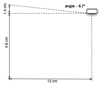
The field of view is up to about 7 degrees over the horizon for the Trust SpotLight Pro, as shown in the following figure:<br/> | |||
<span class="plainlinks">[https://www.gctronic.com/doc/images/omnivision-trust-fieldview.jpg <img width=400 src="https://www.gctronic.com/doc/images/omnivision-trust-fieldview.jpg">]</span><br/> | |||
The same apply for the Targus camera as shown in the following figure:<br/> | |||
<span class="plainlinks">[https://www.gctronic.com/doc/images/omnivision-targus-fieldview.jpg <img width=400 src="https://www.gctronic.com/doc/images/omnivision-targus-fieldview.jpg">]</span> | |||
==Camera specification== | |||
{| cellspacing="0" border="1" | |||
|Name | |||
|<b>Targus Micro Webcam AVC05EU</b> | |||
|<b>Trust SpotLight Pro</b> | |||
|- | |||
|Supported resolutions | |||
|1280x1024, 640x480, 352x288, 176x144, 160x120 | |||
|1280x1024, 640x480, 352x288, 176x144, 160x120 | |||
<!-- |- | |||
|Viewing angle, horizontal | |||
|66.5 ° | |||
| - | |||
--> | |||
|- | |||
|Maximum frame rate | |||
|30 fps | |||
|30 fps | |||
|- | |||
<!-- | |||
|Sensor type | |||
|CMOS | |||
| | |||
--> | |||
<!-- | |||
|- | |||
|Camera focusing range | |||
|0.3 m - infinite | |||
| - | |||
--> | |||
<!-- | |||
|- | |||
|Consumption | |||
| about 150 mA (active) | |||
| | |||
--> | |||
<!-- | |||
|Chipset | |||
| | |||
| Microdia | |||
--> | |||
|} | |||
= | =Getting started= | ||
==1. Software== | |||
As with the gumstix extension, a specific firmware must be charged on the e-puck when working with this extension, it can be downloaded from section [https://www.gctronic.com/doc/index.php/E-Puck#Standard_firmware E-Puck#Standard_firmware]. Remember to put the selector in position 10.<br/> | |||
The system on the micro sd is the same used for the gumstix extension alone, refer to section [https://www.gctronic.com/doc/index.php/Overo_Extension#File_system_image https://www.gctronic.com/doc/index.php/Overo_Extension#File_system_image] for more informations. | |||
The | ==2. Terminal configuration== | ||
Execute a terminal program (e.g. minicom) and configure the connection with 115200-8N1. The serial device path should be typically something like "/dev/ttyUSB0". Make sure that the flow control parameter of minicom called "Hardware" is set to "No". | |||
Once the boot is terminated login with user=root and password=root. | |||
= | ==3. WiFi== | ||
The nano WiFi dongle shipped with the extension board is an Edimax EW-7811Un, based on a Realtek chipset (RTL8192cu). | |||
The | The device isn't recognized automatically at boot, so you need to follow these steps in order to enable and use it: | ||
# turn on the robot and login with user=root, password=root | |||
# if the WiFi dongle is connected to the USB OTG you need to activate typing ''./scripts/gumstix-common/usbenable otg'' | |||
# type ''insmod 8192cu.ko'' (the kernel module is located in /home/root); the wifi dongle should be recognized and a wlanX device created | |||
# type ''ifconfig wlanX up'' (where X is a number) to turn on the device; now the wifi can be configured and used normally | |||
= | =RGB leds= | ||
The | The RGB leds can be controlled from the ''gumstix-side'' through the I2C (400 KHz). The I2C address is 0x61 and to change the leds state all the values for each led need to be sent as follow: R1, G1, B1, R2, G2, B2, R3, G3, B3. <br/> | ||
Once logged in it's possible to execute a demo to pilote all the 3 RGB leds through I2C: | |||
* type ''./demos/omnivision-v2/omnivision-i2c R1 G1 B1 R2 G2 B2 R3 G3 B3'' where the Rx,Gx,Bx are the values you would like to set (ranging from 0 to 255) | |||
You can download the source code from the following link [https://projects.gctronic.com/omnicam/omnivision-i2c-clean.c omnivision-i2c-clean.c].<br/> | |||
It was noticed that when the leds are turned on they can somehow create some reflex in the resulting image; in order to avoid this effect a simple solution would be to put a small piece of black tape on top of them. | |||
Refer to the section [https://www.gctronic.com/doc/index.php/Overo_Extension#3.3V_and_5V_source https://www.gctronic.com/doc/index.php/Overo_Extension#3.3V_and_5V_source] for more information about the RGB usage. | |||
= | =Camera= | ||
If the camera is connected to the USB OTG port you need to issue the following command to enable it (from ''/home/root/scripts/gumstix-common/'' directory): | |||
<pre> | |||
./usbenable otg | |||
</pre> | |||
After this command a new device (''/dev/video1'') should be created automatically. <br/> | |||
If the camera is connected to the USB HOST port then the camera is recognized automatically and the device ''/dev/video1'' should be already available.<br/> | |||
== | ==Image streaming== | ||
You can test and see the camera image using mjpeg-streamer; this tool is already configured with a web server in the system image so you can follow these steps: | |||
# configure the network in order to be able to communicate between the gumstix and the computer | |||
# issue the following commands: | |||
<pre> | |||
export LD_LIBRARY_PATH=/usr/local/mjpg-streamer/:$LD_LIBRARY_PATH | |||
/usr/local/mjpg-streamer/mjpg_streamer -i "input_uvc.so -y -d /dev/video1" -o "output_http.so -p 8090 -w /usr/local/mjpg-streamer/www" | |||
</pre> | |||
# open a browser in the computer and insert the address ''https://gumstix-ip:8090'' where ''gumstix-ip'' is the network address assigned to the gumstix | |||
You can use also your phone to access the webserver. | |||
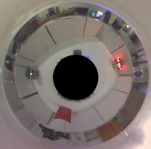
The following figure shows an example of a 640x480 image received through the broswer: <br/> | |||
<span class="plainlinks">[https://www.gctronic.com/img2/omnivision-v2-image640x480.jpg <img width=200 src="https://www.gctronic.com/img2/omnivision-v2-image640x480-small.jpg">]</span> <br/> | |||
For the post-processing of the image refers to the section [https://www.gctronic.com/doc/index.php/Omnivision_Module#Image_unwrapping https://www.gctronic.com/doc/index.php/Omnivision_Module#Image_unwrapping].<br/> | |||
==Image grabbing== | |||
===Video 4 linux=== | |||
The [https://www.gctronic.com/doc/index.php/Overo_Extension#Images_grabbing_.28camera_driver.29 ''v4l2grab'' application] can be used to grab an image from the camera with the following command: | |||
<pre> | |||
./v4l2grab -d /dev/video1 -o image.jpg -f 1 -W 352 -H 288 | |||
</pre> | |||
< | |||
- | |||
- | |||
- | |||
- | |||
= | <!--<font style="color:red"> The current driver (UVC) of the system image supports only resolution up to 640x480.</font>--> | ||
<font style="color:red"> Currently the maximum resolution is 352x288 from the OTG port, we're working to solve this limitation. From the USB HOST there is no known limitation.</font> | |||
== | ===OpenCV=== | ||
An example demo was implemented to show how to interact with OpenCV and the Omnvision extension. In this demo a color blob is tracked; the target color range need to be passed as argument (HSV color space), the parameters in sequence are: <code>Hmin Hmax Smin Smax Vmin Vmax debugFlag</code> (values between 0 and 255, debugFlag = 0 or 1). The robot is rotated in place to track the detected blob. | |||
You can download the source code from the following link [https://projects.gctronic.com/omnicam/blob-tracking-opencv-rev10.zip blob-tracking-opencv.zip].<br/> | |||
In order to build the code follow these steps: | |||
# install the toolchain: <code>sudo apt-get install gcc-arm-linux-gnueabi g++-arm-linux-gnueabi</code> | |||
# build using the makefile included in the zip file: <code>make</code> | |||
Before running the application you need to update some libraries on the gumstix system following these steps (this need to be done only once): | |||
# configure the network in order to have internet access | |||
# update the package manager repo: <code>echo 'src/gz base https://feeds.angstrom-distribution.org/feeds/v2012.12/ipk/eglibc/armv7a-vfp-neon/base/' > /etc/opkg/base-feed.conf</code> | |||
# add <code>arch armv7a-vfp-neon 45</code> to the file <code>/etc/opkg/arch.conf</code> | |||
# <code>opkg update</code> | |||
# <code>opkg install libc6</code> | |||
# <code>opkg install libstdc++6</code> | |||
# optionally you can also remove some warnings related to the update by running the following script [https://projects.gctronic.com/omnicam/remove-warnings.sh remove-warnings.sh] | |||
Once the system is updated, you can copy the executable <code>omniOpenCVblobDetection</code> on the gumstix system and run it. Basically with the HSV range you define a target color, then once the application is started you can move the target around the robot and the robot should try to orient towards it. | |||
== | ==Settings== | ||
You can modify the camera parameters to better suit your needs, here are the steps to install the <code>v4l2-ctl</code> utility for doing that: | |||
# configure internet access | |||
# make a copy of the current repo for the package source: <code>mv /etc/opkg/base-feed.conf /dest-dir</code> | |||
# add the new repo: <code>echo 'src/gz base https://feeds.angstrom-distribution.org/feeds/unstable/ipk/glibc/armv7a/base' > /etc/opkg/base-feed.conf</code> | |||
# issue the command <code>opkg update</code> | |||
# place the file [https://projects.gctronic.com/omnicam/v4l-utils_0.8.1-r0.6_armv7a.ipk v4l-utils_0.8.1-r0.6_armv7a.ipk] in the home directory and then issue: <code>opkg install v4l-utils_0.8.1-r0.6_armv7a.ipk</code> | |||
Once you install the utility, you can have a list of all available camera parameters by issueing the command <code>v4l2-ctl -L</code>.<br/> | |||
For example to change the saturation you issue the command: <code>v4l2-ctl --device=1 -c saturation=128</code> | |||
< | |||
= | =Charging= | ||
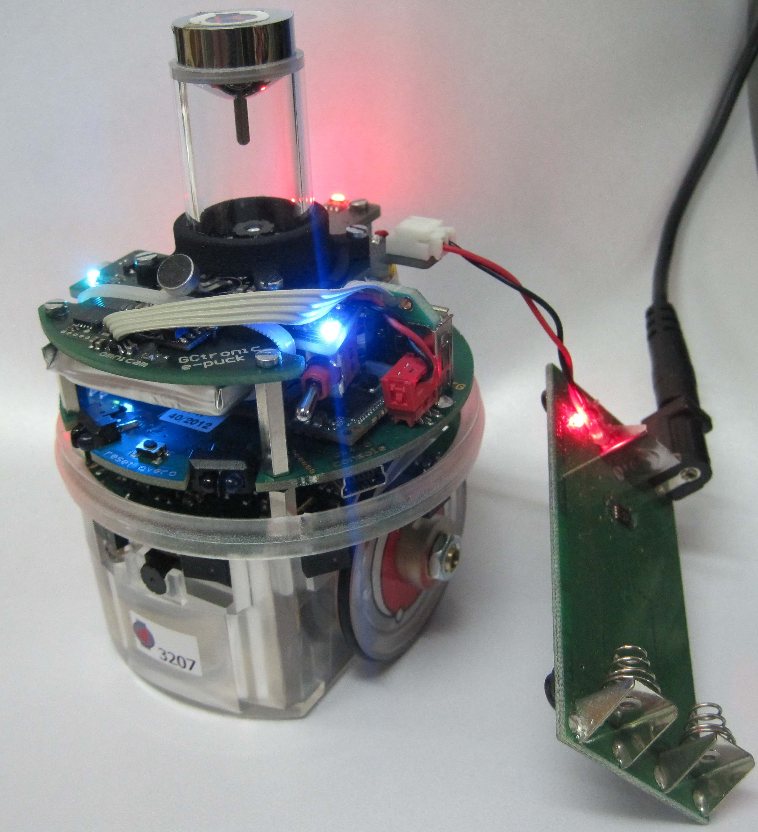
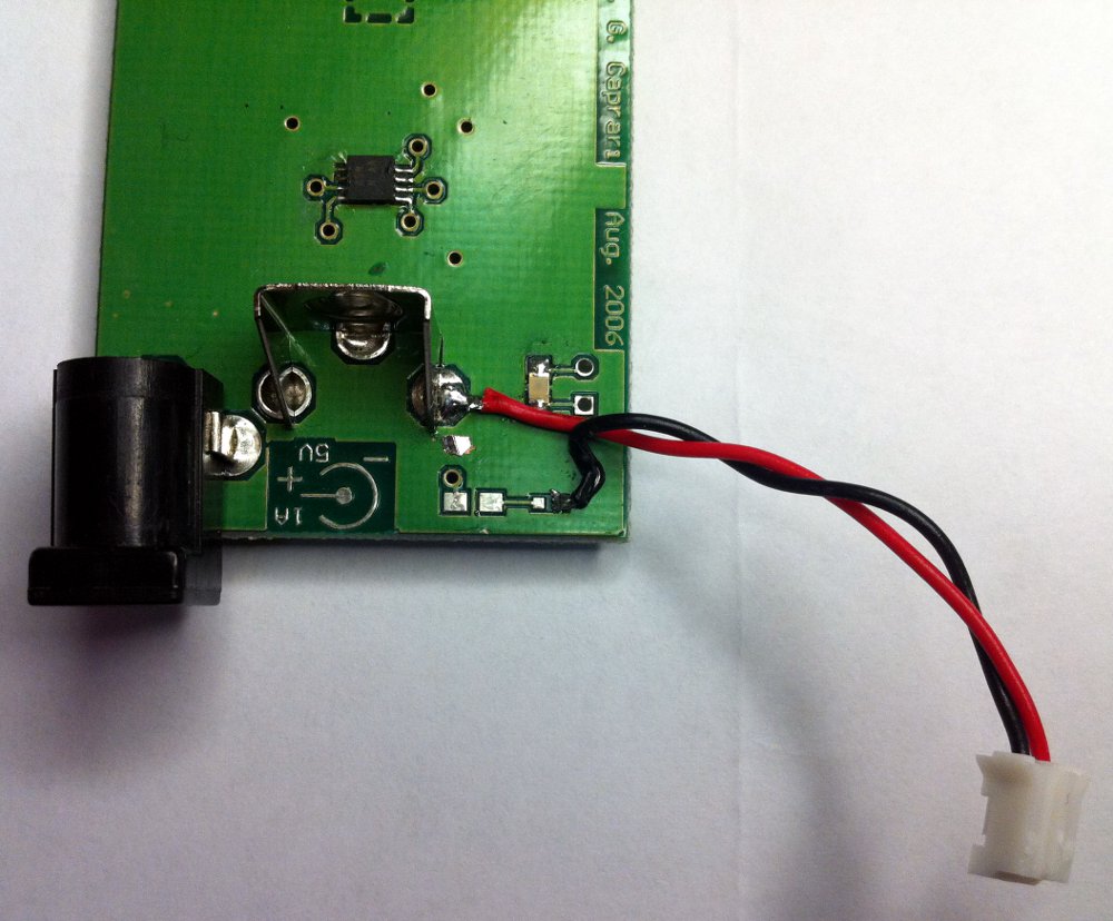
The omnivsion module incorporates an additional battery that can be charged with the e-puck battery charger, but it needs cabling (provided together with the extension) as illustrated in the following figures: <br/> | |||
The | <span class="plainlinks">[https://www.gctronic.com/doc/images/omnivision-v2-epuck-charger.jpg <img width=200 src="https://www.gctronic.com/doc/images/omnivision-v2-epuck-charger-small.jpg">]</span> | ||
<span class="plainlinks">[https://www.gctronic.com/doc/images/omnivision-charger-soldering.jpg <img width=200 src="https://www.gctronic.com/doc/images/omnivision-charger-soldering-small.jpg">]</span> | |||
= | =Extension firmware= | ||
The | The firmware programmed in the microcontroller mounted on the extension is freely available from the following link [https://projects.gctronic.com/omnicam/omnivision-uc-firmware.zip omnivision-uc-firmware.zip]. The project is created with MPLAB IDE from Microchip. | ||
Latest revision as of 11:49, 27 January 2023
1 Overview
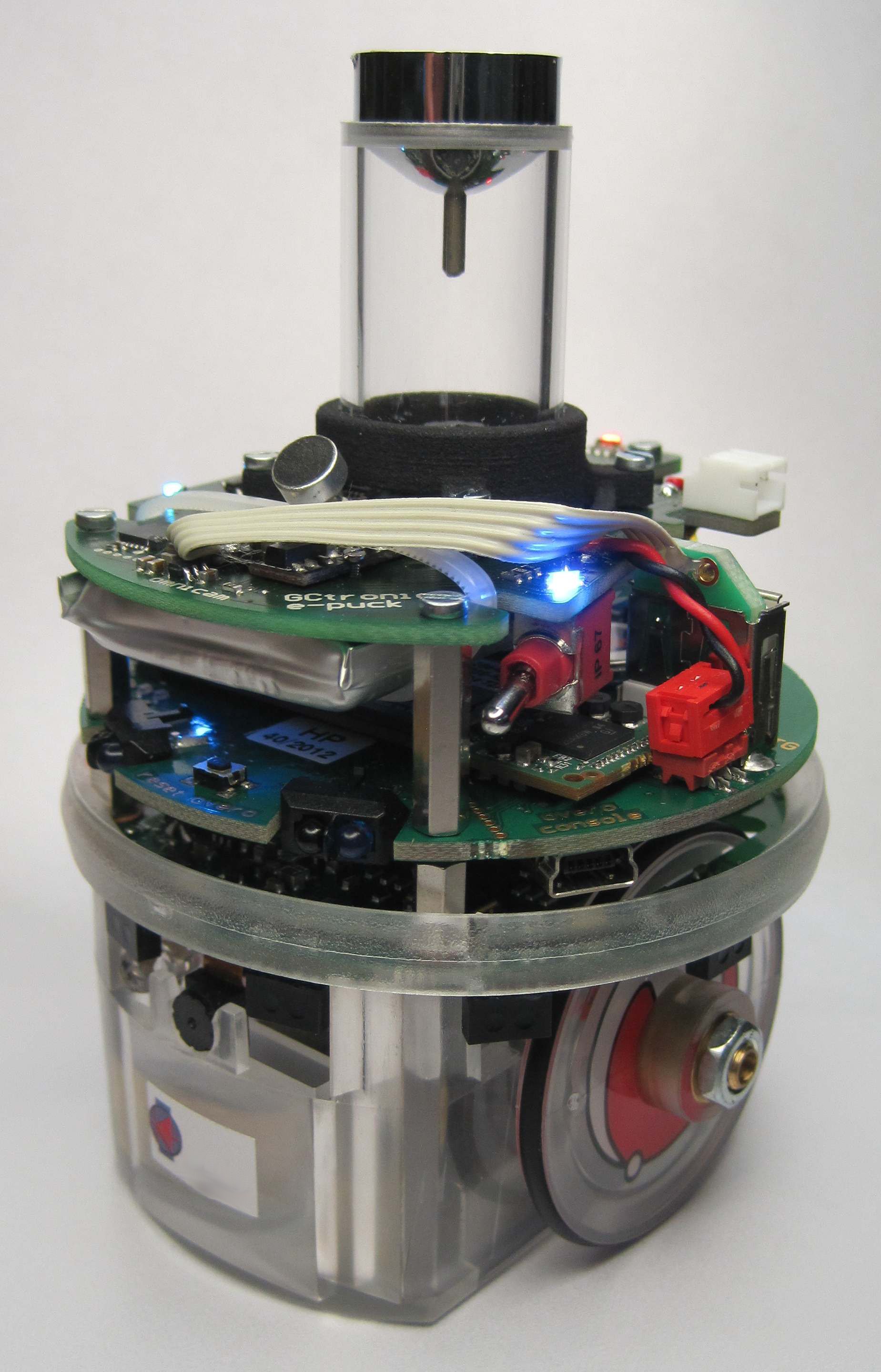
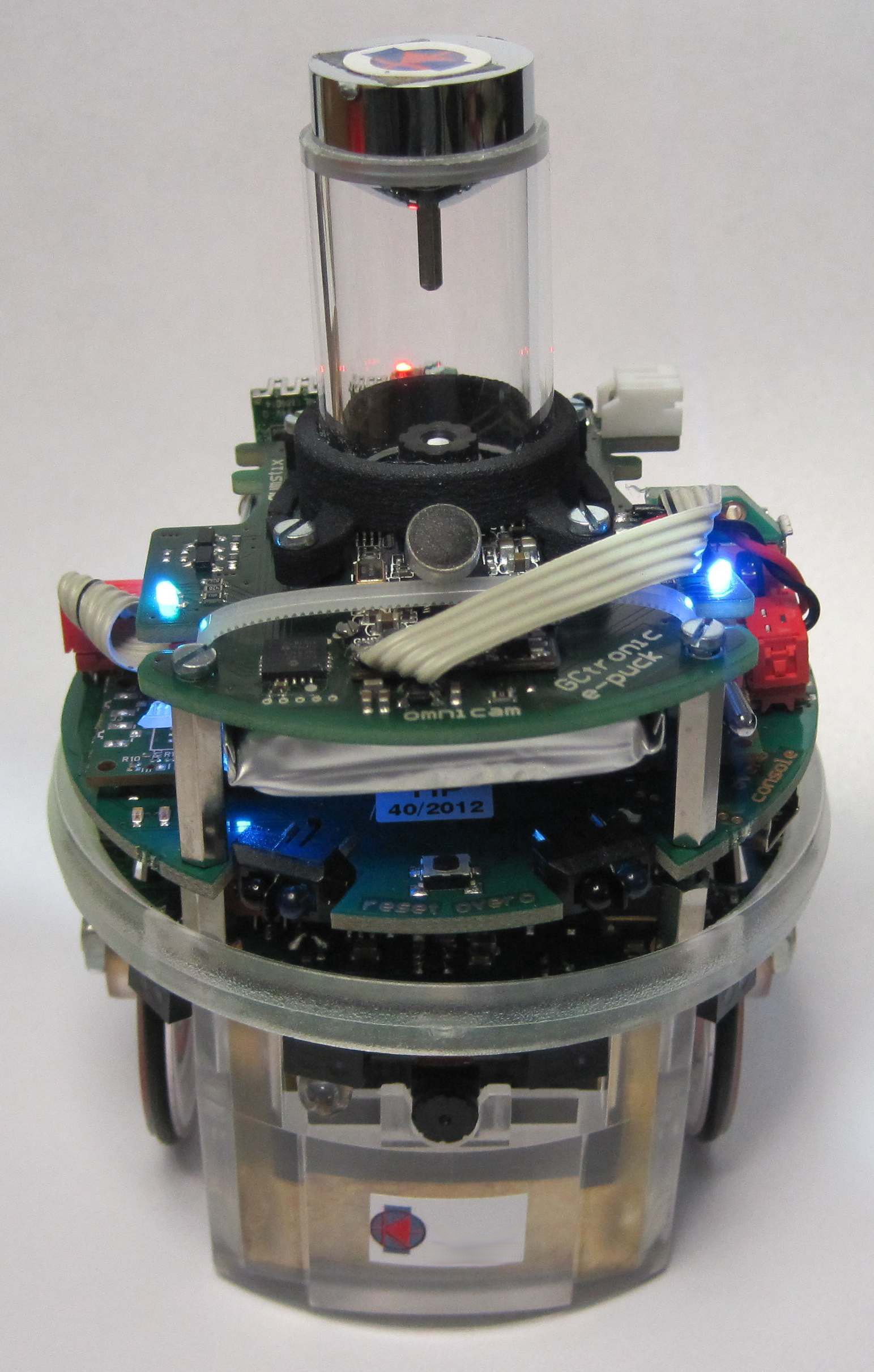
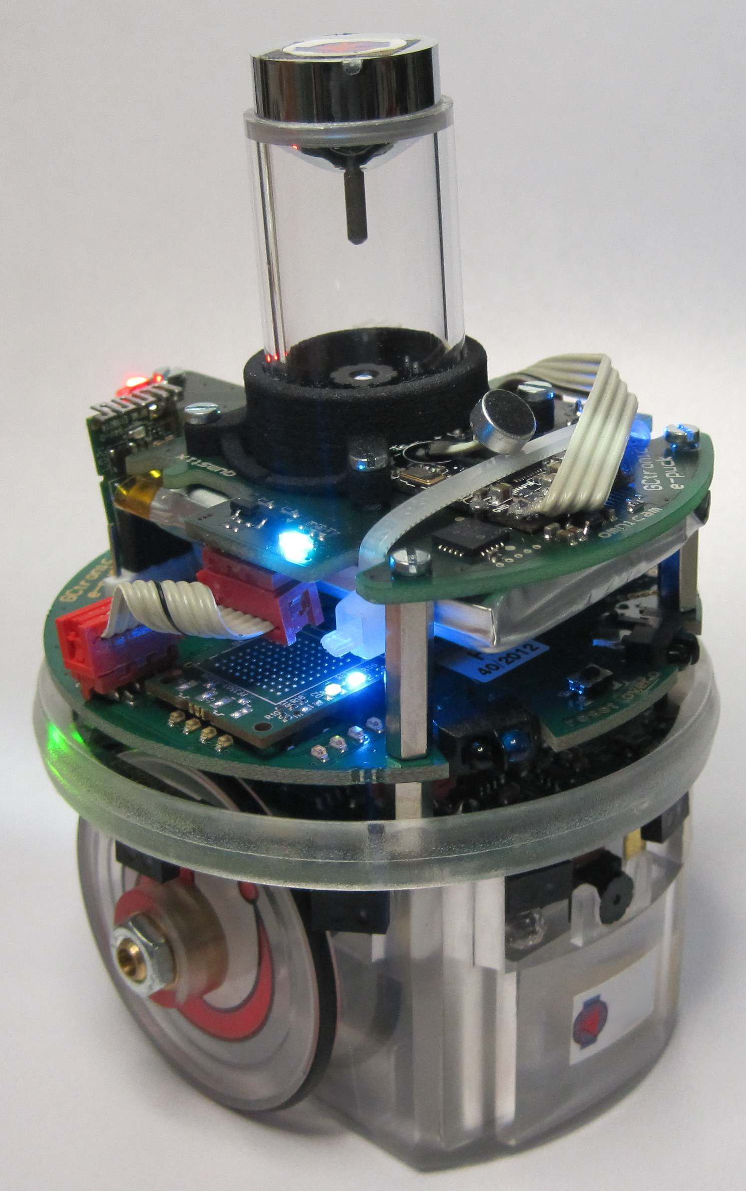
The omnivision module is upgraded with a microcontroller directly mounted on the extension that is responsible of handling the 3 RGB leds; the power of the leds can be set through I2C.
The camera mounted on the extension is an USB 2.0 camera with a maximum resolution of 1280x1024 and a potential framerate of 30 fps. Omnivision module may contain different image sensors depending on shipment date, in particular:
- the Targus Micro Webcam
- the Trust SpotLight Pro
The robot frontal camera below can still be used independently since this camera is connected either to the USB OTG or to the USB HOST of the e-puck gumstix extension.
The field of view is up to about 7 degrees over the horizon for the Trust SpotLight Pro, as shown in the following figure:
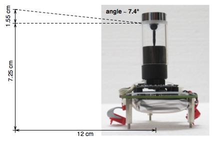
The same apply for the Targus camera as shown in the following figure:
1.1 Camera specification
| Name | Targus Micro Webcam AVC05EU | Trust SpotLight Pro |
| Supported resolutions | 1280x1024, 640x480, 352x288, 176x144, 160x120 | 1280x1024, 640x480, 352x288, 176x144, 160x120 |
| Maximum frame rate | 30 fps | 30 fps |
2 Getting started
2.1 1. Software
As with the gumstix extension, a specific firmware must be charged on the e-puck when working with this extension, it can be downloaded from section E-Puck#Standard_firmware. Remember to put the selector in position 10.
The system on the micro sd is the same used for the gumstix extension alone, refer to section https://www.gctronic.com/doc/index.php/Overo_Extension#File_system_image for more informations.
2.2 2. Terminal configuration
Execute a terminal program (e.g. minicom) and configure the connection with 115200-8N1. The serial device path should be typically something like "/dev/ttyUSB0". Make sure that the flow control parameter of minicom called "Hardware" is set to "No". Once the boot is terminated login with user=root and password=root.
2.3 3. WiFi
The nano WiFi dongle shipped with the extension board is an Edimax EW-7811Un, based on a Realtek chipset (RTL8192cu). The device isn't recognized automatically at boot, so you need to follow these steps in order to enable and use it:
- turn on the robot and login with user=root, password=root
- if the WiFi dongle is connected to the USB OTG you need to activate typing ./scripts/gumstix-common/usbenable otg
- type insmod 8192cu.ko (the kernel module is located in /home/root); the wifi dongle should be recognized and a wlanX device created
- type ifconfig wlanX up (where X is a number) to turn on the device; now the wifi can be configured and used normally
3 RGB leds
The RGB leds can be controlled from the gumstix-side through the I2C (400 KHz). The I2C address is 0x61 and to change the leds state all the values for each led need to be sent as follow: R1, G1, B1, R2, G2, B2, R3, G3, B3.
Once logged in it's possible to execute a demo to pilote all the 3 RGB leds through I2C:
- type ./demos/omnivision-v2/omnivision-i2c R1 G1 B1 R2 G2 B2 R3 G3 B3 where the Rx,Gx,Bx are the values you would like to set (ranging from 0 to 255)
You can download the source code from the following link omnivision-i2c-clean.c.
It was noticed that when the leds are turned on they can somehow create some reflex in the resulting image; in order to avoid this effect a simple solution would be to put a small piece of black tape on top of them.
Refer to the section https://www.gctronic.com/doc/index.php/Overo_Extension#3.3V_and_5V_source for more information about the RGB usage.
4 Camera
If the camera is connected to the USB OTG port you need to issue the following command to enable it (from /home/root/scripts/gumstix-common/ directory):
./usbenable otg
After this command a new device (/dev/video1) should be created automatically.
If the camera is connected to the USB HOST port then the camera is recognized automatically and the device /dev/video1 should be already available.
4.1 Image streaming
You can test and see the camera image using mjpeg-streamer; this tool is already configured with a web server in the system image so you can follow these steps:
- configure the network in order to be able to communicate between the gumstix and the computer
- issue the following commands:
export LD_LIBRARY_PATH=/usr/local/mjpg-streamer/:$LD_LIBRARY_PATH
/usr/local/mjpg-streamer/mjpg_streamer -i "input_uvc.so -y -d /dev/video1" -o "output_http.so -p 8090 -w /usr/local/mjpg-streamer/www"
- open a browser in the computer and insert the address https://gumstix-ip:8090 where gumstix-ip is the network address assigned to the gumstix
You can use also your phone to access the webserver.
The following figure shows an example of a 640x480 image received through the broswer:
For the post-processing of the image refers to the section https://www.gctronic.com/doc/index.php/Omnivision_Module#Image_unwrapping.
4.2 Image grabbing
4.2.1 Video 4 linux
The v4l2grab application can be used to grab an image from the camera with the following command:
./v4l2grab -d /dev/video1 -o image.jpg -f 1 -W 352 -H 288
Currently the maximum resolution is 352x288 from the OTG port, we're working to solve this limitation. From the USB HOST there is no known limitation.
4.2.2 OpenCV
An example demo was implemented to show how to interact with OpenCV and the Omnvision extension. In this demo a color blob is tracked; the target color range need to be passed as argument (HSV color space), the parameters in sequence are: Hmin Hmax Smin Smax Vmin Vmax debugFlag (values between 0 and 255, debugFlag = 0 or 1). The robot is rotated in place to track the detected blob.
You can download the source code from the following link blob-tracking-opencv.zip.
In order to build the code follow these steps:
- install the toolchain:
sudo apt-get install gcc-arm-linux-gnueabi g++-arm-linux-gnueabi - build using the makefile included in the zip file:
make
Before running the application you need to update some libraries on the gumstix system following these steps (this need to be done only once):
- configure the network in order to have internet access
- update the package manager repo:
echo 'src/gz base https://feeds.angstrom-distribution.org/feeds/v2012.12/ipk/eglibc/armv7a-vfp-neon/base/' > /etc/opkg/base-feed.conf - add
arch armv7a-vfp-neon 45to the file/etc/opkg/arch.conf opkg updateopkg install libc6opkg install libstdc++6- optionally you can also remove some warnings related to the update by running the following script remove-warnings.sh
Once the system is updated, you can copy the executable omniOpenCVblobDetection on the gumstix system and run it. Basically with the HSV range you define a target color, then once the application is started you can move the target around the robot and the robot should try to orient towards it.
4.3 Settings
You can modify the camera parameters to better suit your needs, here are the steps to install the v4l2-ctl utility for doing that:
- configure internet access
- make a copy of the current repo for the package source:
mv /etc/opkg/base-feed.conf /dest-dir - add the new repo:
echo 'src/gz base https://feeds.angstrom-distribution.org/feeds/unstable/ipk/glibc/armv7a/base' > /etc/opkg/base-feed.conf - issue the command
opkg update - place the file v4l-utils_0.8.1-r0.6_armv7a.ipk in the home directory and then issue:
opkg install v4l-utils_0.8.1-r0.6_armv7a.ipk
Once you install the utility, you can have a list of all available camera parameters by issueing the command v4l2-ctl -L.
For example to change the saturation you issue the command: v4l2-ctl --device=1 -c saturation=128
5 Charging
The omnivsion module incorporates an additional battery that can be charged with the e-puck battery charger, but it needs cabling (provided together with the extension) as illustrated in the following figures:
6 Extension firmware
The firmware programmed in the microcontroller mounted on the extension is freely available from the following link omnivision-uc-firmware.zip. The project is created with MPLAB IDE from Microchip.