|
|
| Line 1: |
Line 1: |
| =Overview=
| |
| <span class="plainlinks">[http://www.gctronic.com/doc/images/Elisa3_and_charger.JPG <img width=350 src="http://www.gctronic.com/doc/images/Elisa3_and_charger.JPG">]</span> <br/>
| |
| Elisa-3 is an evolution of the [http://www.gctronic.com/doc/index.php/Elisa Elisa] robot based on a different microcontroller and including a comprehensive set of sensors:
| |
| * [http://www.atmel.com/dyn/products/product_card.asp?part_id=3632 Atmel 2560] microcontroller (Arduino compatible)
| |
| * central RGB led
| |
| * 8 green leds around the robot
| |
| * IRs emitters
| |
| * 8 IR proximity sensors ([http://www.vishay.com/docs/83752/tcrt1000.pdf Vishay Semiconductors Reflective Optical Sensor])
| |
| * 4 ground sensors ([http://www.fairchildsemi.com/ds/QR/QRE1113.pdf Fairchild Semiconductor Minature Reflective Object Sensor])
| |
| * 3-axis accelerometer ([http://www.freescale.com/files/sensors/doc/data_sheet/MMA7455L.pdf Freescale MMA7455L])
| |
| * RF radio for communication ([http://www.nordicsemi.com/kor/Products/2.4GHz-RF/nRF24L01P Nordic Semiconductor nRF24L01+])
| |
| * micro USB connector for programming, debugging and charging
| |
| * IR receiver
| |
| * 2 DC motors
| |
| * top light diffuser
| |
| * selector
| |
| The robot is able to self charge using the charger station, as shown in the previous figure. The following figure illustrates the position of the various sensors: <br/>
| |
| <span class="plainlinks">[http://www.gctronic.com/doc/images/Elisa3-mainComp-digital-white.png <img width=400 src="http://www.gctronic.com/doc/images/Elisa3-mainComp-digital-white.png">]</span>
| |
|
| |
| ==Useful information==
| |
| * the top light diffuser and robot are designed to lock together, but the diffuser isn't fixed and can thus be removed as desired; the top light diffuser, as the name suggests, helps the light coming from the RGB led to be smoothly spread out, moreover the strip attached around the diffuser let the robot be better detected from others robots. Once the top light diffuser is removed, pay attention not to look at the RGB led directly. In order to remove the top light diffuser simply pull up it, then to place it back on top of the robot remember to align the 3 holes in the diffuser with the 3 IRs emitters and push down carefully untill the diffuser is stable; pay attention to not apply too much force on the IRs emitters otherwise they can bend and stop working.
| |
| <span class="plainlinks">[http://www.gctronic.com/doc/images/Diffuser-pull-up.jpg <img width=200 src="http://www.gctronic.com/doc/images/Diffuser-pull-up.jpg">]</span>
| |
| <span class="plainlinks">[http://www.gctronic.com/doc/images/Diffuser-push-down.jpg <img width=200 src="http://www.gctronic.com/doc/images/Diffuser-push-down.jpg">]</span><br/>
| |
| * when the top light diffuser is fit on top of the robot, then in order to change the selector position you can use the tweezers; the selector is located near the front-left IR emitter, as shown in the following figure:
| |
| <span class="plainlinks">[http://www.gctronic.com/doc/images/selector-tweezers.jpg <img width=200 src="http://www.gctronic.com/doc/images/selector-tweezers.jpg">]</span>
| |
| * if you encounter problems with the radio communication (e.g. lot of packet loss) then you can try moving the antenna that is a wire near the robot label. Place the antenna as high as possible, near the plastic top light diffuser; try placing it in the borders in order to avoid seeing a black line on the top light diffuser when the RGB led is turned on.
| |
| <span class="plainlinks">[http://www.gctronic.com/doc/images/Antenna-position.jpg <img width=200 src="http://www.gctronic.com/doc/images/Antenna-position.jpg">]</span>
| |
| <span class="plainlinks">[http://www.gctronic.com/doc/images/Antenna-diffuser.jpg <img width=200 src="http://www.gctronic.com/doc/images/Antenna-diffuser.jpg">]</span>
| |
|
| |
| ==Robot charging==
| |
| The Elisa-3 can be piloted in the charger station in order to be automatically self charged; there is no need to unplug the battery for charing. The following figures shows the robot approaching the charger station; a led indicates that the robot is in charge:
| |
| <br/>
| |
| <span class="plainlinks">[http://www.gctronic.com/doc/images/Elisa3-charger-out.jpg <img width=300 src="http://www.gctronic.com/doc/images/Elisa3-charger-out.jpg">]</span>
| |
| <span class="plainlinks">[http://www.gctronic.com/doc/images/Elisa3-charger-in.jpg <img width=350 src="http://www.gctronic.com/doc/images/Elisa3-charger-in.jpg">]</span> <br/>
| |
|
| |
| The microcontroller is informed when the robot is in charge and this information is also transferred to the PC in the ''flags'' byte; this let the user be able to pilote the robot to the charger station and be informed when it is actually in charge. More information about the radio protocol can be found in the section [http://www.gctronic.com/doc/index.php/Elisa-3#Communication Communication].
| |
|
| |
| Moreover the robot is also charged when the micro USB cable is connected to a computer; pay attention that if the USB cable is connected to a hub, this one need to be power supplied.
| |
|
| |
| The following video shows the Elisa-3 piloted through the radio to the charging station using the monitor application: {{#ev:youtube|kjliXlQcgzw}}
| |
|
| |
| ==Top light diffuser==
| |
| From February 2013 onwards the Elisa-3 is equipped with a new top light diffuser designed to fit perfectly in the 3 IRs emitters of the robot. The diffuser is made of plastic (3d printed), it is more robust and it simplifies the removal and insertion. Here is an image:<br/>
| |
| <span class="plainlinks">[http://www.gctronic.com/doc/images/elisa3-new-case.jpg <img width=350 src="http://www.gctronic.com/doc/images/elisa3-new-case-small.jpg">]</span>
| |
|
| |
| =Hardware= | | =Hardware= |
| The following figures show the main components offered by the Elisa-3 robot and where they are physically placed: <br/>
| | ==Overview== |
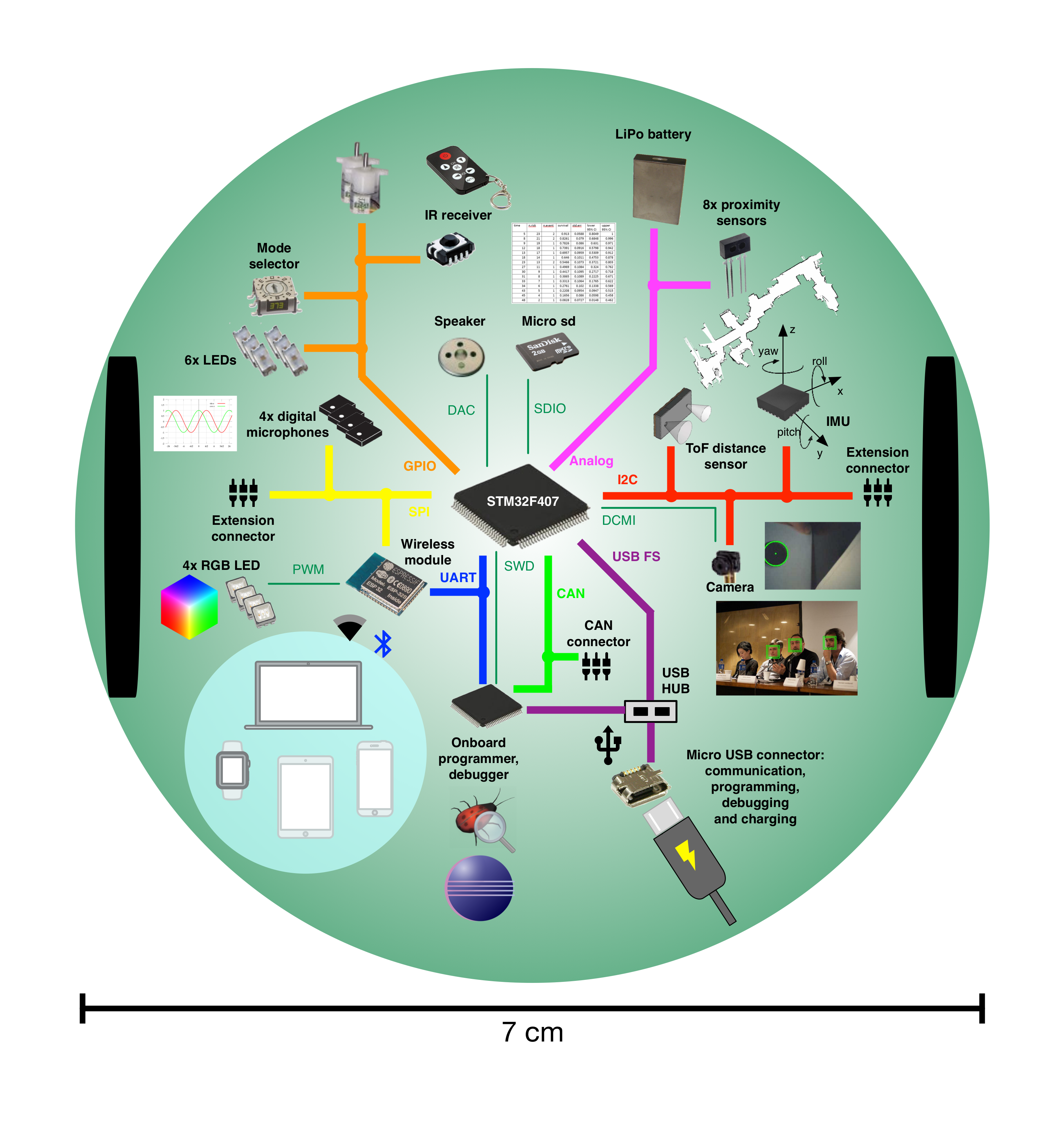
| <span class="plainlinks">[http://www.gctronic.com/doc/images/Elisa3.1-hw-schema-top.jpg <img width=550 src="http://www.gctronic.com/doc/images/Elisa3.1-hw-schema-top.jpg">]</span> <br/> | | <span class="plainlinks">[http://www.gctronic.com/doc/images/e-puck2-overview.png <img width=500 src="http://www.gctronic.com/doc/images/e-puck2-overview_small.png">]</span> |
| <span class="plainlinks">[http://www.gctronic.com/doc/images/Elisa3-hw-schema-bottom3.jpg <img width=400 src="http://www.gctronic.com/doc/images/Elisa3-hw-schema-bottom3.jpg">]</span> <br/> | | <span class="plainlinks">[https://projects.gctronic.com/epuck2/wiki_images/e-puck2-features.png <img width=600 src="https://projects.gctronic.com/epuck2/wiki_images/e-puck2-features_small.png">]</span><br/> |
|
| |
|
| ==Power autonomy==
| | The following figures show the main components offered by the e-puck2 robot and where they are physically placed:<br/> |
| The robot is equipped with two batteries for a duration of about 3 hours at normal usage (motors run continuously, IRs and RGB leds turned on). | | <span class="plainlinks">[https://projects.gctronic.com/epuck2/wiki_images/epuck2-components-position.png <img width=800 src="https://projects.gctronic.com/epuck2/wiki_images/epuck2-components-position_small.png">]</span><br/> |
| <span class="plainlinks">[http://www.gctronic.com/doc/images/Power-autonomy.jpg <img width=800 src="http://www.gctronic.com/doc/images/Power-autonomy.jpg">]</span> <br/> | |
|
| |
|
| ==Detailed specifications== | | ==Specifications== |
| | The e-puck2 robot maintains full compatibility with its predecessor e-puck (e-puck HWRev 1.3 is considered in the following table): |
| {| border="1" | | {| border="1" |
| |'''Feature''' | | |'''Feature''' |
| |'''Technical information''' | | |'''e-puck1.3''' |
| | |'''e-puck2''' |
| | |'''Compatibility''' |
| | |'''Additional''' |
| |- | | |- |
| |Size, weight | | |Size, weight |
| |50 mm diameter, 30 mm height, 39 g | | |70 mm diameter, 55 mm height, 150 g |
| | |Same form factor: 70 mm diameter, 45 mm, 130 g |
| | |style="text-align:center;" | <img width=40 src="http://www.gctronic.com/doc/images/ok.png"> |
| | |No e-jumper required |
| |- | | |- |
| |Battery, autonomy | | |Battery, autonomy |
| |LiIPo rechargeable battery (2 x 130 mAh, 3.7 V). About 3 hours autonomy. Recharging time about 1h e 30. | | |LiIPo rechargeable battery (external charger), 1800 mAh. <br/>About 3 hours autonomy. Recharging time about 2-3h. |
| | |Same battery; USB charging, recharging time about 2.5h. |
| | |style="text-align:center;" | <img width=30 src="http://www.gctronic.com/doc/images/plus.png"> |
| | |USB charging |
| |- | | |- |
| |Processor | | |Processor |
| |Atmel ATmega2560 @ 8MHz (~ 8 MIPS); 8 bit microcontroller | | |16-bit dsPIC30F6014A @ 60MHz (15 MIPS), DSP core for signal processing |
| | |32-bit STM32F407 @ 168 MHz (210 DMIPS), DSP and FPU, DMA |
| | |style="text-align:center;" | <img width=30 src="http://www.gctronic.com/doc/images/plus.png"> |
| | |~10 times faster |
| |- | | |- |
| |Memory | | |Memory |
| |RAM: 8 KB; Flash: 256 KB; EEPROM: 4 KB | | |RAM: 8 KB; Flash: 144 KB |
| | |RAM: 192 KB; Flash: 1024 KB |
| | |style="text-align:center;" | <img width=30 src="http://www.gctronic.com/doc/images/plus.png"> |
| | |RAM: 24x more capable<br/>Flash:~7x more capable |
| |- | | |- |
| |Motors | | |Motors |
| |2 DC motors with a 25:1 reduction gear; speed controlled with backEMF | | |2 stepper motors with a 50:1 reduction gear; 20 steps per revolution; about 0.13 mm resolution |
| | |Same motors |
| | |style="text-align:center;" | <img width=40 src="http://www.gctronic.com/doc/images/ok.png"> |
| | | |
| |- | | |- |
| |Magnetic wheels | | |Wheels |
| |Adesion force of about 1 N (100 g) depending on surface material and painting<br/> Wheels diamater = 9 mm <br/>Distance between wheels = 40.8 mm | | |Wheels diamater = 41 mm <br/>Distance between wheels = 53 mm |
| | |Same wheels |
| | |style="text-align:center;" | <img width=40 src="http://www.gctronic.com/doc/images/ok.png"> |
| | | |
| |- | | |- |
| |Speed | | |Speed |
| |Max: 60 cm/s | | |Max: 1000 steps/s (about 12.9 cm/s) |
| | |Max: 1200 steps/s (about 15.4 cm/s) |
| | |style="text-align:center;" | <img width=30 src="http://www.gctronic.com/doc/images/plus.png"> |
| | |20% faster |
| |- | | |- |
| |Mechanical structure | | |Mechanical structure |
| |PCB, motors holder, top white plastic to diffuse light | | |Transparent plastic body supporting PCBs, battery and motors |
| | |Same mechanics |
| | |style="text-align:center;" | <img width=40 src="http://www.gctronic.com/doc/images/ok.png"> |
| | | |
| | |- |
| | |Distance sensor |
| | |8 infra-red sensors measuring ambient light and proximity of objects up to 6 cm |
| | |Same infra-red sensors <br/>Front real distance sensor, Time of fight (ToF), up to 2 meter. |
| | |style="text-align:center;" | <img width=30 src="http://www.gctronic.com/doc/images/plus.png"> |
| | |ToF sensor |
| |- | | |- |
| |IR sensors | | |IMU |
| |8 infra-red sensors measuring ambient light and proximity of objects up to 6 cm; each sensor is 45° away from each other <br/> 4 ground sensors detecting the end of the viable surface (placed on the front-side of the robot) | | |3D accelerometer and 3D gyro |
| | |3D accelerometer, 3D gyro, 3D magnetometer |
| | |style="text-align:center;" | <img width=30 src="http://www.gctronic.com/doc/images/plus.png"> |
| | |3D magnetometer |
| |- | | |- |
| | IR emitters | | |Camera |
| | 3 IR emitters (2 on front-side, 1 on back-side of the robot) | | |VGA color camera; typical use: 52x39 or 480x1 |
| | |Same camera; typical use: 160x120 |
| | |style="text-align:center;" | <img width=40 src="http://www.gctronic.com/doc/images/ok.png"> |
| | |Bigger images handling |
| |- | | |- |
| |Accelerometer | | |Audio |
| |3D accelerometer along the X, Y and Z axis | | |3 omni-directional microphones for sound localization<br/>speaker capable of playing WAV or tone sounds |
| | |4 omni-directional microhpones (digital) for sound localization<br/>speaker capable of playing WAV or tone sounds |
| | |style="text-align:center;" | <img width=30 src="http://www.gctronic.com/doc/images/plus.png"> |
| | | +1 front microphone |
| |- | | |- |
| |LEDs | | |LEDs |
| |1 RGB LED in the center of the robot; 8 green LEDs around the robot | | |8 red LEDs around the robot, green body light, 1 strong red LED in front |
| | |4 red LEDs and 4 RGB LEDs around the robot, green light, 1 strong red LED in front |
| | |style="text-align:center;" | <img width=30 src="http://www.gctronic.com/doc/images/plus.png"> |
| | |4x RGB LEDs |
| |- | | |- |
| |Switch / selector | | |Communication |
| |16 position rotating switch | | |RS232 and Bluetooth 2.0 for connection and programming |
| | |USB Full-speed, Bluetooth 2.0, BLE, WiFi |
| | |style="text-align:center;" | <img width=30 src="http://www.gctronic.com/doc/images/plus.png"> |
| | |WiFi, BLE |
| |- | | |- |
| |Communication | | |Storage |
| | Standard Serial Port (up to 38kbps)<br/> Wireless: RF 2.4 GHz; the throughput depends on number of robot: eg. 250Hz for 4 robots, 10Hz for 100 robots; up to 10 m | | |Not available |
| | |Micro SD slot |
| | |style="text-align:center;" | <img width=30 src="http://www.gctronic.com/doc/images/plus.png"> |
| | |Micro SD |
| |- | | |- |
| |Remote Control | | |Remote Control |
| |Infra-red receiver for standard remote control commands | | |Infra-red receiver for standard remote control commands |
| | |Same receiver |
| | |style="text-align:center;" | <img width=40 src="http://www.gctronic.com/doc/images/ok.png"> |
| | | |
| | |- |
| | |Switch / selector |
| | |16 position rotating switch |
| | |Same selector |
| | |style="text-align:center;" | <img width=40 src="http://www.gctronic.com/doc/images/ok.png"> |
| | | |
| |- | | |- |
| |Expansion bus | | |Extensions |
| |Optional connectors: 2 x UART, I2C, 2 x PWM, battery, ground, analog and digital voltage | | |Ground sensors, range and bearing, RGB panel, Gumstix extension, omnivision, your own |
| | |All extension supported |
| | |style="text-align:center;" | <img width=40 src="http://www.gctronic.com/doc/images/ok.png"> |
| | | |
| |- | | |- |
| |Programming | | |Programming |
| |C/C++ programming with the AVR-GCC compiler ([http://winavr.sourceforge.net/ WinAVR] for Windows). Free compiler and IDE (AVR Studio / Arduino) | | |Free C compiler and IDE, Webots simulator, external debugger |
| |} | | |Free C compiler and IDE, Webots simulator, onboard debugger (GDB) |
| | | |style="text-align:center;" | <img width=30 src="http://www.gctronic.com/doc/images/plus.png"> |
| =Communication= | | |Onboard debugger |
| ==Wireless==
| |
| The radio base-station is connected to the PC through USB and transfers data to and from the robot wirelessly. In the same way the radio chip ([http://www.nordicsemi.com/eng/Products/2.4GHz-RF/nRF24L01P nRF24L01+]) mounted on the robot communicates through SPI with the microcontroller and transfers data to and from the PC wirelessly.<br/>
| |
| The robot is identified by an address that is stored in the last two bytes of the microcontroller internal EEPROM; the robot firmware setup the radio module reading the address from the EEPROM. This address corresponds to the robot id written on the label placed under the robot and should not be changed.<br/>
| |
| <span class="plainlinks">[http://www.gctronic.com/doc/images/Elisa-communication.jpg <img width=400 src="http://www.gctronic.com/doc/images/Elisa-communication.jpg">]</span><br/>
| |
| | |
| ===Packet format - PC to radio to robot===
| |
| The 13 bytes payload packet format is shown below (the number in the parenthesis expresses the bytes):
| |
| {| border="1"
| |
| | Command (1)
| |
| | Red led (1)
| |
| | Blue led (1)
| |
| | Green led (1)
| |
| | IR + Flags (1)
| |
| | Right motor (1)
| |
| | Left motor (1)
| |
| | Small green leds (1)
| |
| | Flags2 (1)
| |
| | Remaining 5 bytes are unused | |
| |} | | |} |
|
| |
|
| * Command: 0x27 = change robot state; 0x28 = goto base-station bootloader (this byte is not sent to the robot)
| | This is the overall communication schema:<br/> |
| * Red, Blue, Green leds: values from 0 (OFF) to 100 (ON max power)
| | <span class="plainlinks">[http://www.gctronic.com/doc/images/comm-overall-e-puck2E.jpg <img width=700 src="http://www.gctronic.com/doc/images/comm-overall-e-puck2E.jpg">]</span><br/> |
| * IR + flags:
| |
| ** first two bits are dedicated to the IRs:
| |
| *** 0x00 => all IRs off
| |
| *** 0x01 => back IR on
| |
| *** 0x02 => front IRs on
| |
| *** 0x03 => all IRs on
| |
| ** third bit is reserved for enabling/disabling IR remote control (0=>disabled, 1=>enabled)
| |
| ** fourth bit is used for sleep (1 => go to sleep for 1 minute)
| |
| ** fifth bit is used to calibrate all sensors (proximity, ground, accelerometer) and reset odometry
| |
| ** sixth bit is reserved (used by radio station)
| |
| ** seventh bit is used for enabling/disabling onboard obstacle avoidance
| |
| ** eight bit is used for enabling/disabling onboard cliff avoidance
| |
| * Right, Left motors: speed expressed in 1/5 of mm/s (i.e. a value of 10 means 50 mm/s); MSBit indicate direction: 1=forward, 0=backward; values from 0 to 127
| |
| * Small green leds: each bit define whether the corresponding led is turned on (1) or off (0); e.g. if bit0=1 then led0=on
| |
| * Flags2:
| |
| ** bit0 is used for odometry calibration
| |
| ** remaining bits unused
| |
| * Remaining bytes free to be used
| |
| | |
| ====Optimized protocol====
| |
| The communication between the pc and the base-station is controlled by the master (computer) that continuously polls the slave (base-station); the polling is done once every millisecond and this is a restriction on the maximum communication throughput. To overcome this limitation we implemented an optimized protocol in which the packet sent to the base-station contains commands for four robots simultaneously; the base-station then separate the data and send them to the correct robot address. The same is applied in reception, that is the base-station is responsible of receiving the ack payloads of 4 robots (64 bytes in total) and send them to the computer. This procedure let us have a throughput 4 times faster.
| |
| <!-- | |
| - ack returned must be up to 16 bytes (max 64 bytes for the usb buffer); the same number of bytes returned by the robot as ack payload has to be read then by the pc!!
| |
| - la base-station ritorna "2" quando l'ack non è stato ricevuto;
| |
| -->
| |
| | |
| ===Packet format - robot to radio to PC===
| |
| The robot send back to the base-station information about all its sensors every time it receive a command; this is accomplished by using the "ack payload" feature of the radio module. Each "ack payload" is 16 bytes length and is marked with an ID that is used to know which information the robot is currently transferring. The sequence is the following (the number in the parenthesis expresses the bytes):
| |
| {| border="1"
| |
| |ID=3 (1)
| |
| |Prox0 (2)
| |
| |Prox1 (2)
| |
| |Prox2 (2)
| |
| |Prox3 (2)
| |
| |Prox5 (2)
| |
| |Prox6 (2)
| |
| |Prox7 (2)
| |
| |Flags (1)
| |
| |-
| |
| |||||||||||||||||
| |
| |-
| |
| |ID=4 (1)
| |
| |Prox4 (2)
| |
| |Ground0 (2)
| |
| |Ground1 (2)
| |
| |Ground2 (2)
| |
| |Ground3 (2)
| |
| |AccX (2)
| |
| |AccY (2)
| |
| |TV remote (1)
| |
| |-
| |
| |||||||||||||||||
| |
| |-
| |
| |ID=5 (1)
| |
| |ProxAmbient0 (2)
| |
| |ProxAmbient1 (2)
| |
| |ProxAmbient2 (2)
| |
| |ProxAmbient3 (2)
| |
| |ProxAmbient5 (2)
| |
| |ProxAmbient6 (2)
| |
| |ProxAmbient7 (2)
| |
| |Selector (1)
| |
| |-
| |
| |||||||||||||||||
| |
| |-
| |
| |ID=6 (1)
| |
| |ProxAmbient4 (2)
| |
| |GroundAmbient0 (2)
| |
| |GroundAmbient1 (2)
| |
| |GroundAmbient2 (2)
| |
| |GroundAmbient3 (2)
| |
| |AccZ (2)
| |
| |Battery (2)
| |
| |Free (1)
| |
| |-
| |
| |||||||||||||||||
| |
| |-
| |
| |ID=7 (1)
| |
| |LeftSteps (4)
| |
| |RightSteps (4)
| |
| |theta (2)
| |
| |xpos (2)
| |
| |ypos (2)
| |
| |Free (1)
| |
| |
| |
| |
| |
| |}
| |
| | |
| Pay attention that the base-station could return "error" codes in the first byte if the communication has problems:
| |
| * 0 => transmission succeed (no ack received though)
| |
| * 1 => ack received (should not be returned because if the ack is received, then the payload is read)
| |
| * 2 => transfer failed
| |
| | |
| Packet ID 3:
| |
| * Prox* contain values from 0 to 1023, the greater the values the nearer the objects to the sensor
| |
| * The ''Flags'' byte contains these information:
| |
| ** bit0: 0 = robot not in charge; 1 = robot in charge
| |
| ** bit1: 0 = button pressed; 1 = button not pressed
| |
| ** bit2: 0 = robot not charged completely; 1 = robot charged completely
| |
| ** the remainig bits are not used at the moment
| |
| | |
| Packet ID 4:
| |
| * Prox4 contains values from 0 to 1023, the greater the values the nearer the objects to the sensor
| |
| * Ground* contain values from 512 to 1023, the smaller the value the darker the surface
| |
| * AccX and AccY contain raw values of the accelerometer; the range is between -64 to 64
| |
| * TV remote contains the last interpreted command received through IR
| |
| | |
| Packet ID 5:
| |
| * ProxAmbient* contain values from 0 to 1023, the smaller the values the brighter the ambient light
| |
| * Selector contains the value of the current selector position
| |
| | |
| Packet ID 6:
| |
| * ProxAmbient4 contains values from 0 to 1023, the smaller the values the brighter the ambient light
| |
| * GroundAmbient* contain values from 0 to 1023, the smaller the values the brighter the ambient light
| |
| * AccZ contains raw values of the accelerometer; the range is between 0 and -128 (upside down)
| |
| * Battery contains the sampled value of the battery, the values range is between 780 (battery discharged) and 930 (battery charged)
| |
| | |
| Packet ID 7:
| |
| * LeftSteps and RightSteps contain the sum of the sampled speed for left and right motors respectively (only available when the speed controller isn't used; refer to xpos, ypos and theta when the speed controller is used)
| |
| * theta contains the orientation of the robot expressed in 1/10 of degree (3600 degrees for a full turn); available only when the speed controller is enabled
| |
| * xpos and ypos contain the position of the robot expressed in millimeters; available only when the speed controller is enabled
| |
| | |
| ==USB cable==
| |
| You can directly connect the robot to the computer to make a basic functional test. You can find the source code in the following link [https://projects.gctronic.com/elisa3/Elisa3-global-test.zip Elisa3-global-test.zip] (Windows).<br/>
| |
| To start the test follow these steps:
| |
| # put the selector in position 6
| |
| # connect the robot to the computer with the USB cable and turn it on
| |
| # run the program, insert the correct COM port and choose option 1
| |
| With the same program you can also change the ID of the robot by choosing option 2 in the last step (not recommended).
| |
| | |
| Via USB cable you can also program the robot with [https://www.gctronic.com/doc/index.php?title=Elisa-3#Aseba Aseba].
| |
| | |
| =Software= | |
| | |
| ==Robot==
| |
| ===Requirements===
| |
| In order to communicate with the robot through the micro USB the FTDI driver need to be installed. If a serial port is automatically created when connecting the robot to the computer you're done otherwise you need to download the drivers for your system and architecture:
| |
| * [http://www.ftdichip.com/Drivers/CDM/CDM%20v2.10.00%20WHQL%20Certified.exe Windows Vista/XP], [http://www.ftdichip.com/Drivers/CDM/CDM%20v2.12.10%20WHQL%20Certified.exe Windows 7/8/10 (run as administrator)]
| |
| * Ubuntu: when the robot is connected the port will be created in <code>/dev/ttyUSB0</code> (no need to install a driver)
| |
| * [http://www.ftdichip.com/drivers/VCP/MacOSX/FTDIUSBSerialDriver_v2_2_18.dmg Mac OS X 10.3 to 10.8 (32 bit)], [http://www.ftdichip.com/Drivers/VCP/MacOSX/FTDIUSBSerialDriver_v2_2_18.dmg Mac OS X 10.3 to 10.8 (64 bit)], [http://www.ftdichip.com/Drivers/VCP/MacOSX/FTDIUSBSerialDriver_v2_3.dmg Mac OS X 10.9 and above]; after installing the driver the port will be created in <code>/dev/tty.usbserial-...</code>; you can find a guide on how to install the driver in the following link [http://www.ftdichip.com/Support/Documents/AppNotes/AN_134_FTDI_Drivers_Installation_Guide_for_MAC_OSX.pdf AN_134_FTDI_Drivers_Installation_Guide_for_MAC_OSX.pdf]
| |
| All the drivers can be found in the official page from the following link [http://www.ftdichip.com/Drivers/VCP.htm FTDI drivers].
| |
|
| |
|
| ===AVR Studio 4 project=== | | ==Documentation== |
| The projects are built with [https://projects.gctronic.com/elisa3/AvrStudio4Setup.exe AVR Studio 4] released by Atmel. <br/>
| | * '''Main microcontroller''': STM32F407, [https://projects.gctronic.com/epuck2/doc/STM32F407xx_datasheet.pdf datasheet], [https://projects.gctronic.com/epuck2/doc/STM32F407_reference-manual.pdf reference-manual] |
| The projects should be compatible also with newer versions of Atmel Studio, the last version is available from [https://www.microchip.com/mplab/avr-support/avr-and-sam-downloads-archive https://www.microchip.com/mplab/avr-support/avr-and-sam-downloads-archive]. <br/>
| | * '''Programmer/debugger''': STM32F413, [https://projects.gctronic.com/epuck2/doc/STM32F413x_datasheet.pdf datasheet], [https://projects.gctronic.com/epuck2/doc/STM32F413_reference-manual.pdf reference-manual] |
| | * '''Radio module''': Espressif ESP32, [https://projects.gctronic.com/epuck2/doc/esp32_datasheet_en.pdf datasheet], [https://projects.gctronic.com/epuck2/doc/esp32_technical_reference_manual_en.pdf reference-manual] |
| | * '''Camera''': PixelPlus PO8030D CMOS image sensor, [https://projects.gctronic.com/E-Puck/docs/Camera/PO8030D.pdf datasheet], no IR cut filter |
| | : From about July 2019, the camera mounted on the e-puck2 robot is the Omnivision OV7670 CMOS image sensor, [https://projects.gctronic.com/epuck2/doc/OV7670.pdf datasheet] |
| | * '''Microphones''': STM-MP45DT02, [https://projects.gctronic.com/epuck2/doc/mp45dt02.pdf datasheet] |
| | * '''Optical sensors''': Vishay Semiconductors Reflective Optical Sensor, [https://projects.gctronic.com/epuck2/doc/tcrt1000.pdf datasheet] |
| | * '''ToF distance sensor''': STM-VL53L0X, [https://projects.gctronic.com/epuck2/doc/VL53L0X-Datasheet.pdf datasheet], [https://projects.gctronic.com/epuck2/doc/VL53L0X-UserManual-API.pdf user-manual] |
| | * '''IMU''': InvenSense MPU-9250, [https://projects.gctronic.com/epuck2/doc/MPU-9250-product-specification.pdf product-specification], [https://projects.gctronic.com/epuck2/doc/MPU-9250-Register-Map.pdf register-map] |
| | * '''Motors''': [http://www.e-puck.org/index.php?option=com_content&view=article&id=7&Itemid=9 details] |
| | * '''Speaker''': Diameter 13mm, power 500mW, 8 Ohm, DS-1389 or PSR12N08AK or similar |
| | * '''IR receiver''': TSOP36230 |
|
| |
|
| ====Basic demo==== | | ==Migrating from e-puck1.x to e-puck2== |
| This project is thought to be a starting point for Elisa-3 newbie users and basically contains a small and clean main with some basic demos selected through the hardware selector that show how to interact with robot sensors and actuators.
| | The e-puck2 robot maintains full compatibility with its predecessor e-puck, but there are some improvements that you should be aware of.<br/> |
| The project source can be downloaded from the repository [https://github.com/gctronic/elisa3_firmware_basic https://github.com/gctronic/elisa3_firmware_basic]; the hex file can be directly downloaded from [https://projects.gctronic.com/elisa3/elisa3-firmware-basic_ffb3947_21.03.18.hex Elisa-3 basic firmware hex]. To program the robot refer to section [http://www.gctronic.com/doc/index.php/Elisa-3#Programming Programming]. <br/>
| |
| Selector position and related demo:
| |
| * 0: no speed controller activated => free running (all others positions have the speed controller activated)
| |
| * 1: obstacle avoidance enabled
| |
| * 2: cliff avoidance enabled (currently it will simply stop before falling and stay there waiting for commands)
| |
| * 3: both obstacle and cliff avoidance enabled
| |
| * 4: random RGB colors and small green leds on
| |
| * 5: robot moving forward with obstacle avoidance enabled and random RGB colors
| |
|
| |
|
| ====Advanced demo====
| | First of all the e-jumper, that is the small board that is attached on top of the e-puck1.x, isn't anymore needed in the e-puck2. The components available on the e-jumper are integrated directly in the robot board. On top of the e-puck2 you'll see a quite big free connector, this is used to attach the extensions board designed for the e-puck1.x that are fully compatible with the e-puck2; you must not connect the e-jumper in this connector.<br/> |
| This is an extension of the ''basic demo project'', basically it contains some additional advanced demos.
| | |
| The project source can be downloaded from the repository [https://github.com/gctronic/elisa3_firmware_advanced.git https://github.com/gctronic/elisa3_firmware_advanced.git]; the hex file can be directly downloaded from [https://projects.gctronic.com/elisa3/elisa3-firmware-advanced_96c355a_13.03.18.hex Elisa-3 advanced firmware hex]. To program the robot refer to section [http://www.gctronic.com/doc/index.php/Elisa-3#Programming Programming]. <br/> | | Secondly you don't need anymore to unplug and plugin the battery for charging, but instead you can charge the battery (up to 1 ampere) directly by connecting the USB cable. If you want you can still charge the battery with the e-puck1.x external charger, in case you have more than one battery.<br/> |
| Selector position and related demo:
| |
| * 0: no speed controller activated => free running (all others positions have the speed controller activated)
| |
| * 1: obstacle avoidance enabled
| |
| * 2: cliff avoidance enabled (currently it will simply stop before falling and stay there waiting for commands)
| |
| * 3: both obstacle and cliff avoidance enabled
| |
| * 4: random RGB colors and small green leds on
| |
| * 5: robot moving forward with obstacle avoidance enabled and random RGB colors
| |
| * 6: robot testing and address writing through serial connection (used in production)
| |
| * 7: automatic charging demo (refer to section [http://www.gctronic.com/doc/index.php/Elisa-3#Videos Videos]), that is composed of 4 states:
| |
| ** random walk with obstacle avoidance
| |
| ** search black line
| |
| ** follow black line that lead to the charging station
| |
| ** charge for a while
| |
| * 8: autonomous odometry calibration (refer to section [http://www.gctronic.com/doc/index.php/Elisa-3#Autonomous_calibration Autonomous calibration])
| |
| * 9: write default odometry calibration values in EEPROM (hard-coded values); wait 2 seconds before start writing the calibration values
| |
| * 10: robot moving forward (with pause) and obstacle avoidance enabled; random RGB colors and green led effect
| |
| * 11: local communication: robot alignment
| |
| * 12: local communication: 2 or more robots exchange data sequentially
| |
| * 13: local communication: listen and transmit continuously; when data received change RGB color
| |
| * 14: local communication: RGB color propagation
| |
| * 15: clock calibration (communicate with the PC through the USB cable to change the OSCCAL register); this position could also be used to remote contol the robot through the radio (only speed control is enabled)
| |
|
| |
|
| ====Atmel Studio 7====
| | Moreover you don't need anymore a special serial cable (with probably an RS232 to USB adapter) to be able to communicate with the robot, but you can use the USB cable. Once connected to the computer a serial port will be available that you can use to easily exchange data with the robot. |
| If you are working with Atmel Studio 7, you can simply use the provided AVR Studio 4 projects by importing them directly in Atmel Studio 7: <code>File => Import => AVR Studio 4 Project</code>, then select <code>Elisa3-avr-studio.aps</code> and click on <code>Convert</code>.
| |
|
| |
|
| ===Arduino IDE project=== | | ==Extensions== |
| The project is built with the Arduino IDE 1.x freely available from the [http://arduino.cc/ official Arduino website]. In order to build the Elisa-3 firmware with the Arduino IDE 1.x the following steps has to be performed:<br/>
| | All the extensions (ground sensors, range and bearing, RGB panel, gumstix and omnvision) are supported by the e-puck2 robot, this means that if you have some extensions for the e-puck1.x you can still use them also with e-puck2.<br/> |
| *1. download the [http://arduino.cc/hu/Main/Software Arduino IDE 1.x] (the last known working version is 1.8.9, refer to [https://www.arduino.cc/en/Main/OldSoftwareReleases#previous Arduino Software]) and extract it, let say in a folder named <code>arduino-1.x</code><br/>
| | For more information about using the gumstix extension with e-puck2 robot refer to [http://www.gctronic.com/doc/index.php?title=Overo_Extension#e-puck2 http://www.gctronic.com/doc/index.php?title=Overo_Extension#e-puck2]. |
| *2. download the [https://projects.gctronic.com/elisa3/elisa3_arduino_library_13.03.18_691e478.zip Elisa-3 library] and extract it within the libraries folder of the Arduino IDE, in this case <code>arduino-1.x\libraries</code>; you should end up with a <code>Elisa3</code> folder within the libraries. If you start the Arduino IDE now you can see that the <code>Elisa-3</code> library is available in the menu <code>Sketch=>Import Library...</code> (or <code>Sketch=>Include Lirary</code> in later IDE versions)<br/>
| |
| *3. the file <code>boards.txt</code> in the Arduino IDE folder <code>arduino-1.x\hardware\arduino</code> (or <code>arduino-1.x\hardware\arduino\avr</code> in later IDE versions) need to be changed to contain the definitions for the Elisa-3 robot, add the following definitions at the end of the file:
| |
| <pre>
| |
| ##############################################################
| |
|
| |
|
| elisa3.name=Elisa 3 robot
| | =Getting Started= |
| | The e-puck2 robot features 3 chips onboard: |
| | * the main microcontroller, that is responsible for handling the sensors and actuators and which runs also the demos/algorithms |
| | * the programmer, that provides programming/debugging capabilties and moreover it configures the USB hub and is responsible for the power management (on/off of the robot and battery measure) |
| | * radio module, that is responsible for handling the wireless communication (WiFi, BLE, BT), the RGB LEDs and the user button (the RGB LEDs and button are connected to the radio module due to the pin number limitation on the main microcontroller) |
|
| |
|
| elisa3.upload.tool=avrdude
| | The robot is shipped with the last firmware version programmed on all 3 chips, so you can immediately start using the robot.<br/> |
| elisa3.upload.protocol=stk500v2
| | The following sections explain the basic usage of the robot, <b>all the users should read this chapter completely in order to have a minimal working system ready to play with the e-puck2 robot</b>. Some sections will have more detailed information that can be read by following the links provided. |
| elisa3.upload.maximum_size=258048
| |
| elisa3.upload.speed=57600
| |
|
| |
| elisa3.bootloader.low_fuses=0xE2
| |
| elisa3.bootloader.high_fuses=0xD0
| |
| elisa3.bootloader.extended_fuses=0xFF
| |
| elisa3.bootloader.path=stk500v2-elisa3
| |
| elisa3.bootloader.file=stk500v2-elisa3.hex
| |
| elisa3.bootloader.unlock_bits=0x3F
| |
| elisa3.bootloader.lock_bits=0x0F
| |
|
| |
|
| elisa3.build.mcu=atmega2560
| | When required, dedicated informations are given for all platforms (Windows, Linux, Mac). The commands given for Linux are related to the Ubuntu distribution, similar commands are available in other distributions. |
| elisa3.build.f_cpu=8000000L
| |
| elisa3.build.board=AVR_ELISA3
| |
| elisa3.build.core=arduino
| |
| elisa3.build.variant=mega
| |
|
| |
|
| ##############################################################
| | ==Turn on/off the robot== |
| </pre>
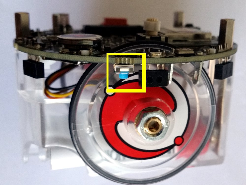
| | To turn on the robot you need to press the power button (blue button) placed on the bottom side of the board, near the speaker, as shown in the following figures: |
| *4. this step need to be performed only with later IDE versions, when you receive a warning like this <code>Bootloader file specified but missing...</code> during compilation.<br/> In this case place the bootloader hex file (<code>stk500v2.hex</code>) you can find in the [http://www.gctronic.com/doc/index.php/Elisa-3#Bootloader Bootloader section] in the directory <code>arduino-1.x\Arduino\hardware\arduino\avr\bootloaders\</code> and name it <code>stk500v2-elisa3.hex</code>
| | ::<span class="plain links">[https://projects.gctronic.com/epuck2/wiki_images/e-puck2-btn-on-off2.jpg <img width=250 src="https://projects.gctronic.com/epuck2/wiki_images/e-puck2-btn-on-off2-small.jpg">][https://projects.gctronic.com/epuck2/wiki_images/e-puck2-btn-on-off.jpg <img width=300 src="https://projects.gctronic.com/epuck2/wiki_images/e-puck2-btn-on-off-small.jpg">]</span><br/> |
| *5. download the [https://projects.gctronic.com/elisa3/elisa3_arduino_project_02.03.21_d2c017e.zip Elisa-3 project file] and open it with the Arduino IDE (you should open the file "''elisa3.ino''")
| | To turn off the robot you need to press the power button for 1 second. |
| *6. select <code>Elisa-3 robot</code> from the <code>Tools=>Board</code> menu; click on the <code>Verify</code> button to build the project
| |
| *7. to upload the resulting hex file, attach the micro usb and set the port from the <code>Tools=>Serial Port</code> menu consequently; turn on the robot and click on the <code>Upload</code> button
| |
|
| |
|
| You can download the Arduino IDE 1.0.5 for Linux (32 bits) containing an updated avr toolchain (4.5.3) and the Elisa3 library from the following link [https://projects.gctronic.com/elisa3/arduino-1.0.5-linux32.zip arduino-1.0.5-linux32.zip]. <br/>
| | ==Meaning of the LEDs== |
| If the <code>Tools->Serial Port</code> menu is grayed out then you need to start the Arduino IDE in a terminal typing <code>sudo path/to/arduino</code>.<br/>
| | The e-puck2 has three groups of LEDs that are not controllable by the user. |
|
| |
|
| If you want to have access to the compiler options you can download the following project [https://projects.gctronic.com/elisa3/Elisa3-arduino-makefile.zip Elisa3-arduino-makefile.zip] that contains an Arduino IDE project with a Makefile, follow the instructions in the "readme.txt" file in order to build and upload to the robot.
| | ::<span class="plain links">[https://projects.gctronic.com/epuck2/wiki_images/e-puck2_top_leds.png <img width=250 src="https://projects.gctronic.com/epuck2/wiki_images/e-puck2_top_leds.png">]</span><br/> |
| | ::''Top view of the e-puck2'' |
|
| |
|
| ===Aseba===
| | *Charger: RED if charging, GREEN if charge complete and RED and GREEN if an error occurs |
| Refer to the page [{{fullurl:Elisa-3 Aseba}} Elisa-3 Aseba].
| | *USB: Turned ON if the e-puck2 detects a USB connection with a computer |
| | *STATUS: Turned ON if the robot is ON and OFF if the robot is OFF. When ON, gives an indication of the level of the battery. Also blinks GREEN if the program is running during a debug session. |
|
| |
|
| ===Matlab===
| | Battery level indications (STATUS RGB LED): |
| <span class="plainlinks">[http://www.gctronic.com/doc/images/elisa3-matlab.jpg <img width=200 src="http://www.gctronic.com/doc/images/elisa3-matlab-small.jpg">]</span><br/>
| | *GREEN if the system's tension is greater than 3.5V |
| The [http://www.e-puck.org/index.php?option=com_content&view=article&id=29&Itemid=27 ePic2] Matlab interface was adapted to work with the Elisa-3 robot. The communication is handled with the radio module. Both Matlab 32 bits and 64 bits are supported (tested on Matlab R2010a). Follow these steps to start playing with the interface:
| | *ORANGE if the system's tension is between 3.5V and 3.4V |
| # program the robot with the [http://www.gctronic.com/doc/index.php/Elisa-3#Advanced_demo advanced demo]
| | *RED if the system's tension is between 3.4V and 3.3V |
| # place the selector in position 15 (to pilot the robot through the interface with no obstacle and no cliff avoidance)
| | *RED blinking if the system's tension is below 3.3V |
| # connect the radio base-station to the computer
| |
| # download the ePic2 for Elisa-3 from the repository [https://github.com/gctronic/elisa3_epic.git https://github.com/gctronic/elisa3_epic.git]: either from github site clicking on <code>Code</code>=><code>Download ZIP</code> or by issueing the command <code>git clone https://github.com/gctronic/elisa3_epic.git</code>
| |
| # open (double click) the file ''main.m''; once Matlab is ready type ''main+ENTER'' and the GUI should start
| |
| # click on the ''+'' sign (top left) and insert the robot address (e.g 3307), then click on ''Connect''
| |
|
| |
|
| ===Webots simulator===
| | The robot is automatically turned OFF if the system's tension gets below 3.2V during 10 seconds. |
| <span class="plainlinks">[http://www.gctronic.com/doc/images/Elisa-3-webots.png <img width=200 src="http://www.gctronic.com/doc/images/Elisa-3-webots-small.png">]</span><br/>
| |
| The following features have been included in the Elisa-3 model for the [http://www.cyberbotics.com/ Webots simulator]: | |
| * proximity sensors
| |
| * ground sensors
| |
| * accelerometer
| |
| * motors
| |
| * green leds around the robot
| |
| * RGB led
| |
| * radio communication
| |
|
| |
|
| You can donwload the Webots project containig the Elisa-3 model (proto) and a demonstration world in the following link [https://projects.gctronic.com/elisa3/Elisa-3-webots.zip Elisa-3-webots.zip].
| | ==Connecting the USB cable== |
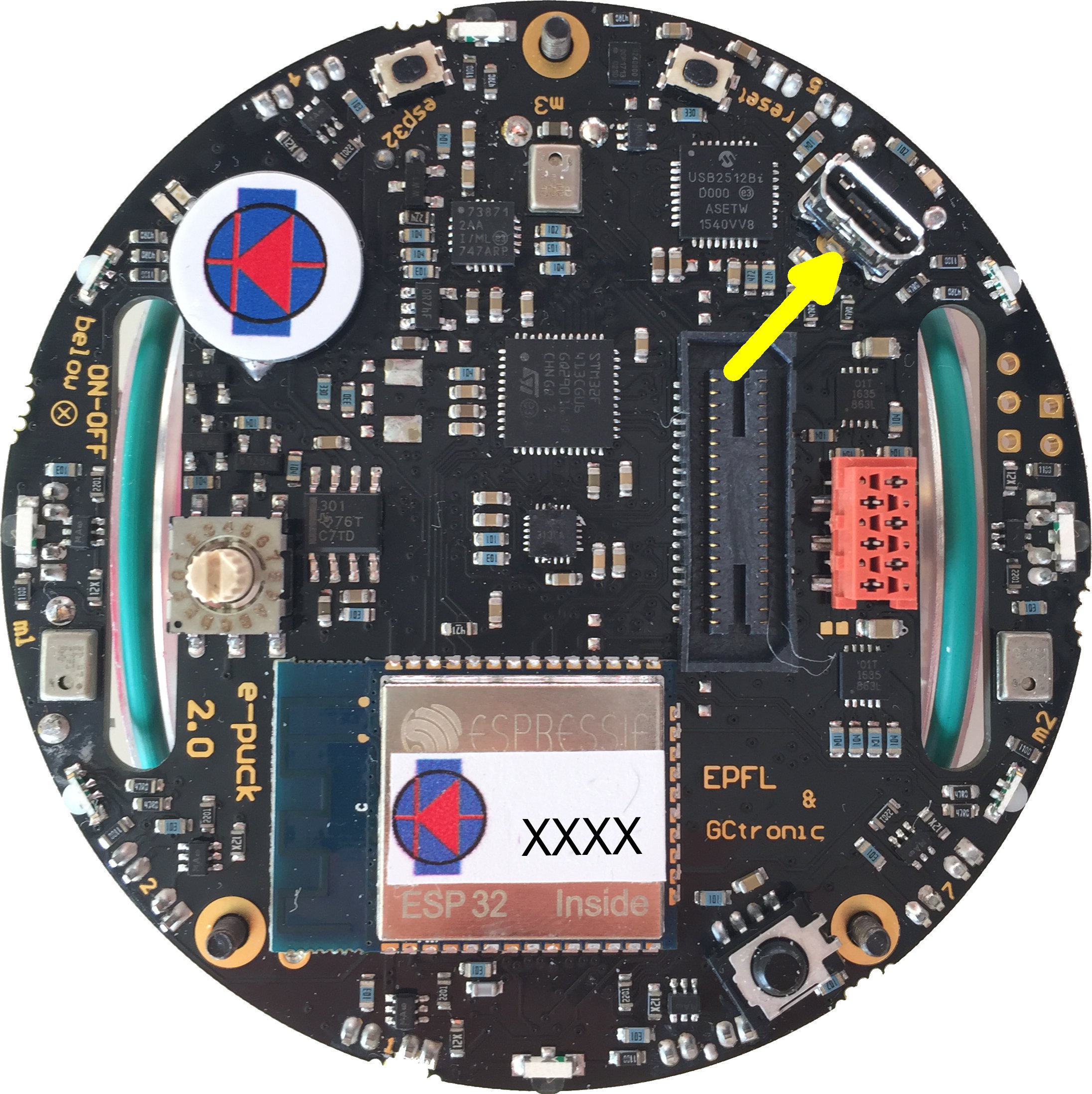
| | A micro USB cable (included with the robot in the package) is needed to connect the robot to the computer. There are two connectors, one placed on top of the robot facing upwards and the other placed on the side of the robot, as shown in the following figures. Both can be used to charge the robot (up to 1 ampere) or to communicate with it, but do not connect two cables at the same time. Connect the USB cable where is more comfortable to you. |
| | ::<span class="plain links">[https://projects.gctronic.com/epuck2/wiki_images/e-puck2-usb-conn.jpg <img width=250 src="https://projects.gctronic.com/epuck2/wiki_images/e-puck2-usb-conn-small.jpg">][https://projects.gctronic.com/epuck2/wiki_images/e-puck2-usb-conn2.jpg <img width=300 src="https://projects.gctronic.com/epuck2/wiki_images/e-puck2-usb-conn2-small.jpg">]</span><br/> |
|
| |
|
| You can download a Webots project containing a demonstration world illustrating the usage of the radio communication between 10 Elisa-3 robots and a supervisor in the following link [https://projects.gctronic.com/elisa3/Elisa-3-webots-radio.zip Elisa-3-webots-radio.zip]. Here is a video of this demo:<br/>
| | ==Installing the USB drivers== |
| {{#ev:youtube|IEgCo3XSESU}}
| | The USB drivers must be installed only for the users of a Windows version older than Windows 10: |
|
| |
|
| ===Onboard behaviors===
| | #Download and open [https://projects.gctronic.com/epuck2/zadig-2.3.exe zadig-2.3.exe] |
| The released firmware contains two basic onboard behaviors: obstacle and cliff avoidance. Both can be enabled and disabled from the computer through the radio (seventh bit of flags byte for obstacle avoidance, eight bit of flags byte for cliff avoidance).
| | #Connect the e-puck2 with the USB cable and turn it on. Three unknown devices appear in the device list of the program, namely '''e-puck2 STM32F407''', '''e-puck2 GDB Server (Interface 0)''' and '''e-puck2 Serial Monitor (Interface 2)'''. |
| The following videos show three robots that have their obstacle avoidance enabled:{{#ev:youtube|EbroxwWG-x4}} {{#ev:youtube|q6IRWRlTQeQ}}
| | #For each of the three devices mentioned above, select the <code>USB Serial (CDC)</code> driver and click on the <code>Install Driver</code> button to install it. Accept the different prompts which may appear during the process. At the end you can simply quit the program and the drivers are installed. These steps are illustrated on Figure 3 below. |
| | ::Note : The drivers installed are located in <code>C:\Users\"your_user_name"\usb_driver</code> |
|
| |
|
| ===Programming===
| | :<span class="plain links">[https://projects.gctronic.com/epuck2/wiki_images/Zadig_e-puck2_STM32F407.png <img width=500 src="https://projects.gctronic.com/epuck2/wiki_images/Zadig_e-puck2_STM32F407.png">]</span><br/> |
| The robot is pre-programmed with a serial bootloader. In order to upload a new program to the robot a micro USB cable is required. The connection with the robot is shown below:<br/>
| | ::''Example of driver installation for e-puck2 STM32F407'' |
| <span class="plainlinks">[http://www.gctronic.com/doc/images/Elisa3.1-programming.jpg <img width=400 src="http://www.gctronic.com/doc/images/Elisa3.1-programming.jpg">]</span> <br/> | |
|
| |
|
| If you are working with the Arduino IDE you don't need to follow this procedure, refer instead to section [http://www.gctronic.com/doc/index.php/Elisa-3#Arduino_IDE_project Arduino IDE project].
| | The drivers are automatically installed with Windows 10, Linux and Mac OS. |
|
| |
|
| <font style="color:red">'''If you encounter some problem during programming (e.g. timeout problems) you can try following this sequence: turn on the robot, unplug the robot from the computer, plug the robot into the computer, it will make some blinks; when the blinks terminate execute the programming command again.<br/>'''</font>
| | Anyway in Linux in order to access the serial ports, a little configuration is needed. Type the following command in a terminal session: <code>sudo adduser $USER dialout</code>. Once done, you need to log off to let the change take effect. |
| <font style="color:red">'''Beware that every time you need to re-program the robot you need to unplug and plug again the cable to the computer.'''</font>
| |
|
| |
|
| ====Windows 7==== | | ==Finding the USB serial ports used== |
| # Download the [https://projects.gctronic.com/elisa3/programming/AVR-Burn-O-Mat-Windows7.zip Windows 7 package] and extract it. The package contains also the FTDI driver.
| | Two ports are created by the e-puck2's programmer when the USB cable is connected to the robot (even if the robot is turned off): |
| # Execute the script <code>config.bat</code> and follow the installation; beware that this need to be done only once. The script will ask you to modify the registry, this is fine (used to save application preferences).
| | * '''e-puck2 GDB Server'''. The port used to program and debug the e-puck2. |
| # Connect the robot to the computer; the COM port will be created.
| | * '''e-puck2 Serial Monitor'''. Serial communication between the PC and the radio module (used also to program the radio module). |
| # Run the application <code>AVR Burn-O-Mat.exe</code>; you need to configure the port to communicate with the robot:
| |
| ## click on <code>Settings => AVRDUDE</code>
| |
| ## in the <code>AVRDUDE Options</code>, on <code>Port</code> enter the name of the port just created when the robot was connected to the computer (e.g. COM10); then click <code>Ok</code>
| |
| # In the <code>Flash</code> section search the hex file you want to upload on the robot.
| |
| # Turn on the robot, wait the blinks terminate and then click on <code>Write</code> in the <code>Flash</code> section.
| |
| # During the programming the robot will blink; at the end you'll receive a message saying <code>Flash succesfully written.</code>
| |
|
| |
|
| ====Mac OS X==== | | A third port could be available depending on the code inside the e-puck2's microcontroller. With the factory firmware a port named '''e-puck2 STM32F407''' is created. |
| The following procedure is tested in Max OS X 10.10, but should work from Mac OS X 10.9 onwards; in these versions there is built-in support for the FTDI devices.
| | ===Windows=== |
| # Download the [https://projects.gctronic.com/elisa3/programming/AVR8-Burn-O-Mat-MacOsX.zip Mac OS X package] and extract it. | | #Open the Device Manager |
| # Execute the script <code>config.sh</code> in the terminal, it will ask you to install the Java Runtime Environment; in case there is a problem executing the script try with <code>chmod +x config.sh</code> and try again. Beware that this need to be done only once. | | #Under '''Ports (COM & LPT)''' you can see the virtual ports connected to your computer. |
| # Connect the robot to the computer; the serial device will be created (something like <code>/dev/tty.usbserial-AJ03296J</code>).
| | #Do a '''Right-click -> properties''' on the COM port you want to identify. |
| # Run the application <code>AVR Burn-O-Mat</code>; you need to configure the port to communicate with the robot: | | #Go under the '''details''' tab and select '''Bus reported device description''' in the properties list. |
| ## click on <code>Settings => AVRDUDE</code>
| | #The name of the port should be written in the text box below. |
| ## in the <code>AVRDUDE Options</code>, on <code>Port</code> enter the name of the port just created when the robot was connected to the computer; then click <code>Ok</code>
| | #Once you found the desired device, you can simply look at its port number '''(COMX)'''. |
| # In the <code>Flash</code> section search the hex file you want to upload on the robot.
| |
| # Turn on the robot, wait the blinks terminate and then click on <code>Write</code> in the <code>Flash</code> section. | |
| # During the programming the robot will blink; at the end you'll receive a message saying <code>Flash succesfully written.</code> | |
|
| |
|
| ====Linux====
| | ===Linux=== |
| The following procedure was tested in Ubunut 12.04, but a similar procedure can be followed in newer systems and other Linux versions.<br/>
| | :1. Open a terminal window (<code>ctrl+alt+t</code>) and enter the following command: <code>ls /dev/ttyACM*</code> |
| You can find a nice GUI for <code>avrdude</code> in the following link [http://burn-o-mat.net/avr8_burn_o_mat_avrdude_gui_en.php http://burn-o-mat.net/avr8_burn_o_mat_avrdude_gui_en.php]; you can download directly the application for Ubuntu from the following link [https://projects.gctronic.com/elisa3/programming/avr8-burn-o-mat-2.1.2-all.deb avr8-burn-o-mat-2.1.2-all.deb].<br/>
| | :2. Look for '''ttyACM0''' and '''ttyACM1''' in the generated list, which are respectively '''e-puck2 GDB Server''' and '''e-puck2 Serial Monitor'''. '''ttyACM2''' will be also available with the factory firmware, that is related to '''e-puck2 STM32F407''' port |
| Double click the package and install it; the executable will be <code>avr8-burn-o-mat</code>.<br/>
| | Note : Virtual serial port numbering on Linux depends on the connections order, thus it can be different if another device using virtual serial ports is already connected to your computer before connecting the robot, but the sequence remains the same. |
| Beware that the application requires the Java SE Runtime Environment (JRE) that you can download from the official page [http://www.oracle.com/technetwork/java/javase/downloads/index.html http://www.oracle.com/technetwork/java/javase/downloads/index.html], alternatively you can issue the command <code>sudo apt-get install openjdk-8-jre</code> in the terminal.
| |
|
| |
|
| The application need a bit of configuration, follow these steps:
| | ===Mac=== |
| :1. connect the robot to the computer, the serial device will be created (something like /dev/USB0) | | :1. Open a terminal window and enter the following command: <code>ls /dev/cu.usbmodem*</code> |
| :2. to use the USB port the permissions need to be set to read and write issueing the command <code>sudo chmod a+rw /dev/ttyUSB0</code>
| | :2. Look for two '''cu.usbmodemXXXX''', where XXXX is the number attributed by your computer. You should find two names, with a numbering near to each other, which are respectively '''e-puck2 GDB Server''' (lower number) and '''e-puck2 Serial Monitor''' (higher number). A third device '''cu.usbmodemXXXX''' will be available with the factory firmware, that is related to '''e-puck2 STM32F407''' port |
| :3. start the application and click on <code>Settings => AVRDUDE</code>
| |
| :4. set the location of <code>avrdude</code> and the related configuration file (refer to the previous section when <code>avrdude</code> was installed to know the exact location); the configuration file is in <code>/etc/avrdude.conf</code> | |
| :3. click <code>OK</code>, close the application and open it again (this is needed to load the configuration file information); click on <code>Settings => AVRDUDE</code>
| |
| :4. select <code>stk500v2</code> as the <code>Programmer</code>
| |
| :5. set the serial port connected to the robot (<code>/dev/ttyUSB0</code>)
| |
| :6. in <code>additional options</code> insert <code>-b 57600</code>, you will end up with a window like the following one:
| |
| <span class="plainlinks">[http://www.gctronic.com/doc/images/avrdude-gui.png <img width=400 src="http://www.gctronic.com/doc/images/avrdude-gui-small.png">]</span>
| |
| :7. click <code>OK</code>; select <code>ATmega2560</code> in the <code>AVR type</code>
| |
| :8. in the <code>Flash</code> section search the hex file you want to upload on the robot; select <code>Intel Hex</code> on the right
| |
| :9. connect the robot to the computer, turn on the robot, wait the blinks terminate and then click on <code>Write</code> in the <code>Flash</code> section
| |
| :10. during the programming the robot will blink; at the end you'll receive a message saying <code>Flash succesfully written.</code>
| |
|
| |
|
| ====Command line====
| | Note : Virtual serial port numbering on Mac depends on the physical USB port used and the device. If you want to keep the same names, you must connect to the same USB port each time. |
| The [http://www.ladyada.net/learn/avr/setup-win.html avrdude] utility is used to do the upload, you can download it directly from the following links depending on your system:
| |
| * [https://projects.gctronic.com/elisa3/programming/WinAVR-20100110-install.exe Windows (tested on Windows 7 and 10)]; <code>avrdude</code> will be installed in the path <code>C:\WinAVR-20100110\bin\avrdude</code>; avrdude version 5.10
| |
| * [https://projects.gctronic.com/elisa3/programming/CrossPack-AVR-20131216.dmg Mac OS X]; <code>avrdude</code> will be installed in the path <code>/usr/local/CrossPack-AVR/bin/avrdude</code>; to check the path issue the commmand <code>which avrdude</code> in the terminal; avrdude version 6.0.1
| |
| * Ubuntu (12.04 32-bit): issue the command <code>sudo apt-get install avrdude</code> in the terminal; <code>avrdude</code> will be installed in the path <code>/usr/bin/avrdude</code>; to check the path issue the commmand <code>which avrdude</code> in the terminal; avrdude version 5.11.1
| |
|
| |
|
| Open a terminal and issue the command <code>avrdude -p m2560 -P COM10 -b 57600 -c stk500v2 -D -Uflash:w:Elisa3-avr-studio.hex:i -v</code><br/>
| | ==PC interface== |
| where <code>COM10</code> must be replaced with your com port and <code>Elisa3-avr-studio.hex</code> must be replaced with your application name; in Mac OS X the port will be something like <code>/dev/tty.usbserial-...</code>, in Ubuntu will be <code>/dev/ttyUSB0</code>.<br/>
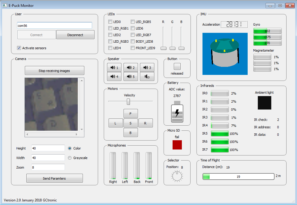
| | <span class="plainlinks">[https://projects.gctronic.com/epuck2/wiki_images/monitor.png <img width=250 src="https://projects.gctronic.com/epuck2/wiki_images/monitor_small.png">]<br/> |
| The [http://www.gctronic.com/doc/index.php/Elisa-3#Basic_demo Basic demo] and [http://www.gctronic.com/doc/index.php/Elisa-3#Advanced_demo Advanced demo] have this command contained in the file <code>program.bat</code> in the <code>default</code> directory within the project, this can be useful for Windows users.<br/>
| | A PC application was developed to start playing with the robot attached to the computer via USB cable: you can have information about all the sensors, receive camera images and control the leds and motors.<br/> |
| | Beware that it's not mandatory to download this application in order to work with the robot, but it is a nice demo that gives you an overview of all the sensors and actuators available on the robot, this is a first step to gain confidence with the robot.<br/> |
|
| |
|
| ===Internal EEPROM===
| | With the factory firmwares programmed in the robot, place the selector in position 8, attach the USB cable and turn on the robot. Enter the correct port (the one related to <code>e-puck2 STM32F407</code>) in the interface and click <code>connect</code>. |
| The internal 4 KB EEPROM that resides in the microcontroller is pre-programmed with the robot ID in the last two bytes (e.g. if ID=3200 (0x0C80), then address 4094=0x80 and address 4095=0x0C). The ID represents also the RF address that the robot uses to communicate with the computer and is automatically read at startup (have a look a the firmware for more details).<br/>
| |
| Moreover the address 4093 is used to save the clock calibration value that is found during production/testing of the robots; this value hasn't to be modified otherwise some functionalities such as tv remote control could not work anymore. For more information on clock calibration refers to the applicaiton note [https://projects.gctronic.com/elisa3/AVR053-Calibration-RC-oscillator.pdf AVR053: Calibration of the internal RC oscillator].<br/>
| |
| The Elisa-3 robot supports an autonomous calibration process and the result of this calibration is saved in EEPROM starting at address 3946 to 4092.<br/>
| |
| <font style="color:red">'''The size of usable EEPROM is thus 3946 bytes (0-3945) and the remaining memory must not be modified/erased.'''</font> | |
|
| |
|
| In order to program the eeprom an AVR programmer is required, we utilize the Pocket AVR Programmer from Sparkfun (recognized as USBtiny device); then with the [http://www.ladyada.net/learn/avr/setup-win.html avrdude] utility the following command has to be issued:
| | The source code is available from the repository [https://github.com/e-puck2/monitor https://github.com/e-puck2/monitor].<br/> |
| <pre>
| |
| avrdude -p m2560 -c usbtiny -v -U eeprom:w:Elisa3-eeprom.hex:i -v -B 1
| |
| </pre>
| |
| where ''Elisa3-eeprom.hex'' is the EEPROM memory saved as Intel Hex format ([https://projects.gctronic.com/elisa3/Elisa3-eeprom.hex eeprom example]); a possible tool to read and write Intel Hex format is [https://projects.gctronic.com/elisa3/G32setup_12004-intel-hex-editor.exe Galep32 from Conitec Datensysteme].<br/>
| |
| Alternatively a program designed to writing to these EEPROM locations can be uploaded to the robot, in case an AVR programmer isn't available. The project source is available in the repository [https://github.com/gctronic/elisa3_eeprom.git https://github.com/gctronic/elisa3_eeprom.git]; it is simply needed to modify the address, rebuild and upload to the robot.
| |
|
| |
|
| ===Bootloader=== | | ===Available executables=== |
| In case the bootloader of the Elisa-3 is erased by mistake, then you can restore it by using an AVR programmer. You can download the bootloader from here [https://projects.gctronic.com/elisa3/stk500v2_20.03.18_13b46ce.hex stk500v2.hex]; the source code is available from the repository [https://github.com/gctronic/elisa3_bootloader.git https://github.com/gctronic/elisa3_bootloader.git].<br/>
| | * [https://projects.gctronic.com/epuck2/monitor_win.zip Windows executable]: tested on Windows 7 and Windows 10 |
| <code>Avrdude</code> can be used to actually write the bootloader to the robot with a command similar to the following one:<br/>
| | * [https://projects.gctronic.com/epuck2/monitor_mac.zip Max OS X executable] |
| <code>avrdude -p m2560 -c stk500v2 -P COM348 -v -U lfuse:w:0xE2:m -U hfuse:w:0xD8:m -U efuse:w:0xFF:m -V -U flash:w:stk500v2.hex:i -v -B 2</code><br/>
| | * [https://projects.gctronic.com/epuck2/monitor_linux64bit.tar.gz Ubuntu 14.04 (or later) - 64 bit] |
| Here we used a programmer recognized as a serial device (port COM348) that utilizes the <code>stk500v2</code> protocol.
| | On Linux remember to apply the configuration explained in the chapter [http://www.gctronic.com/doc/index.php?title=e-puck2#Installing_the_USB_drivers Installing the USB drivers] in order to access the serial port. |
|
| |
|
| ==Base-station== | | ==Installing the dependencies for firmwares updates== |
| This chapter explains informations that aren't needed for most of the users since the radio module is ready to be used and don't need to be reprogrammed. Only if you are interested in the firmware running in the radio module and on how to reprogram it then refer to section [http://www.gctronic.com/doc/index.php/Elisa#Base-station http://www.gctronic.com/doc/index.php/Elisa#Base-station] (chapter 4.2) of the Elisa robot wiki.
| | You can update the firmware for all 3 chips: the main microcontroller, the radio module and the programmer. For doing that, you need some tools to be installed on the system. |
|
| |
|
| ==PC side== | | ===Windows=== |
| This section gives informations related to the radio module connected to the computer; if you don't have a radio module you can skip this section.
| | To upload a new firmware in the microcontroller or in the radio module, you don't need to install anything, the packages provided include all the dependencies. |
| ===Elisa-3 library===
| |
| This library simplify the implementation of applications on the pc side (where the radio base-station is connected) that will take control of the robots and receive data from them. Some basic examples will be provided in the following sections to show how to use this library.<br/>
| |
| The source code of the library is available in the repository [https://github.com/gctronic/elisa3_remote_library https://github.com/gctronic/elisa3_remote_library].
| |
|
| |
|
| ===Multiplatform monitor===
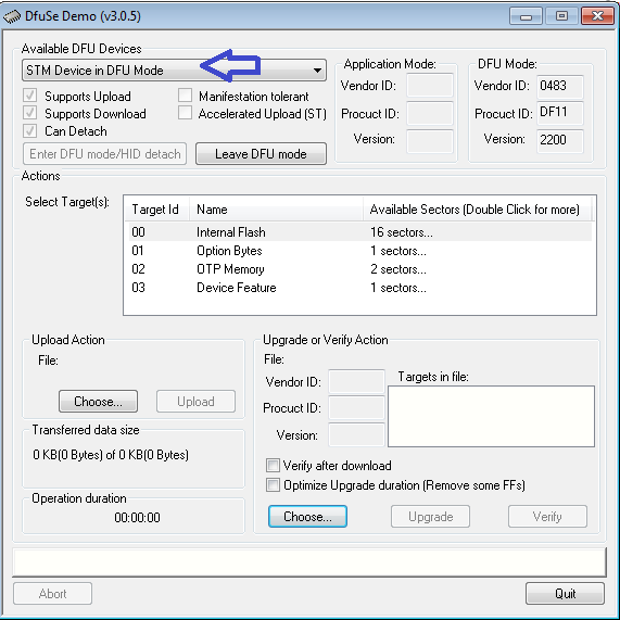
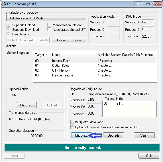
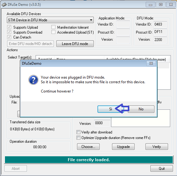
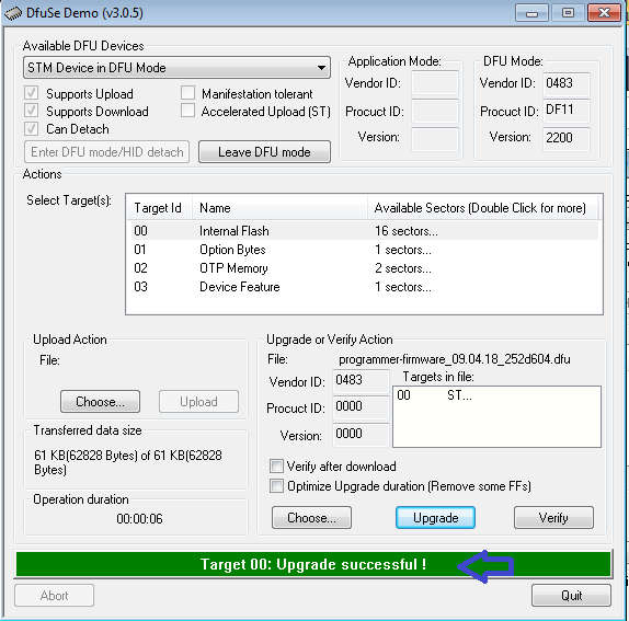
| | To upload a new firmware in the programmer you need to install an application called <code>DfuSe</code> released by STMicroelectronics. You can download it from [https://projects.gctronic.com/epuck2/en.stsw-stm32080_DfuSe_Demo_V3.0.5.zip DfuSe_V3.0.5.zip]. |
| The demo is a command line monitor that shows all the sensors information (e.g. proximity, ground, acceleromter, battery, ...) and let the user move the robot and change its colors and behavior with the keyboard. The data are sent using the protocol described in the previous section. <br/>
| |
| The following figures show the monitor on the left and the available commands on the right. <br/>
| |
| <span class="plainlinks">[http://www.gctronic.com/doc/images/Cmd-line-monitor.jpg <img width=400 src="http://www.gctronic.com/doc/images/Cmd-line-monitor.jpg">]</span>
| |
| <span class="plainlinks">[http://www.gctronic.com/doc/images/Pc-side-commands2.jpg <img width=400 src="http://www.gctronic.com/doc/images/Pc-side-commands2.jpg">]</span>
| |
| <br/>
| |
|
| |
|
| The source can be downloaded from the repository [https://github.com/gctronic/elisa3_remote_monitor https://github.com/gctronic/elisa3_remote_monitor]. <br/>
| | ===Linux=== |
| | To upload a new firmware in the microcontroller or in the radio module, you need: |
| | * Python (>= 3.4): <code>sudo apt-get install python3</code> |
| | * Python pip: <code>sudo apt-get install -y python3-pip</code> |
| | * pySerial (>= 2.5): <code>sudo pip3 install pyserial</code> |
|
| |
|
| ====Windows====
| | To upload a new firmware in the programmer you need: |
| Execution:
| | * dfu-util: <code>sudo apt-get install dfu-util</code> |
| * install the driver contained in the [http://www.nordicsemi.com/eng/Products/2.4GHz-RF/nRFgo-Studio nRFgo Studio tool] if not already done; this let the base-station be recognized as a WinUSB device (bootloader), independently of whether the libusb library is installed or not
| |
| * once the driver is installed, the pre-compiled "exe" (under <code>\bin\Release</code> dir) should run without problems; the program will prompt you the address of the robot you want to control | |
|
| |
|
| Compilation:<br/>
| | ===Mac=== |
| the Code::Blocks project should already be setup to reference the Elisa-3 library headers and lib files, anyway you need to put this project within the same directory of the Elisa-3 library, e.g. you should have a tree similar to the following one:
| | Install the [https://brew.sh Homewbrew] package manager by opening a terminal and issueing:<br/> |
| * Elisa-3 demo (parent dir)
| | <code>/usr/bin/ruby -e "$(curl -fsSL https://raw.githubusercontent.com/Homebrew/install/master/install)"</code><br/> |
| ** <code>elisa3_remote_library</code> (Elisa-3 library project)
| | and then:<br/> |
| ** <code>elisa3_remote_monitor</code> (current project)
| | <code>brew upgrade</code><br/> |
|
| |
|
| ====Linux / Mac OS X====
| | To upload a new firmware in the microcontroller or in the radio module, you need: |
| The project was tested to work also in Ubuntu and Mac OS X (no driver required). <br/>
| | * Python (>= 3.4): <code>brew install python</code> (it will install also <code>pip</code>) |
| Compilation:
| | * pySerial (>= 2.5): <code>pip3 install pyserial</code> |
| * you need to put this project within the same directory of the Elisa-3 library
| |
| * build command: go under "linux" dir and type <code>make clean && make</code>
| |
| Execution:
| |
| * <code>sudo ./main</code>
| |
|
| |
|
| ===Communicate with 4 robots simultaneously===
| | To upload a new firmware in the programmer you need: |
| This example shows how to interact with 4 robots simlutaneously, basically it shows the sensors information (proximity and ground) coming from 4 robots and let control one robot at a time through the keyboard (you can change the robot you want to control). The source can be downloaded from the repository [https://github.com/gctronic/elisa3_remote_multiple https://github.com/gctronic/elisa3_remote_multiple]. For building refer to the section [http://www.gctronic.com/doc/index.php/Elisa-3#Multiplatform_monitor Multiplatform monitor].
| | * dfu-util: <code>brew install dfu-util</code> |
|
| |
|
| ===Obstacle avoidance=== | | ==PC side development== |
| This demo implements the ''obstacle avoidance'' behavior controlling the robot from the pc through the radio; this means that the robot reacts only to the commands received using the basic communication protocol and has no "intelligence" onboard. The demo uses the information gathered from the 3 front proximity sensors and set the motors speed accordingly; moreover the RGB LED is updated with a random color at fixed intervals. <br/> | | This section is dedicated to the users that develop algorithms on the PC side and interact with the robot remotely through a predefined communication protocol. These users don't modify the firmware of the robot, but instead they use the factory firmware released with the robot. They update the robot firmware only when there is an official update. <br/> |
| The source can be downloaded from the repository [https://github.com/gctronic/elisa3_remote_oa https://github.com/gctronic/elisa3_remote_oa]. For building refer to the section [http://www.gctronic.com/doc/index.php/Elisa-3#Multiplatform_monitor Multiplatform monitor]. <br/> | | The remote control of the robot, by receiving sensors values and setting the actuators, is done through the following channels: Bluetooth, Bluetooth Low Energy, WiFi, USB cable.<br/> |
| The following video shows the result: <br/>
| | Examples of tools/environment used by these users: |
| {{#ev:youtube|F_b1TQxZKos}}
| | # Aseba |
| | # Simulator (e.g. Webots) |
| | # ROS |
| | # iOS, Android apps |
| | # Custom PC application |
| | # IoT (e.g. IFTTT) |
| | If you fall into this category, then follow this section for more information: [http://www.gctronic.com/doc/index.php?title=e-puck2_PC_side_development PC side development].<br/> |
|
| |
|
| It is available also the same example but with 4 robots controlled simultaneously; the source can be downloaded from the branch <code>4robots</code> of the repository [https://github.com/gctronic/elisa3_remote_oa https://github.com/gctronic/elisa3_remote_oa]<br/>
| | =Main microcontroller= |
| It is easy to extend the previous example in order to control many robots, the code that controls 8 robots simultaneously can be downloaded from the branch <code>8robots</code> of the repository [https://github.com/gctronic/elisa3_remote_oa https://github.com/gctronic/elisa3_remote_oa].
| | The e-puck2 robot main microcontroller is a 32-bit STM32F407 that runs at 168 MHz (210 DMIPS) and include DSP, FPU and DMA capabilities. The version chosen for the e-puck2 has 192 KB of total RAM and 1024 KB of flash, so there is a lot of memory to work with.<br/> |
| | This chip is responsible for handling the sensors and actuators and runs also the demos and algorithms. |
|
| |
|
| ===Cliff avoidance=== | | ==Factory firmware== |
| This demo implements the ''cliff avoidance'' behavior controlling the robot from the pc through the radio; as with the ''obstacle avoidance'' demo, the robot reacts only to the commands received from the radio. The demo uses the information gathered from the 4 ground sensors to stop the robot when a cliff is detected (threshold tuned to run in a white surface); moreover the RGB LED is updated with a random color at fixed intervals. <br/>
| | The main microcontroller of the robot is initially programmed with a firmware that includes many demos that could be started based on the selector position, here is a list of the demos with related position and a small description: |
| The source can be downloaded from the repository [https://github.com/gctronic/elisa3_remote_cliff https://github.com/gctronic/elisa3_remote_cliff]. For building refer to the section [http://www.gctronic.com/doc/index.php/Elisa-3#Multiplatform_monitor Multiplatform monitor]. <br/>
| | * Selector position 0: Aseba |
| The following video shows the result: <br/>
| | * Selector position 1: Shell |
| {{#ev:youtube|uHy-9XXAHcs}}
| | * Selector position 2: Read proximity sensors and when an object is near a proximity, turn on the corresponding LED |
| | * Selector position 3: Asercom protocol v2 (BT) |
| | * Selector positoin 4: Range and bearing extension (receiver) |
| | * Selector position 5: Range and bearing extension - clustering demo (simultaneous transmitter and receiver). |
| | * Selector position 6: Move the robot back and forth exploiting the gyro, with LEDs animation |
| | * Selector position 7: Play a wav (mono, 16 KHz) named "example.wav" from the micro sd when pressing the button |
| | * Selector position 8: Asercom protocol v2 (USB) |
| | * Selector position 9: Local communication: transceiver |
| | * Selector position 10: this position is used to work with the Linux extensions. To work with gumstix refer to [http://www.gctronic.com/doc/index.php?title=Overo_Extension#e-puck2 Overo Extension: e-puck2] , to work with Pi-puck refer to [http://www.gctronic.com/doc/index.php?title=Pi-puck#Requirements Pi-puck: Requirements ]. |
| | * Selector position 11: Simple obstacle avoidance + some animation |
| | * Selector position 12: Hardware test |
| | * Selector position 13: LEDs reflect orientation of the robot |
| | * Selector position 14: Compass |
| | * Selector position 15: WiFi mode |
| | The pre-built firmware is available here [https://projects.gctronic.com/epuck2/e-puck2_main-processor_10.12.21_52ffc6b.elf main microcontroller factory firmware (10.12.21)]. |
|
| |
|
| ===Set robots state from file=== | | ==Firmware update== |
| This project show how to send data to robots for which we will know the address only at runtime, in particular the content of the packets to be transmitted is parsed from a csv file and the interpreted commands are sent to the robots one time. The source can be downloaded from the repository [https://github.com/gctronic/elisa3_remote_file https://github.com/gctronic/elisa3_remote_file]. For building refer to the section [http://www.gctronic.com/doc/index.php/Elisa-3#Multiplatform_monitor Multiplatform monitor]. <br/>
| | Now and then there could be an official firmware update for the robot and it's important to keep the robot updated with the last firmware to get possibile new features, improvements and for bug fixes.<br/> |
| | The onboard programmer run a GDB server, so we use GDB commands to upload a new firmware, for this reason a toolchain is needed to upload a new firmware to the robot.<br/> |
| | The following steps explain how to update the main microcontroller firmware:<br/> |
| | 1. Download the package containing the required toolchain and script to program the robot: [https://projects.gctronic.com/epuck2/e-puck2-prog-main-micro-windows.zip Windows], Linux [https://projects.gctronic.com/epuck2/e-puck2-prog-main-linux32.tar.gz 32 bits]/[https://projects.gctronic.com/epuck2/e-puck2-prog-main-linux64.tar.gz 64 bits], [https://projects.gctronic.com/epuck2/e-puck2-prog-main-micro-macos.zip Mac OS]<br/> |
| | 2. Download the last version of the [https://projects.gctronic.com/epuck2/e-puck2_main-processor_10.12.21_52ffc6b.elf main microcontroller factory firmware (10.12.21)], or use your custom firmware<br/> |
| | 3. Extract the package and put the firmware file (with <code>elf</code> extension) inside the package directory; beware that only one <code>elf</code> file must be present inside this directory<br/> |
| | 4. Attach the USB cable and turn on the robot<br/> |
| | 5. Run the script from the package directory:<br/> |
| | :Windows: double click <code>program.bat</code><br/> |
| | :Linux/Mac: issue the following command in a terminal <code>./program.sh</code>. If you get permission errors, then issue <code>sudo chmod +x program.sh</code> to let the script be executable.<br/> |
|
| |
|
| =Odometry=
| | When the upload is complete you'll see an output like in the following figure:<br/> |
| The odometry of Elisa-3 is quite good even if the speed is only measured by back-emf. On vertical surfaces the absolute angle is given by the accelerometer measuring g... quite a fix reference without drifting ;-)<br/>
| | <span class="plain links">[https://projects.gctronic.com/epuck2/wiki_images/f407-flashing.png <img width=400 src="https://projects.gctronic.com/epuck2/wiki_images/f407-flashing.png">]</span><br/> |
| A fine calibration of the right and left wheel speed parameters might give better results.
| | The final lines should contain the entry <code>".data",</code>, this means that the upload was successfull. You can then close the terminal window if it is still open. |
| However the current odometry is a good estimate of the absolute position from a starting point.
| |
| The experiments are performed on a square labyrinth and the robot advances doing obstacle avoidance. The on-board calculated (x,y,theta) position is sent to a PC via radio and logged for further display.<br/>
| |
| <span class="plainlinks">[http://www.gctronic.com/img2/odometry-vertical.jpg <img width=400 src="http://www.gctronic.com/img2/odometry-vertical-small2.jpg">]</span> <br/> | |
| Details about the code can be found in the [http://www.gctronic.com/doc/index.php/Elisa-3#Advanced_demo advanced-demo] project, in particular the ''motors.c'' source file. The PC application used for logging data is the [http://www.gctronic.com/doc/index.php/Elisa-3#Multiplatform_monitor_.28pc_side.29 monitor].
| |
| ==Autonomous calibration==
| |
| Since the motors can be slightly different a calibration can improve the behavior of the robot in terms of maneuverability and odometry accuracy.
| |
| An autonomous calibration process is implemented onboard: basically a calibration is performed for both the right and left wheels in two modes that are forward and backward with speed control enabled. In order to let the robot calibrate istelf a white sheet in which a black line is drawed is needed; the robot will measure the time between detection of the line at various speeds. The calibration sheet can be downloaded from the following link [https://projects.gctronic.com/elisa3/calibration-sheet.pdf calibration-sheet.pdf]. <br/>
| |
| In order to accomplish the calibration the robot need to be programmed with the [http://www.gctronic.com/doc/index.php/Elisa-3#Advanced_demo advanced firmare] and a specific command has to be sent to the robot through the radio module or the TV remote; if you are using the radio module you can use the [http://www.gctronic.com/doc/index.php/Elisa-3#Multiplatform_monitor_.28pc_side.29 monitor application] in which the letter ''l (el)'' is reserved to launch the calibration, otherwise if you have a TV remote control you can press the button ''5''.
| |
| The sequence is the following:<br/>
| |
| 1. put the selector in position 8<br/>
| |
| 2. place the robot near the black line as shown below; the left motor is the first to be calibrated. Pay attention to place the right wheel as precise as possible with the black line<br/>
| |
| [http://www.gctronic.com/doc/images/elisa3-calibration-1.jpg <img width=300 src="http://www.gctronic.com/doc/images/elisa3-calibration-1_small.jpg">]
| |
| [http://www.gctronic.com/doc/images/elisa3-calibration-2.jpg <img width=300 src="http://www.gctronic.com/doc/images/elisa3-calibration-2_small.jpg">]<br/>
| |
| 3. once the robot is placed you can type the ''l (el)'' command (or press the button ''5''); wait a couple of minutes during which the robot will do various turns at various speed in the forward direction and then in the backward direction<br/>
| |
| 4. when the robot terminated (robot is stopped after going backward at high speed) you need to place it in the opposite direction in order to calibrate the right motor, as shown below.<br/>
| |
| [http://www.gctronic.com/doc/images/elisa3-calibration-3.jpg <img width=300 src="http://www.gctronic.com/doc/images/elisa3-calibration-3_small.jpg">]<br/>
| |
| 5. once the robot is placed you can type again the ''l (el)'' command (or press the button ''5'')<br/>
| |
| 6. when the robot finish, the calibration process is also terminated.<br/>
| |
|
| |
|
| The previous figures show a robot without the top diffuser, anyway you don't need to remove it!
| | If you encounter some problem, try to unplug and plug again the USB cable and power cycle the robot, then retry. |
|
| |
|
| =Tracking= | | ==Robot side development== |
| ==Assembly documentation==
| | If you are an embedded developer and are brave enough, then you have complete access to the source code running on the robot, so you can discover what happen inside the main microcontroller and modify it to accomodate your needs. Normally the users that fall into this category develop algorithms optimized to run directly on the microcontroller, such as: |
| You can download the documentation from here [https://projects.gctronic.com/elisa3/tracking-doc.pdf tracking-doc.pdf].<br/>
| | # onboard image processing |
| Have a look also at the video:<br/>
| | # swarm algorithms |
| {{#ev:youtube|92pz28hnteY}}<br/>
| | # fully autonomous behaviors |
| | # ... |
| | For more information about programming the robot itself, refer to section [http://www.gctronic.com/doc/index.php?title=e-puck2_robot_side_development Robot side development] |
|
| |
|
| ==SwisTrack== | | =Radio module= |
| Some experiments are done with the [https://en.wikibooks.org/wiki/SwisTrack SwisTrack software] in order to be able to track the Elisa-3 robots through the back IR emitter, here is a resulting image with 2 robots:<br/>
| | The radio module chosen for the e-puck is the new ESP32 chip from [https://www.espressif.com/ Espressif], integrating a dual core that run up to 240 MHz, 4 MB of flash and 520 KB of RAM. It supports WiFi standards 802.11 b/g/n (access point mode supported), Bluetooth and Bluetooth LE 4.2. It is the successor of the ESP8266 chip. The following figure shows the various peripherals available on the ESP32:<br/> |
| <span class="plainlinks">[http://www.gctronic.com/doc/images/elisa-3-tracking-2robots.jpg <img width=300 src="http://www.gctronic.com/doc/images/elisa-3-tracking-2robots-small.jpg">]</span><br/> | | <span class="plain links"><img width=400 src="https://projects.gctronic.com/epuck2/wiki_images/esp32-peripherals.png"></span> |
| The pre-compiled SwisTrack software (Windows) can be downloaded from the following link [https://projects.gctronic.com/elisa3/SwisTrackEnvironment-10.04.13.zip SwisTrack-compiled]. <!--; it contains also the configuration for the Elisa-3 named ''elisa-3-usb.swistrack''.<br/> -->
| |
| <!--
| |
| We used the ''Trust Spotlight Pro'' webcam, removed the internal IR filter and placed an external filter that let trough the red-IR wavelength. This filter configuration eases the tracking of the robots. The camera parameters (brightness=-64, contrast=0, saturation=100, gamma=72, gain=0) where tuned to get the best possible results, if another camera would be used a similar tuning has to be done again.
| |
| -->
| |
|
| |
|
| The following video shows the tracking of 5 robots:<br/>
| | This chip first of all is responsible for handling the wireless communication, moreover it handles also the RGB LEDs (with PWM) and the user button. The RGB LEDs and button are connected to the radio module due to the pin number limitation on the main microcontroller. |
| {{#ev:youtube|33lrIUux_0Q}}<br/>
| |
| The SwisTrack software lets you easily log also the resulting data that you can then elaborate, here is an example taken from the experiment using 5 robots:<br/>
| |
| <span class="plainlinks">[http://www.gctronic.com/doc/images/swistrack-output.jpg <img width=300 src="http://www.gctronic.com/doc/images/swistrack-output-small.jpg">]</span><br/>
| |
|
| |
|
| The following video shows the test done with 20, 30 and 38 Elisa-3 robots, the tracking is still good; it's important to notice that we stopped to 38 Elisa-3 robots because are the ones we have in our lab.<br/> | | ==Factory firmware== |
| {{#ev:youtube|5LAccIJ9Prs}}<br/>
| | The radio module of the robot is initially programmed with a firmware that supports Bluetooth communication.<br/> |
| | The pre-built firmware is available here [https://projects.gctronic.com/epuck2/esp32-firmware_11.12.18.zip radio module factory firmware (11.12.18)]. |
|
| |
|
| ==Position control== | | ==WiFi firmware== |
| We developed a simple position control example that interacts with Swistrack through a TCP connection and control 4 robots simultaneously; the orientation of the robots is estimated only with the Swistrack information (delta position), future improvements will integrate odometry information. The following video shows the control of 4 robots that are driven in a ''8-shape''.<br/>
| | At the moment the factory firmware supports only Bluetooth, if you want to work with WiFi you need to program the radio with a dedicated firmware, refer to section [http://www.gctronic.com/doc/index.php?title=e-puck2_PC_side_development#WiFi PC side development: WiFi]. |
| {{#ev:youtube|ACaGNEQHayc}}<br/>
| |
| <span class="plainlinks">[http://www.gctronic.com/doc/images/tracking-8shape.jpg <img width=300 src="http://www.gctronic.com/doc/images/tracking-8shape-small.jpg">]</span><br/>
| |
| All the following projects require the [http://www.gctronic.com/doc/index.php/Elisa-3#Elisa-3_library Elisa-3 library], for building refer to the section [http://www.gctronic.com/doc/index.php/Elisa-3#Multiplatform_monitor Multiplatform monitor].
| |
|
| |
|
| * Horizontal position control (4 robots): the source code can be downloaded from [https://projects.gctronic.com/elisa3/position-control-pattern-horizontal-4-robots-rev245-15.01.21.zip position-control-pattern-horizontal-4-robots.zip] (Code::Blocks project).<br/>
| | ==BLE firmware== |
| One of the characteristics of the Elisa-3 robot is that it can move in vertical thanks to its magnetic wheels, thus we developed also a vertical position control that use accelerometer data coming from the robot to get the orientation of the robot (more precise) instead of estimating it with the Swistrack information, you can download the source code from the following link:
| | At the moment the factory firmware supports only calssic Bluetooth, if you want to work with Bluetooth Low Energy you need to program the radio with a dedicated firmware, refer to section [http://www.gctronic.com/doc/index.php?title=e-puck2_mobile_phone_development Mobile phone development]. |
| * Vertical position control (4 robots): [https://projects.gctronic.com/elisa3/position-control-pattern-vertical-4-robots-rev245-15.01.21.zip position-control-pattern-vertical-4-robots.zip] (Code::Blocks project).<br/>
| |
| We developed also an example of position control that control a single robot (code adapted from previous example) that can be useful during the initial environment installation/testing; you can download the source code from the following link:
| |
| * Horizontal position control (1 robot): [https://projects.gctronic.com/elisa3/position-control-pattern-horizontal-1-robot-rev245-15.01.21.zip position-control-pattern-horizontal-1-robot.zip] (Code::Blocks project).<br/>
| |
| Another good example to start playing with the tracking is an application that lets you specify interactively the target point that the robot should reach; you can download the source code of this application from the following link:
| |
| * Go to target point: [https://projects.gctronic.com/elisa3/position-control-goto-pos-horizontal-1-robot-rev245-15.01.21.zip position-control-goto-pos-horizontal-1-robot.zip] (Code::Blocks project).<br/>
| |
|
| |
|
| ==Utilities== | | ==Firmware update== |
| In order to adjust the IR camera position it is useful to have an application that turn on the back IR of the robots. The following application [https://projects.gctronic.com/elisa3/back-IR-on-4-robots-rev245-15.01.21.zip back-IR-on-4-robots-rev245-15.01.21.zip] is an example that turn on the back IR of 4 robots, their addresses are asked to the user at the execution. | | In order to update the firmware of the ESP32 WiFi module you need to use a python script called <code>esptool</code> provided by [https://www.espressif.com/ Espressif] (manufacturer of the chip). This script was modified to work with the e-puck2 robot and is included in the provided package. The following steps explain how to update the radio module firmware:<br/> |
| | 1. Download the package containing the required tools and script to program the robot: [https://projects.gctronic.com/epuck2/e-puck2-prog-radio-windows.zip Windows], [https://projects.gctronic.com/epuck2/e-puck2-prog-radio-macos.zip Linux / Mac]<br/> |
| | 2. Download the last version of the [https://projects.gctronic.com/epuck2/esp32-firmware_11.12.18.zip radio module factory firmware (11.12.18)], or use another firmware (e.g. WiFi, BLE, your own). The firmware is composed by 3 files named <code>bootloader.bin</code>, <code>ESP32_E-Puck_2.bin</code> and <code>partitions_singleapp.bin</code><br/> |
| | 3. Extract the package and put the firmware files inside the package directory; beware that the name of the <code>.bin</code> files must be the same as indicated in step 2<br/> |
| | 4. Attach the USB cable and turn on the robot<br/> |
| | 5. Run the script from the package directory:<br/> |
| | :Windows: double click <code>program.bat</code><br/> |
| | :Linux/Mac: issue the following command in a terminal <code>./program.sh</code>. If you get permission errors, then issue <code>sudo chmod +x program.sh</code> to let the script be executable.<br/> |
|
| |
|
| =Local communication=
| | The upload should last about 10-15 seconds and you'll see the progress as shown in the following figure:<br/> |
| {{#ev:youtube|7bxIR0Z3q3M}}<br/>
| | <span class="plain links">[https://projects.gctronic.com/epuck2/wiki_images/esp32-flashing1.png <img width=400 src="https://projects.gctronic.com/epuck2/wiki_images/esp32-flashing1.png">]</span><br/> |
| The [http://www.gctronic.com/doc/index.php/Elisa-3#Advanced_demo advanced firmware] is needed in order to use the local communication. You can find some examples on how to use this module in the main, refers to demos in selector position from 11 to 14. <br/>
| | When the upload is complete you'll see that all 3 bin files are uploaded correctly as shown in the following figure:<br/> |
| Here are some details about the current implementation of the communication module:
| | <span class="plain links">[https://projects.gctronic.com/epuck2/wiki_images/esp32-flashing2.png <img width=400 src="https://projects.gctronic.com/epuck2/wiki_images/esp32-flashing2.png">]</span><br/> |
| * use the infrared sensors to exchange data, thus during reception/transmission the proximity sensors cannot be used to avoid obstacles; in the worst case (continuous receive and transmit) the sensor update frequency is about 3 Hz
| |
| * bidirectional communication
| |
| * id and angle of the proximity sensor that received the data are available
| |
| * the throughput is about 1 bytes/sec
| |
| * maximum communication distance is about 5 cm
| |
| * no reception/transmission queue (only one byte at a time)
| |
| * the data are sent using all the sensors, cannot select a single sensor from which to send the data. The data isn't sent contemporaneously from all the sensors, but the sensors used are divided in two groups of 4 alternating sensors (to reduce consumption)
| |
|
| |
|
| =ROS=
| | Sometime you could encounter a timeout error as shown in the following figures; in these cases you need to unplug and plug again the USB cable and power cycle the robot, then you can retry.<br/> |
| This chapter explains how to use ROS with the elisa-3 robots; the radio module is needed here. Basically all the sensors are exposed to ROS and you can also send commands back to the robot through ROS. The ROS node is implemented in cpp. Here is a general schema:<br/>
| | <span class="plain links">[https://projects.gctronic.com/epuck2/wiki_images/esp32-flashing3.png <img width=400 src="https://projects.gctronic.com/epuck2/wiki_images/esp32-flashing3.png">]</span> |
| <span class="plainlinks">[http://www.gctronic.com/doc/images/elisa-ros-schema.png <img width=450 src="http://www.gctronic.com/doc/images/elisa-ros-schema-small.png">]</span> | | <span class="plain links">[https://projects.gctronic.com/epuck2/wiki_images/esp32-flashing4.png <img width=400 src="https://projects.gctronic.com/epuck2/wiki_images/esp32-flashing4.png">]</span><br/> |
| ''<font size="2">Click to enlarge</font>''<br/>
| |
|
| |
|
| First of all you need to install and configure ROS, refer to [http://wiki.ros.org/Distributions http://wiki.ros.org/Distributions] for more informations. Alternatively you can download directly a virtual machine pre-installed with everything you need, refer to section [http://www.gctronic.com/doc/index.php/Elisa-3#Virtual_machine virtual machine]; this is the preferred way.
| | ==Development== |
| :*<font style="color:red"> This tutorial is based on ROS Hydro</font>. The same instructions are working with ROS Noetic, beware to use <code>noetic</code> instead of <code>hydro</code> when installing the packages.
| | Probably, you'll never need to touch the firmware running in the radio module, but in case you need to modify the code or you're simply curious about what is happening at the low level, then refer to the section [http://www.gctronic.com/doc/index.php?title=e-puck2_radio_module_development Radio module development]. |
| :* If you downloaded the pre-installed VM you can go directly to section [http://www.gctronic.com/doc/index.php/Elisa-3#Running_the_ROS_node Running the ROS node].
| |
|
| |
|
| The ROS elisa-3 node based on roscpp can be found in the following repository [https://github.com/gctronic/elisa3_node_cpp https://github.com/gctronic/elisa3_node_cpp].<br/> | | =Programmer= |
| | The e-puck2 robot is equipped with an onboard programmer and debugger that let you update the firmware of the robot and debug your code easily using a standard USB interface. There is a dedicated STM32F413 microcontroller that acts as the programmer with built in GDB server, so you can control exactly what happens using the [https://www.gnu.org/software/gdb/ GNU Project Debugger] in your host machine.<br/> |
| | The programmer microcontroller is also in charge of handling various low level features such as the configuration of the USB hub and the power button. |
|
| |
|
| ==Initial configuration== | | ==Factory firmware== |
| The following steps need to be done only once after installing ROS: | | The programmer is initially programmed with a firmware based on a '''''modified version''''' of [https://github.com/blacksphere/blackmagic/wiki Black Magic Probe programmer/debugger].<br/> |
| :1. If not already done, create a catkin workspace, refer to [http://wiki.ros.org/catkin/Tutorials/create_a_workspace http://wiki.ros.org/catkin/Tutorials/create_a_workspace]. Basically you need to issue the following commands:
| | The pre-built firmware is available here [https://projects.gctronic.com/epuck2/e-puck2_programmer_28.05.20_3b600ec.bin programmer-firmware.bin (28.05.20)]; it is also available in dfu format here [https://projects.gctronic.com/epuck2/e-puck2_programmer_28.05.20_3b600ec.dfu programmer-firmware.dfu (28.05.20)]. |
| <pre> mkdir -p ~/catkin_ws/src | |
| cd ~/catkin_ws/src
| |
| catkin_init_workspace
| |
| cd ~/catkin_ws/
| |
| catkin_make
| |
| source devel/setup.bash </pre>
| |
| :2. You will need to add the line <code>source ~/catkin_ws/devel/setup.bash</code> to your <tt>.bashrc</tt> in order to automatically have access to the ROS commands when the system is started
| |
| :3. Clone the elisa-3 ROS node repo from [https://github.com/gctronic/elisa3_node_cpp https://github.com/gctronic/elisa3_node_cpp] inside the catkin workspace source folder (<tt>~/catkin_ws/src</tt>): <code>git clone https://github.com/gctronic/elisa3_node_cpp.git</code>
| |
| :4. Install the dependencies:
| |
| :ROS:
| |
| ::* <code>sudo apt-get install ros-hydro-slam-gmapping</code>
| |
| ::* <code>sudo apt-get install ros-hydro-imu-tools</code>
| |
| ::If you are using a newer version of ROS, replace <code>hydro</code> with your distribution name.
| |
| :cpp:
| |
| ::* install OpenCV: <code>sudo apt-get install libopencv-dev</code>
| |
| ::If you are working with OpenCV 4, then you need to change the header include from <code>#include <opencv/cv.h></code> to <code>#include <opencv2/opencv.hpp></code>
| |
| :5. Rebuild the <code>elisa-3 library</code>: go to <code>~/catkin_ws/src/elisa3_node_cpp/src/pc-side-elisa3-library/linux</code>, then issue <code>make clean</code> and <code>make</code>
| |
| :6. Open a terminal and go to the catkin workspace directory (<tt>~/catkin_ws</tt>) and issue the command <code>catkin_make</code>, there shouldn't be errors
| |
| :7. The USB radio module by default requires root priviliges to be accessed; to let the current user have access to the radio we use <tt>udev rules</tt>:
| |
| <!--
| |
| :* plug in the radio and issue the command <tt>lsusb</tt>, you'll get the list of USB devices attached to the computer, included the radio:
| |
| ::<tt>Bus 002 Device 003: ID 1915:0101 Nordic Semiconductor ASA</tt>
| |
| :* issue the command <tt>udevadm info -a -p $(udevadm info -q path -n /dev/bus/usb/002/003)</tt>, beware to change the bus according to the result of the previous command. You'll receive a long output showing all the informations regarding the USB device, the one we're interested is the <tt>product attribute</tt>:
| |
| ::<tt>ATTR{product}=="nRF24LU1P-F32 BOOT LDR"</tt>
| |
| -->
| |
| :* in the udev rules file you can find in <tt>/etc/udev/rules.d/name.rules</tt> add the following string changing the <tt>GROUP</tt> field with your current user group:
| |
| ::<tt>SUBSYSTEMS=="usb", ATTRS{product}=="nRF24LU1P-F32 BOOT LDR", GROUP="viki"</tt>
| |
| :: To know which groups your user belongs to issue the command <tt>id</tt>
| |
| :* disconnect and reconnect the radio module
| |
| :8. Program the elisa-3 robot with the last [http://www.gctronic.com/doc/index.php/Elisa-3#Advanced_demo advanced firmware] (>= rev.221) and put the selector in position 15
| |
|
| |
|
| ==Running the ROS node== | | ==Firmware update== |
| First of all get the last version of the elisa-3 ROS node from github:
| | The programmer's microcontroller features a factory bootloader that can be entered by acting on some special pins, the bootloader mode is called DFU (device firmware upgrade). You can enter DFU mode by contacting two pinholes together while inserting the USB cable (no need to turn on the robot). The two pin holes are located near the USB connector of the e-puck2, see the photo below. |
| * clone the repo [https://github.com/gctronic/elisa3_node_cpp https://github.com/gctronic/elisa3_node_cpp] and copy the <tt>elisa3_node_cpp</tt> directory inside the catkin workspace source folder (e.g. ~/catkin_ws/src)
| |
| * build the driver by opening a terminal and issueing the command <code>catkin_make</code> from within the catkin workspace directory (e.g. ~/catkin_ws).<br/>
| |
|
| |
|
| Now you can start the ROS node, for this purposes there is a launch script (based on [http://wiki.ros.org/roslaunch roslaunch]), as explained in the following section. Before starting the ROS node you need to start <tt>roscore</tt>, open another terminal tab and issue the command <tt>roscore</tt>.
| | ::<span class="plain links">[https://projects.gctronic.com/epuck2/wiki_images/e-puck2_top_leds_DFU_413.png <img width=200 src="https://projects.gctronic.com/epuck2/wiki_images/e-puck2_top_leds_DFU_413.png">]</span><br/> |
| | ::''Location of the pin holes to put the programmer into DFU'' |
|
| |
|
| ===Single robot===
| | The programmer will be recognized as <code>STM Device in DFU Mode</code> device. |
| Open a terminal and issue the following command: <code>roslaunch elisa3_node_cpp elisa3_single.launch elisa3_address:='1234'</code> where <tt>1234</tt> is the robot id (number on the bottom).
| |
|
| |
|
| If all is going well [http://wiki.ros.org/rviz/UserGuide rviz] will be opened showing the informations gathered from the topics published by the elisa ROS node as shown in the following figure: <br/>
| | '''Note for Windows users''': the device should be recognized automatically (in all Windows versions), but in case it won't be detected then you need to install a <code>libusbK</code> driver for the DFU device.<br> |
| <span class="plainlinks">[http://www.gctronic.com/doc/images/elisa-ros-single-robot.png <img width=300 src="http://www.gctronic.com/doc/images/elisa-ros-single-robot-small.png">]</span>
| | Follow the same procedure as explained in section [http://www.gctronic.com/doc/index.php?title=e-puck2#Installing_the_USB_drivers Installing the USB drivers] using <code>libusbK</code> driver instead of <code>USB Serial (CDC)</code>. |
| ''<font size="2">Click to enlarge</font>''<br/>
| |
|
| |
|
| The launch script is configured also to run the [http://wiki.ros.org/gmapping gmapping (SLAM)] node that let the robot construct a map of the environment; the map is visualized in real-time directly in the rviz window. Here is a video:<br/>
| | '''Note for users having robots id >= 5400''': the procedure is slightly different, please [https://www.gctronic.com/contact.php contact us] if you really need to update the programmer firmware. |
| {{#ev:youtube|v=k_9nmEO2zqE}}
| |
|
| |
|
| ==Troubleshooting== | | ===Linux/Mac=== |
| ===Robot state publisher===
| | In order to update the programmer firmware you need an utility called <code>dfu-util</code>, it should be already installed from section [http://www.gctronic.com/doc/index.php?title=e-puck2#Installing_the_dependencies_for_firmwares_updates Installing the dependencies for firmwares updates].<br/> |
| If you get an error similar to the following when you start a node with roslaunch:
| | To uplaod the firmware, issue the following command: <code>sudo dfu-util -d 0483:df11 -a 0 -s 0x08000000 -D programmer-firmware.bin</code> |
| <pre> | |
| ERROR: cannot launch node of type [robot_state_publisher/state_publisher]: Cannot locate node of type [state_publisher] in package [robot_state_publisher]. Make sure file exists in package path and permission is set to executable (chmod +x)
| |
| </pre> | |
| Then you need to change the launch file from:
| |
| <pre>
| |
| <node name="elisa3_state_publisher" pkg="robot_state_publisher" type="state_publisher" />
| |
| </pre>
| |
| To:
| |
| <pre>
| |
| <node name="elisa3_state_publisher" pkg="robot_state_publisher" type="robot_state_publisher" />
| |
| </pre> | |
| This is due to the fact that <code>state_publisher</code> was a deprecated alias for the node named <code>robot_state_publisher</code> (see [https://github.com/ros/robot_state_publisher/pull/87 https://github.com/ros/robot_state_publisher/pull/87]).
| |
|
| |
|
| ==Virtual machine== | | ===Windows=== |
| To avoid the tedious work of installing and configuring all the system we provide a virtual machine which includes all the system requirements you need to start playing with ROS and elisa. You can download the image as ''open virtualization format'' from the following link [https://projects.gctronic.com/VM/ROS-Hydro-12.04.ova ROS-Hydro-12.04.ova] (based on the VM from http://nootrix.com/2014/04/virtualized-ros-hydro/); you can then use [https://www.virtualbox.org/ VirtualBox] to import the file and automatically create the virtual machine. Some details about the system:
| | Start the <code>DfuSe</code> application (previously installed from section [http://www.gctronic.com/doc/index.php?title=e-puck2#Installing_the_dependencies_for_firmwares_updates Installing the dependencies for firmwares updates]). The programmer in DFU mode will be automatically detected as shown in figure 1. Then you need to open the compiled firmware by clicking on <code>choose</code> and then locating the file with <code>dfu</code> extension, as shown in figure 2. Now click on the <code>upgrade</code> button, a warning message will be shown, confirm the action by clicking on <code>yes</code> as shown in figure 3. If all is ok you'll be prompted with a message saying that the upgrade was successfull as shown in figure 4.<br/> |
| * user: gctronic, pw: gctronic
| | <span class="plainlinks"> |
| * Ubuntu 12.04.4 LTS (32 bits)
| | <table> |
| * ROS Hydro installed
| | <tr> |
| * [http://www.cyberbotics.com/ Webots] 8.0.5 is installed (last version available for 32 bits linux)
| | <td align="center">[1]</td> |
| * [http://git-cola.github.io/ git-cola] (git interface) is installed
| | <td align="center">[2]</td> |
| * the <tt>catkin workspace</tt> is placed in the desktop
| | <td align="center">[3]</td> |
| | <td align="center">[4]</td> |
| | </tr> |
| | <tr> |
| | <td>[https://projects.gctronic.com/epuck2/wiki_images/dfu1.png <img width=250 src="https://projects.gctronic.com/epuck2/wiki_images/dfu1.png">]</td> |
| | <td>[https://projects.gctronic.com/epuck2/wiki_images/dfu2.png <img width=250 src="https://projects.gctronic.com/epuck2/wiki_images/dfu2.png">]</td> |
| | <td>[https://projects.gctronic.com/epuck2/wiki_images/dfu3.png <img width=250 src="https://projects.gctronic.com/epuck2/wiki_images/dfu3.png">]</td> |
| | <td>[https://projects.gctronic.com/epuck2/wiki_images/dfu4.png <img width=250 src="https://projects.gctronic.com/epuck2/wiki_images/dfu4.png">]</td> |
| | </tr> |
| | </table> |
| | </span><br/> |
|
| |
|
| =Videos= | | ==Development== |
| ==Autonomous charge==
| | The programmer code shouldn't be modified, but if you know what you're doing then refer to section [http://www.gctronic.com/doc/index.php?title=e-puck2_programmer_development Programmer development]. |
| The following videos show 3 Elisa-3 robots moving around in the environment avoiding obstacles thanks to their proximity sensors and then going to the charging station autonomously; some black tape is placed in the charging positions to help the robots place themselves thanks to their ground sensors. The movement and charging is indipendent of the gravity. It works also vertically and up-side-down. | |
| {{#ev:youtube|o--FM8zIrRk}}{{#ev:youtube|Ib9WdbwMlyQ}}{{#ev:youtube|xsOdxwOjmuI}}{{#ev:youtube|tprO126R9iA}}{{#ev:youtube|HVYp1Eujof8}}{{#ev:youtube|mtJd8jTWT94}}
| |
| ==Remote control== | |
| The following video shows 38 Elisa-3 robots moving around with onboard obstacle avoidance enabled; 15 of them are running autonmously, the remaining 23 are controlled from one computer with the radio module.<br/>
| |
| {{#ev:youtube|WDxfIFhpm1g}}
| |
Hardware
Overview
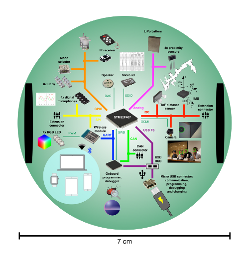
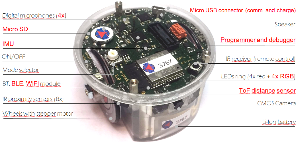
The following figures show the main components offered by the e-puck2 robot and where they are physically placed:
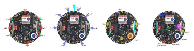
Specifications
The e-puck2 robot maintains full compatibility with its predecessor e-puck (e-puck HWRev 1.3 is considered in the following table):
| Feature
|
e-puck1.3
|
e-puck2
|
Compatibility
|
Additional
|
| Size, weight
|
70 mm diameter, 55 mm height, 150 g
|
Same form factor: 70 mm diameter, 45 mm, 130 g
|

|
No e-jumper required
|
| Battery, autonomy
|
LiIPo rechargeable battery (external charger), 1800 mAh.
About 3 hours autonomy. Recharging time about 2-3h.
|
Same battery; USB charging, recharging time about 2.5h.
|

|
USB charging
|
| Processor
|
16-bit dsPIC30F6014A @ 60MHz (15 MIPS), DSP core for signal processing
|
32-bit STM32F407 @ 168 MHz (210 DMIPS), DSP and FPU, DMA
|
|
~10 times faster
|
| Memory
|
RAM: 8 KB; Flash: 144 KB
|
RAM: 192 KB; Flash: 1024 KB
|
|
RAM: 24x more capable
Flash:~7x more capable
|
| Motors
|
2 stepper motors with a 50:1 reduction gear; 20 steps per revolution; about 0.13 mm resolution
|
Same motors
|
|
|
| Wheels
|
Wheels diamater = 41 mm
Distance between wheels = 53 mm
|
Same wheels
|
|
|
| Speed
|
Max: 1000 steps/s (about 12.9 cm/s)
|
Max: 1200 steps/s (about 15.4 cm/s)
|
|
20% faster
|
| Mechanical structure
|
Transparent plastic body supporting PCBs, battery and motors
|
Same mechanics
|
|
|
| Distance sensor
|
8 infra-red sensors measuring ambient light and proximity of objects up to 6 cm
|
Same infra-red sensors
Front real distance sensor, Time of fight (ToF), up to 2 meter.
|
|
ToF sensor
|
| IMU
|
3D accelerometer and 3D gyro
|
3D accelerometer, 3D gyro, 3D magnetometer
|
|
3D magnetometer
|
| Camera
|
VGA color camera; typical use: 52x39 or 480x1
|
Same camera; typical use: 160x120
|
|
Bigger images handling
|
| Audio
|
3 omni-directional microphones for sound localization
speaker capable of playing WAV or tone sounds
|
4 omni-directional microhpones (digital) for sound localization
speaker capable of playing WAV or tone sounds
|
|
+1 front microphone
|
| LEDs
|
8 red LEDs around the robot, green body light, 1 strong red LED in front
|
4 red LEDs and 4 RGB LEDs around the robot, green light, 1 strong red LED in front
|
|
4x RGB LEDs
|
| Communication
|
RS232 and Bluetooth 2.0 for connection and programming
|
USB Full-speed, Bluetooth 2.0, BLE, WiFi
|
|
WiFi, BLE
|
| Storage
|
Not available
|
Micro SD slot
|
|
Micro SD
|
| Remote Control
|
Infra-red receiver for standard remote control commands
|
Same receiver
|
|
|
| Switch / selector
|
16 position rotating switch
|
Same selector
|
|
|
| Extensions
|
Ground sensors, range and bearing, RGB panel, Gumstix extension, omnivision, your own
|
All extension supported
|
|
|
| Programming
|
Free C compiler and IDE, Webots simulator, external debugger
|
Free C compiler and IDE, Webots simulator, onboard debugger (GDB)
|
|
Onboard debugger
|
This is the overall communication schema:
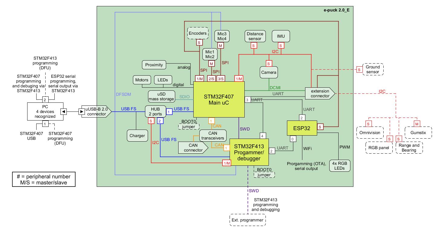
Documentation
- From about July 2019, the camera mounted on the e-puck2 robot is the Omnivision OV7670 CMOS image sensor, datasheet
Migrating from e-puck1.x to e-puck2
The e-puck2 robot maintains full compatibility with its predecessor e-puck, but there are some improvements that you should be aware of.
First of all the e-jumper, that is the small board that is attached on top of the e-puck1.x, isn't anymore needed in the e-puck2. The components available on the e-jumper are integrated directly in the robot board. On top of the e-puck2 you'll see a quite big free connector, this is used to attach the extensions board designed for the e-puck1.x that are fully compatible with the e-puck2; you must not connect the e-jumper in this connector.
Secondly you don't need anymore to unplug and plugin the battery for charging, but instead you can charge the battery (up to 1 ampere) directly by connecting the USB cable. If you want you can still charge the battery with the e-puck1.x external charger, in case you have more than one battery.
Moreover you don't need anymore a special serial cable (with probably an RS232 to USB adapter) to be able to communicate with the robot, but you can use the USB cable. Once connected to the computer a serial port will be available that you can use to easily exchange data with the robot.
Extensions
All the extensions (ground sensors, range and bearing, RGB panel, gumstix and omnvision) are supported by the e-puck2 robot, this means that if you have some extensions for the e-puck1.x you can still use them also with e-puck2.
For more information about using the gumstix extension with e-puck2 robot refer to http://www.gctronic.com/doc/index.php?title=Overo_Extension#e-puck2.
Getting Started
The e-puck2 robot features 3 chips onboard:
- the main microcontroller, that is responsible for handling the sensors and actuators and which runs also the demos/algorithms
- the programmer, that provides programming/debugging capabilties and moreover it configures the USB hub and is responsible for the power management (on/off of the robot and battery measure)
- radio module, that is responsible for handling the wireless communication (WiFi, BLE, BT), the RGB LEDs and the user button (the RGB LEDs and button are connected to the radio module due to the pin number limitation on the main microcontroller)
The robot is shipped with the last firmware version programmed on all 3 chips, so you can immediately start using the robot.
The following sections explain the basic usage of the robot, all the users should read this chapter completely in order to have a minimal working system ready to play with the e-puck2 robot. Some sections will have more detailed information that can be read by following the links provided.
When required, dedicated informations are given for all platforms (Windows, Linux, Mac). The commands given for Linux are related to the Ubuntu distribution, similar commands are available in other distributions.
Turn on/off the robot
To turn on the robot you need to press the power button (blue button) placed on the bottom side of the board, near the speaker, as shown in the following figures:
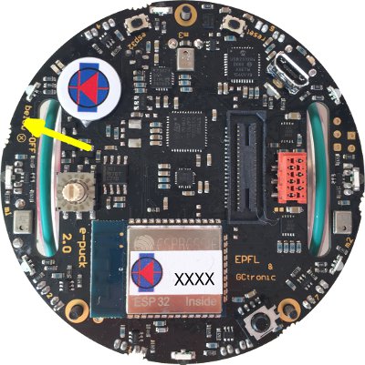
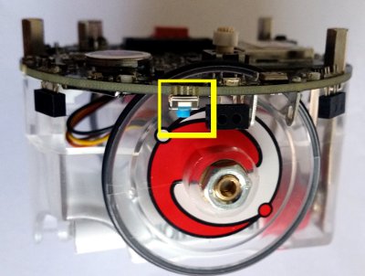
To turn off the robot you need to press the power button for 1 second.
Meaning of the LEDs
The e-puck2 has three groups of LEDs that are not controllable by the user.
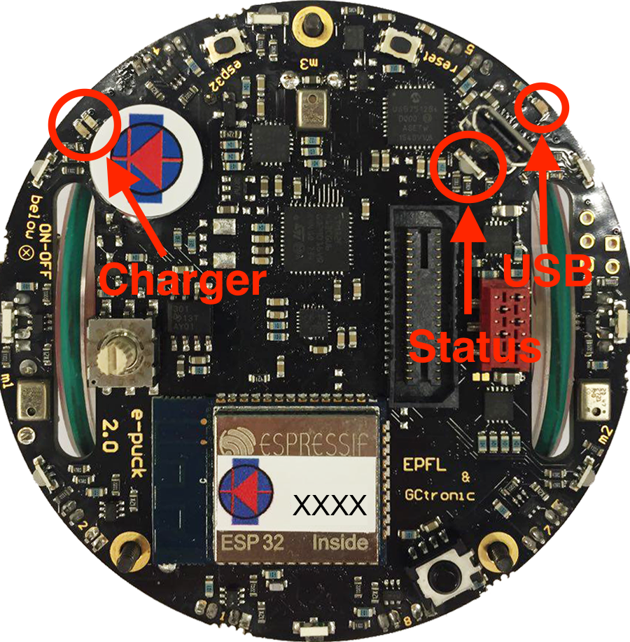
- Top view of the e-puck2
- Charger: RED if charging, GREEN if charge complete and RED and GREEN if an error occurs
- USB: Turned ON if the e-puck2 detects a USB connection with a computer
- STATUS: Turned ON if the robot is ON and OFF if the robot is OFF. When ON, gives an indication of the level of the battery. Also blinks GREEN if the program is running during a debug session.
Battery level indications (STATUS RGB LED):
- GREEN if the system's tension is greater than 3.5V
- ORANGE if the system's tension is between 3.5V and 3.4V
- RED if the system's tension is between 3.4V and 3.3V
- RED blinking if the system's tension is below 3.3V
The robot is automatically turned OFF if the system's tension gets below 3.2V during 10 seconds.
Connecting the USB cable
A micro USB cable (included with the robot in the package) is needed to connect the robot to the computer. There are two connectors, one placed on top of the robot facing upwards and the other placed on the side of the robot, as shown in the following figures. Both can be used to charge the robot (up to 1 ampere) or to communicate with it, but do not connect two cables at the same time. Connect the USB cable where is more comfortable to you.

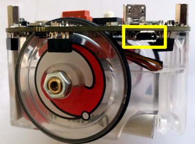
Installing the USB drivers
The USB drivers must be installed only for the users of a Windows version older than Windows 10:
- Download and open zadig-2.3.exe
- Connect the e-puck2 with the USB cable and turn it on. Three unknown devices appear in the device list of the program, namely e-puck2 STM32F407, e-puck2 GDB Server (Interface 0) and e-puck2 Serial Monitor (Interface 2).
- For each of the three devices mentioned above, select the
USB Serial (CDC) driver and click on the Install Driver button to install it. Accept the different prompts which may appear during the process. At the end you can simply quit the program and the drivers are installed. These steps are illustrated on Figure 3 below.
- Note : The drivers installed are located in
C:\Users\"your_user_name"\usb_driver
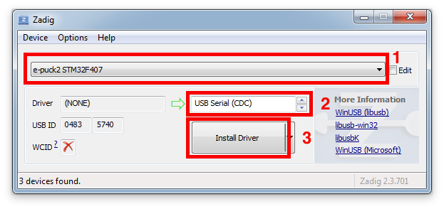
- Example of driver installation for e-puck2 STM32F407
The drivers are automatically installed with Windows 10, Linux and Mac OS.
Anyway in Linux in order to access the serial ports, a little configuration is needed. Type the following command in a terminal session: sudo adduser $USER dialout. Once done, you need to log off to let the change take effect.
Finding the USB serial ports used
Two ports are created by the e-puck2's programmer when the USB cable is connected to the robot (even if the robot is turned off):
- e-puck2 GDB Server. The port used to program and debug the e-puck2.
- e-puck2 Serial Monitor. Serial communication between the PC and the radio module (used also to program the radio module).
A third port could be available depending on the code inside the e-puck2's microcontroller. With the factory firmware a port named e-puck2 STM32F407 is created.
Windows
- Open the Device Manager
- Under Ports (COM & LPT) you can see the virtual ports connected to your computer.
- Do a Right-click -> properties on the COM port you want to identify.
- Go under the details tab and select Bus reported device description in the properties list.
- The name of the port should be written in the text box below.
- Once you found the desired device, you can simply look at its port number (COMX).
Linux
- 1. Open a terminal window (
ctrl+alt+t) and enter the following command: ls /dev/ttyACM*
- 2. Look for ttyACM0 and ttyACM1 in the generated list, which are respectively e-puck2 GDB Server and e-puck2 Serial Monitor. ttyACM2 will be also available with the factory firmware, that is related to e-puck2 STM32F407 port
Note : Virtual serial port numbering on Linux depends on the connections order, thus it can be different if another device using virtual serial ports is already connected to your computer before connecting the robot, but the sequence remains the same.
Mac
- 1. Open a terminal window and enter the following command:
ls /dev/cu.usbmodem*
- 2. Look for two cu.usbmodemXXXX, where XXXX is the number attributed by your computer. You should find two names, with a numbering near to each other, which are respectively e-puck2 GDB Server (lower number) and e-puck2 Serial Monitor (higher number). A third device cu.usbmodemXXXX will be available with the factory firmware, that is related to e-puck2 STM32F407 port
Note : Virtual serial port numbering on Mac depends on the physical USB port used and the device. If you want to keep the same names, you must connect to the same USB port each time.
PC interface
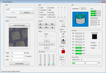
A PC application was developed to start playing with the robot attached to the computer via USB cable: you can have information about all the sensors, receive camera images and control the leds and motors.
Beware that it's not mandatory to download this application in order to work with the robot, but it is a nice demo that gives you an overview of all the sensors and actuators available on the robot, this is a first step to gain confidence with the robot.
With the factory firmwares programmed in the robot, place the selector in position 8, attach the USB cable and turn on the robot. Enter the correct port (the one related to e-puck2 STM32F407) in the interface and click connect.
The source code is available from the repository https://github.com/e-puck2/monitor.
Available executables
On Linux remember to apply the configuration explained in the chapter Installing the USB drivers in order to access the serial port.
Installing the dependencies for firmwares updates
You can update the firmware for all 3 chips: the main microcontroller, the radio module and the programmer. For doing that, you need some tools to be installed on the system.
Windows
To upload a new firmware in the microcontroller or in the radio module, you don't need to install anything, the packages provided include all the dependencies.
To upload a new firmware in the programmer you need to install an application called DfuSe released by STMicroelectronics. You can download it from DfuSe_V3.0.5.zip.
Linux
To upload a new firmware in the microcontroller or in the radio module, you need:
- Python (>= 3.4):
sudo apt-get install python3
- Python pip:
sudo apt-get install -y python3-pip
- pySerial (>= 2.5):
sudo pip3 install pyserial
To upload a new firmware in the programmer you need:
- dfu-util:
sudo apt-get install dfu-util
Mac
Install the Homewbrew package manager by opening a terminal and issueing:
/usr/bin/ruby -e "$(curl -fsSL https://raw.githubusercontent.com/Homebrew/install/master/install)"
and then:
brew upgrade
To upload a new firmware in the microcontroller or in the radio module, you need:
- Python (>= 3.4):
brew install python (it will install also pip)
- pySerial (>= 2.5):
pip3 install pyserial
To upload a new firmware in the programmer you need:
- dfu-util:
brew install dfu-util
PC side development
This section is dedicated to the users that develop algorithms on the PC side and interact with the robot remotely through a predefined communication protocol. These users don't modify the firmware of the robot, but instead they use the factory firmware released with the robot. They update the robot firmware only when there is an official update.
The remote control of the robot, by receiving sensors values and setting the actuators, is done through the following channels: Bluetooth, Bluetooth Low Energy, WiFi, USB cable.
Examples of tools/environment used by these users:
- Aseba
- Simulator (e.g. Webots)
- ROS
- iOS, Android apps
- Custom PC application
- IoT (e.g. IFTTT)
If you fall into this category, then follow this section for more information: PC side development.
Main microcontroller
The e-puck2 robot main microcontroller is a 32-bit STM32F407 that runs at 168 MHz (210 DMIPS) and include DSP, FPU and DMA capabilities. The version chosen for the e-puck2 has 192 KB of total RAM and 1024 KB of flash, so there is a lot of memory to work with.
This chip is responsible for handling the sensors and actuators and runs also the demos and algorithms.
Factory firmware
The main microcontroller of the robot is initially programmed with a firmware that includes many demos that could be started based on the selector position, here is a list of the demos with related position and a small description:
- Selector position 0: Aseba
- Selector position 1: Shell
- Selector position 2: Read proximity sensors and when an object is near a proximity, turn on the corresponding LED
- Selector position 3: Asercom protocol v2 (BT)
- Selector positoin 4: Range and bearing extension (receiver)
- Selector position 5: Range and bearing extension - clustering demo (simultaneous transmitter and receiver).
- Selector position 6: Move the robot back and forth exploiting the gyro, with LEDs animation
- Selector position 7: Play a wav (mono, 16 KHz) named "example.wav" from the micro sd when pressing the button
- Selector position 8: Asercom protocol v2 (USB)
- Selector position 9: Local communication: transceiver
- Selector position 10: this position is used to work with the Linux extensions. To work with gumstix refer to Overo Extension: e-puck2 , to work with Pi-puck refer to Pi-puck: Requirements .
- Selector position 11: Simple obstacle avoidance + some animation
- Selector position 12: Hardware test
- Selector position 13: LEDs reflect orientation of the robot
- Selector position 14: Compass
- Selector position 15: WiFi mode
The pre-built firmware is available here main microcontroller factory firmware (10.12.21).
Firmware update
Now and then there could be an official firmware update for the robot and it's important to keep the robot updated with the last firmware to get possibile new features, improvements and for bug fixes.
The onboard programmer run a GDB server, so we use GDB commands to upload a new firmware, for this reason a toolchain is needed to upload a new firmware to the robot.
The following steps explain how to update the main microcontroller firmware:
1. Download the package containing the required toolchain and script to program the robot: Windows, Linux 32 bits/64 bits, Mac OS
2. Download the last version of the main microcontroller factory firmware (10.12.21), or use your custom firmware
3. Extract the package and put the firmware file (with elf extension) inside the package directory; beware that only one elf file must be present inside this directory
4. Attach the USB cable and turn on the robot
5. Run the script from the package directory:
- Windows: double click
program.bat
- Linux/Mac: issue the following command in a terminal
./program.sh. If you get permission errors, then issue sudo chmod +x program.sh to let the script be executable.
When the upload is complete you'll see an output like in the following figure:
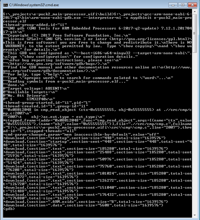
The final lines should contain the entry ".data",, this means that the upload was successfull. You can then close the terminal window if it is still open.
If you encounter some problem, try to unplug and plug again the USB cable and power cycle the robot, then retry.
Robot side development
If you are an embedded developer and are brave enough, then you have complete access to the source code running on the robot, so you can discover what happen inside the main microcontroller and modify it to accomodate your needs. Normally the users that fall into this category develop algorithms optimized to run directly on the microcontroller, such as:
- onboard image processing
- swarm algorithms
- fully autonomous behaviors
- ...
For more information about programming the robot itself, refer to section Robot side development
Radio module
The radio module chosen for the e-puck is the new ESP32 chip from Espressif, integrating a dual core that run up to 240 MHz, 4 MB of flash and 520 KB of RAM. It supports WiFi standards 802.11 b/g/n (access point mode supported), Bluetooth and Bluetooth LE 4.2. It is the successor of the ESP8266 chip. The following figure shows the various peripherals available on the ESP32:
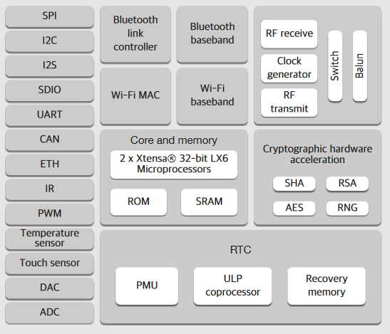
This chip first of all is responsible for handling the wireless communication, moreover it handles also the RGB LEDs (with PWM) and the user button. The RGB LEDs and button are connected to the radio module due to the pin number limitation on the main microcontroller.
Factory firmware
The radio module of the robot is initially programmed with a firmware that supports Bluetooth communication.
The pre-built firmware is available here radio module factory firmware (11.12.18).
WiFi firmware
At the moment the factory firmware supports only Bluetooth, if you want to work with WiFi you need to program the radio with a dedicated firmware, refer to section PC side development: WiFi.
BLE firmware
At the moment the factory firmware supports only calssic Bluetooth, if you want to work with Bluetooth Low Energy you need to program the radio with a dedicated firmware, refer to section Mobile phone development.
Firmware update
In order to update the firmware of the ESP32 WiFi module you need to use a python script called esptool provided by Espressif (manufacturer of the chip). This script was modified to work with the e-puck2 robot and is included in the provided package. The following steps explain how to update the radio module firmware:
1. Download the package containing the required tools and script to program the robot: Windows, Linux / Mac
2. Download the last version of the radio module factory firmware (11.12.18), or use another firmware (e.g. WiFi, BLE, your own). The firmware is composed by 3 files named bootloader.bin, ESP32_E-Puck_2.bin and partitions_singleapp.bin
3. Extract the package and put the firmware files inside the package directory; beware that the name of the .bin files must be the same as indicated in step 2
4. Attach the USB cable and turn on the robot
5. Run the script from the package directory:
- Windows: double click
program.bat
- Linux/Mac: issue the following command in a terminal
./program.sh. If you get permission errors, then issue sudo chmod +x program.sh to let the script be executable.
The upload should last about 10-15 seconds and you'll see the progress as shown in the following figure:
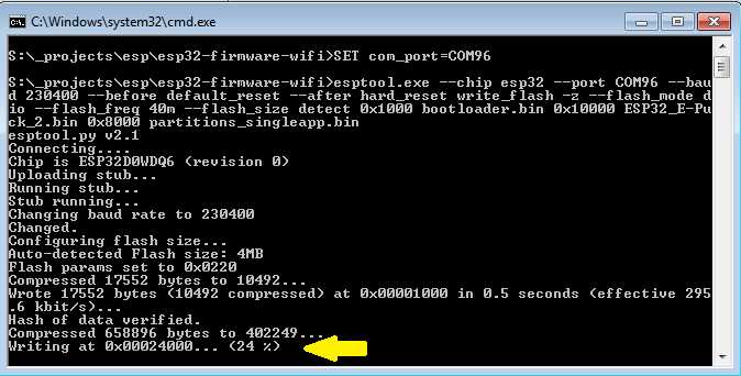
When the upload is complete you'll see that all 3 bin files are uploaded correctly as shown in the following figure:
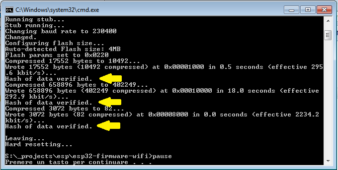
Sometime you could encounter a timeout error as shown in the following figures; in these cases you need to unplug and plug again the USB cable and power cycle the robot, then you can retry.
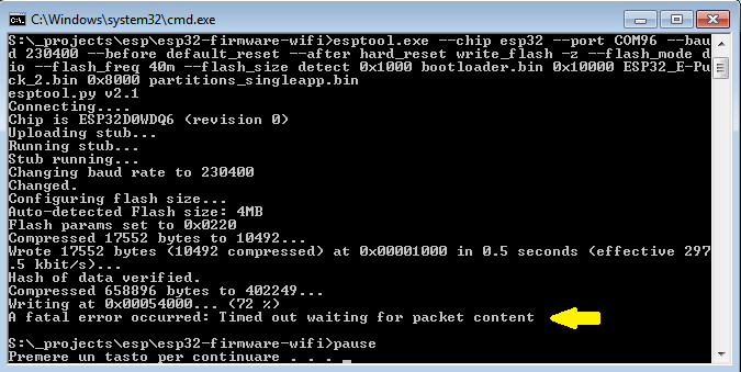
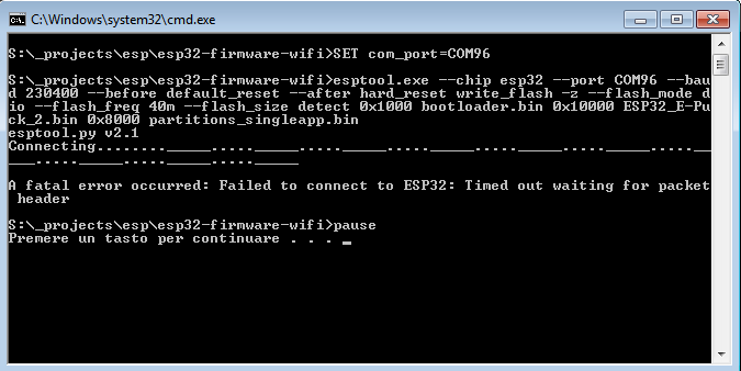
Development
Probably, you'll never need to touch the firmware running in the radio module, but in case you need to modify the code or you're simply curious about what is happening at the low level, then refer to the section Radio module development.
Programmer
The e-puck2 robot is equipped with an onboard programmer and debugger that let you update the firmware of the robot and debug your code easily using a standard USB interface. There is a dedicated STM32F413 microcontroller that acts as the programmer with built in GDB server, so you can control exactly what happens using the GNU Project Debugger in your host machine.
The programmer microcontroller is also in charge of handling various low level features such as the configuration of the USB hub and the power button.
Factory firmware
The programmer is initially programmed with a firmware based on a modified version of Black Magic Probe programmer/debugger.
The pre-built firmware is available here programmer-firmware.bin (28.05.20); it is also available in dfu format here programmer-firmware.dfu (28.05.20).
Firmware update
The programmer's microcontroller features a factory bootloader that can be entered by acting on some special pins, the bootloader mode is called DFU (device firmware upgrade). You can enter DFU mode by contacting two pinholes together while inserting the USB cable (no need to turn on the robot). The two pin holes are located near the USB connector of the e-puck2, see the photo below.
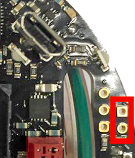
- Location of the pin holes to put the programmer into DFU
The programmer will be recognized as STM Device in DFU Mode device.
Note for Windows users: the device should be recognized automatically (in all Windows versions), but in case it won't be detected then you need to install a libusbK driver for the DFU device.
Follow the same procedure as explained in section Installing the USB drivers using libusbK driver instead of USB Serial (CDC).
Note for users having robots id >= 5400: the procedure is slightly different, please contact us if you really need to update the programmer firmware.
Linux/Mac
In order to update the programmer firmware you need an utility called dfu-util, it should be already installed from section Installing the dependencies for firmwares updates.
To uplaod the firmware, issue the following command: sudo dfu-util -d 0483:df11 -a 0 -s 0x08000000 -D programmer-firmware.bin
Windows
Start the DfuSe application (previously installed from section Installing the dependencies for firmwares updates). The programmer in DFU mode will be automatically detected as shown in figure 1. Then you need to open the compiled firmware by clicking on choose and then locating the file with dfu extension, as shown in figure 2. Now click on the upgrade button, a warning message will be shown, confirm the action by clicking on yes as shown in figure 3. If all is ok you'll be prompted with a message saying that the upgrade was successfull as shown in figure 4.
Development
The programmer code shouldn't be modified, but if you know what you're doing then refer to section Programmer development.