Pi-puck and Elisa-3: Difference between pages
| Line 1: | Line 1: | ||
=Overview= | |||
<span class="plainlinks">[http://www.gctronic.com/doc/images/Elisa3_and_charger.JPG <img width=350 src="http://www.gctronic.com/doc/images/Elisa3_and_charger.JPG">]</span> <br/> | |||
Elisa-3 is an evolution of the [http://www.gctronic.com/doc/index.php/Elisa Elisa] robot based on a different microcontroller and including a comprehensive set of sensors: | |||
* [http://www.atmel.com/dyn/products/product_card.asp?part_id=3632 Atmel 2560] microcontroller (Arduino compatible) | |||
* central RGB led | |||
* 8 green leds around the robot | |||
* IRs emitters | |||
* 8 IR proximity sensors ([http://www.vishay.com/docs/83752/tcrt1000.pdf Vishay Semiconductors Reflective Optical Sensor]) | |||
* 4 ground sensors ([http://www.fairchildsemi.com/ds/QR/QRE1113.pdf Fairchild Semiconductor Minature Reflective Object Sensor]) | |||
* 3-axis accelerometer ([http://www.freescale.com/files/sensors/doc/data_sheet/MMA7455L.pdf Freescale MMA7455L]) | |||
* RF radio for communication ([http://www.nordicsemi.com/kor/Products/2.4GHz-RF/nRF24L01P Nordic Semiconductor nRF24L01+]) | |||
* micro USB connector for programming, debugging and charging | |||
* IR receiver | |||
* 2 DC motors | |||
* top light diffuser | |||
* selector | |||
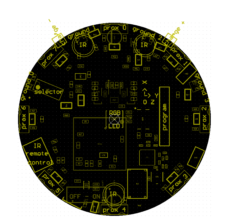
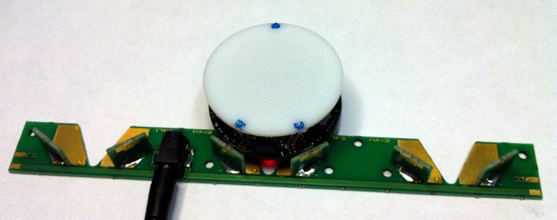
The robot is able to self charge using the charger station, as shown in the previous figure. The following figure illustrates the position of the various sensors: <br/> | |||
<span class="plainlinks">[http://www.gctronic.com/doc/images/Elisa3-mainComp-digital-white.png <img width=400 src="http://www.gctronic.com/doc/images/Elisa3-mainComp-digital-white.png">]</span> | |||
==Useful information== | |||
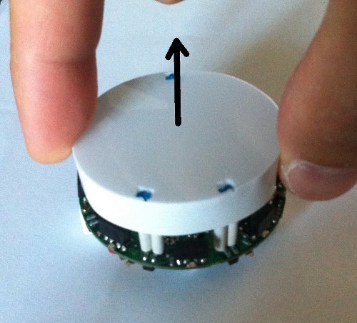
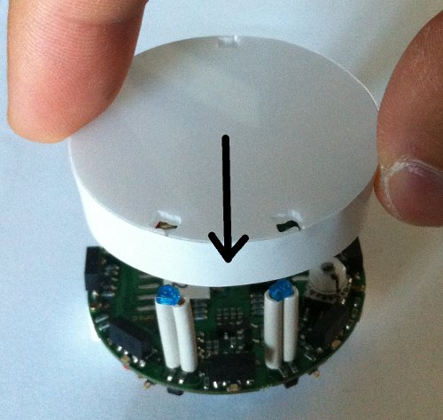
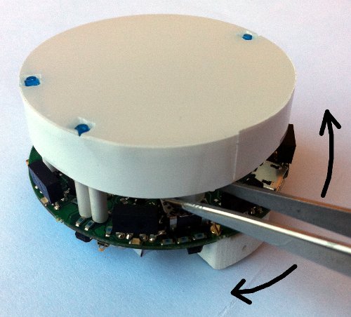
* the top light diffuser and robot are designed to lock together, but the diffuser isn't fixed and can thus be removed as desired; the top light diffuser, as the name suggests, helps the light coming from the RGB led to be smoothly spread out, moreover the strip attached around the diffuser let the robot be better detected from others robots. Once the top light diffuser is removed, pay attention not to look at the RGB led directly. In order to remove the top light diffuser simply pull up it, then to place it back on top of the robot remember to align the 3 holes in the diffuser with the 3 IRs emitters and push down carefully untill the diffuser is stable; pay attention to not apply too much force on the IRs emitters otherwise they can bend and stop working. | |||
<span class="plainlinks">[http://www.gctronic.com/doc/images/Diffuser-pull-up.jpg <img width=200 src="http://www.gctronic.com/doc/images/Diffuser-pull-up.jpg">]</span> | |||
<span class="plainlinks">[http://www.gctronic.com/doc/images/Diffuser-push-down.jpg <img width=200 src="http://www.gctronic.com/doc/images/Diffuser-push-down.jpg">]</span><br/> | |||
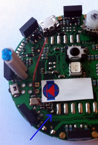
* when the top light diffuser is fit on top of the robot, then in order to change the selector position you can use the tweezers; the selector is located near the front-left IR emitter, as shown in the following figure: | |||
<span class="plainlinks">[http://www.gctronic.com/doc/images/selector-tweezers.jpg <img width=200 src="http://www.gctronic.com/doc/images/selector-tweezers.jpg">]</span> | |||
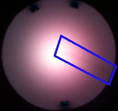
* if you encounter problems with the radio communication (e.g. lot of packet loss) then you can try moving the antenna that is a wire near the robot label. Place the antenna as high as possible, near the plastic top light diffuser; try placing it in the borders in order to avoid seeing a black line on the top light diffuser when the RGB led is turned on. | |||
<span class="plainlinks">[http://www.gctronic.com/doc/images/Antenna-position.jpg <img width=200 src="http://www.gctronic.com/doc/images/Antenna-position.jpg">]</span> | |||
<span class="plainlinks">[http://www.gctronic.com/doc/images/Antenna-diffuser.jpg <img width=200 src="http://www.gctronic.com/doc/images/Antenna-diffuser.jpg">]</span> | |||
==Robot charging== | |||
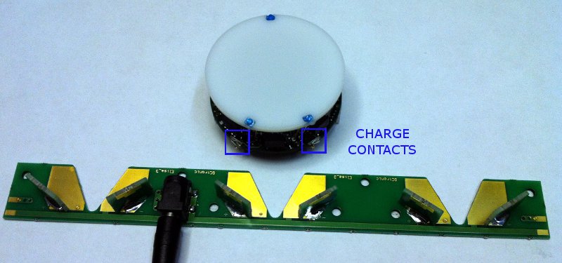
The Elisa-3 can be piloted in the charger station in order to be automatically self charged; there is no need to unplug the battery for charing. The following figures shows the robot approaching the charger station; a led indicates that the robot is in charge: | |||
<br/> | |||
<span class="plainlinks">[http://www.gctronic.com/doc/images/Elisa3-charger-out.jpg <img width=300 src="http://www.gctronic.com/doc/images/Elisa3-charger-out.jpg">]</span> | |||
<span class="plainlinks">[http://www.gctronic.com/doc/images/Elisa3-charger-in.jpg <img width=350 src="http://www.gctronic.com/doc/images/Elisa3-charger-in.jpg">]</span> <br/> | |||
The microcontroller is informed when the robot is in charge and this information is also transferred to the PC in the ''flags'' byte; this let the user be able to pilote the robot to the charger station and be informed when it is actually in charge. More information about the radio protocol can be found in the section [http://www.gctronic.com/doc/index.php/Elisa-3#Communication Communication]. | |||
Moreover the robot is also charged when the micro USB cable is connected to a computer; pay attention that if the USB cable is connected to a hub, this one need to be power supplied. | |||
The following video shows the Elisa-3 piloted through the radio to the charging station using the monitor application: {{#ev:youtube|kjliXlQcgzw}} | |||
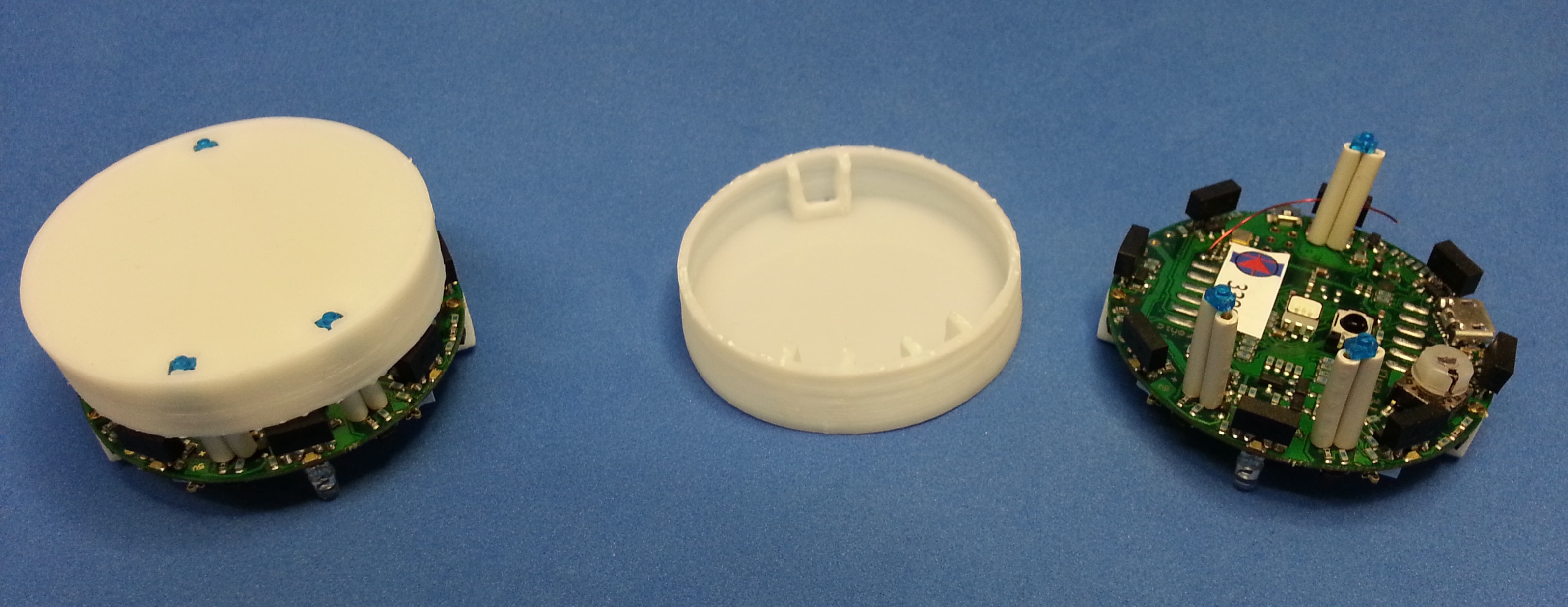
==Top light diffuser== | |||
From February 2013 onwards the Elisa-3 is equipped with a new top light diffuser designed to fit perfectly in the 3 IRs emitters of the robot. The diffuser is made of plastic (3d printed), it is more robust and it simplifies the removal and insertion. Here is an image:<br/> | |||
<span class="plainlinks">[http://www.gctronic.com/doc/images/elisa3-new-case.jpg <img width=350 src="http://www.gctronic.com/doc/images/elisa3-new-case-small.jpg">]</span> | |||
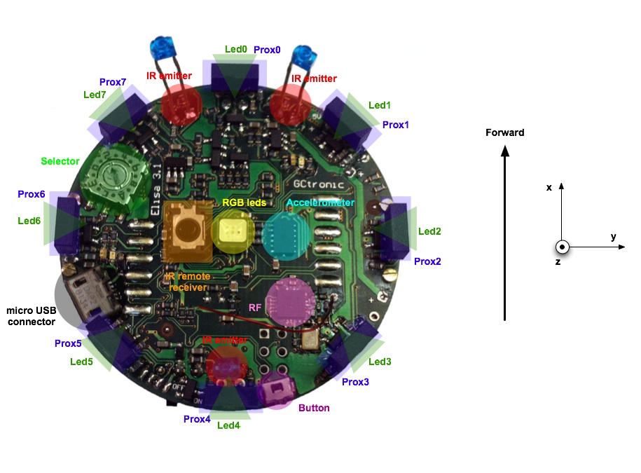
=Hardware= | =Hardware= | ||
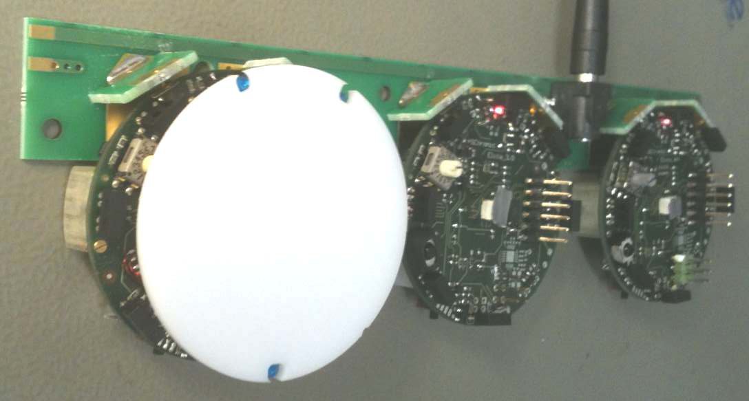
The following figures show the main components offered by the Elisa-3 robot and where they are physically placed: <br/> | |||
<span class="plainlinks">[ | <span class="plainlinks">[http://www.gctronic.com/doc/images/Elisa3.1-hw-schema-top.jpg <img width=550 src="http://www.gctronic.com/doc/images/Elisa3.1-hw-schema-top.jpg">]</span> <br/> | ||
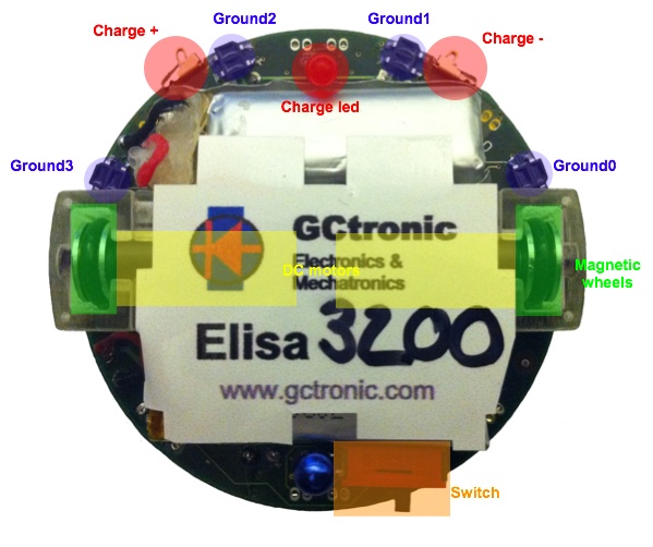
<span class="plainlinks">[http://www.gctronic.com/doc/images/Elisa3-hw-schema-bottom3.jpg <img width=400 src="http://www.gctronic.com/doc/images/Elisa3-hw-schema-bottom3.jpg">]</span> <br/> | |||
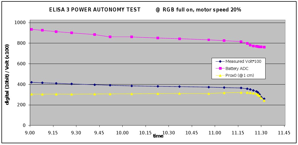
== | ==Power autonomy== | ||
The robot is equipped with two batteries for a duration of about 3 hours at normal usage (motors run continuously, IRs and RGB leds turned on). | |||
<span class="plainlinks">[ | <span class="plainlinks">[http://www.gctronic.com/doc/images/Power-autonomy.jpg <img width=800 src="http://www.gctronic.com/doc/images/Power-autonomy.jpg">]</span> <br/> | ||
= | ==Detailed specifications== | ||
{| border="1" | |||
|'''Feature''' | |||
|'''Technical information''' | |||
|- | |||
|Size, weight | |||
|50 mm diameter, 30 mm height, 39 g | |||
|- | |||
|Battery, autonomy | |||
|LiIPo rechargeable battery (2 x 130 mAh, 3.7 V). About 3 hours autonomy. Recharging time about 1h e 30. | |||
|- | |||
|Processor | |||
|Atmel ATmega2560 @ 8MHz (~ 8 MIPS); 8 bit microcontroller | |||
|- | |||
|Memory | |||
|RAM: 8 KB; Flash: 256 KB; EEPROM: 4 KB | |||
|- | |||
|Motors | |||
|2 DC motors with a 25:1 reduction gear; speed controlled with backEMF | |||
|- | |||
|Magnetic wheels | |||
|Adesion force of about 1 N (100 g) depending on surface material and painting<br/> Wheels diamater = 9 mm <br/>Distance between wheels = 40.8 mm | |||
|- | |||
|Speed | |||
|Max: 60 cm/s | |||
|- | |||
|Mechanical structure | |||
|PCB, motors holder, top white plastic to diffuse light | |||
|- | |||
|IR sensors | |||
|8 infra-red sensors measuring ambient light and proximity of objects up to 6 cm; each sensor is 45° away from each other <br/> 4 ground sensors detecting the end of the viable surface (placed on the front-side of the robot) | |||
|- | |||
| IR emitters | |||
| 3 IR emitters (2 on front-side, 1 on back-side of the robot) | |||
|- | |||
|Accelerometer | |||
|3D accelerometer along the X, Y and Z axis | |||
|- | |||
|LEDs | |||
|1 RGB LED in the center of the robot; 8 green LEDs around the robot | |||
|- | |||
|Switch / selector | |||
|16 position rotating switch | |||
|- | |||
|Communication | |||
| Standard Serial Port (up to 38kbps)<br/> Wireless: RF 2.4 GHz; the throughput depends on number of robot: eg. 250Hz for 4 robots, 10Hz for 100 robots; up to 10 m | |||
|- | |||
|Remote Control | |||
|Infra-red receiver for standard remote control commands | |||
|- | |||
|Expansion bus | |||
|Optional connectors: 2 x UART, I2C, 2 x PWM, battery, ground, analog and digital voltage | |||
|- | |||
|Programming | |||
|C/C++ programming with the AVR-GCC compiler ([http://winavr.sourceforge.net/ WinAVR] for Windows). Free compiler and IDE (AVR Studio / Arduino) | |||
|} | |||
The | =Communication= | ||
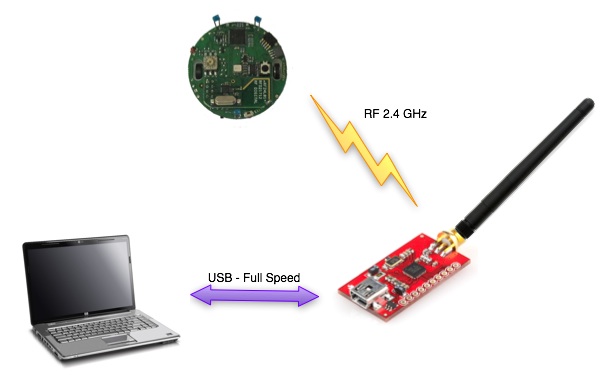
==Wireless== | |||
The radio base-station is connected to the PC through USB and transfers data to and from the robot wirelessly. In the same way the radio chip ([http://www.nordicsemi.com/eng/Products/2.4GHz-RF/nRF24L01P nRF24L01+]) mounted on the robot communicates through SPI with the microcontroller and transfers data to and from the PC wirelessly.<br/> | |||
The robot is identified by an address that is stored in the last two bytes of the microcontroller internal EEPROM; the robot firmware setup the radio module reading the address from the EEPROM. This address corresponds to the robot id written on the label placed under the robot and should not be changed.<br/> | |||
<span class="plainlinks">[http://www.gctronic.com/doc/images/Elisa-communication.jpg <img width=400 src="http://www.gctronic.com/doc/images/Elisa-communication.jpg">]</span><br/> | |||
===Packet format - PC to radio to robot=== | |||
The | The 13 bytes payload packet format is shown below (the number in the parenthesis expresses the bytes): | ||
{| border="1" | |||
| Command (1) | |||
| Red led (1) | |||
| Blue led (1) | |||
| Green led (1) | |||
| IR + Flags (1) | |||
| Right motor (1) | |||
| Left motor (1) | |||
| Small green leds (1) | |||
| Flags2 (1) | |||
| Remaining 5 bytes are unused | |||
|} | |||
== | * Command: 0x27 = change robot state; 0x28 = goto base-station bootloader (this byte is not sent to the robot) | ||
* Red, Blue, Green leds: values from 0 (OFF) to 100 (ON max power) | |||
* IR + flags: | |||
** first two bits are dedicated to the IRs: | |||
*** 0x00 => all IRs off | |||
*** 0x01 => back IR on | |||
*** 0x02 => front IRs on | |||
*** 0x03 => all IRs on | |||
** third bit is reserved for enabling/disabling IR remote control (0=>disabled, 1=>enabled) | |||
** fourth bit is used for sleep (1 => go to sleep for 1 minute) | |||
** fifth bit is used to calibrate all sensors (proximity, ground, accelerometer) and reset odometry | |||
** sixth bit is reserved (used by radio station) | |||
** seventh bit is used for enabling/disabling onboard obstacle avoidance | |||
** eight bit is used for enabling/disabling onboard cliff avoidance | |||
* Right, Left motors: speed expressed in 1/5 of mm/s (i.e. a value of 10 means 50 mm/s); MSBit indicate direction: 1=forward, 0=backward; values from 0 to 127 | |||
* Small green leds: each bit define whether the corresponding led is turned on (1) or off (0); e.g. if bit0=1 then led0=on | |||
* Flags2: | |||
** bit0 is used for odometry calibration | |||
** remaining bits unused | |||
* Remaining bytes free to be used | |||
=== | ====Optimized protocol==== | ||
The | The communication between the pc and the base-station is controlled by the master (computer) that continuously polls the slave (base-station); the polling is done once every millisecond and this is a restriction on the maximum communication throughput. To overcome this limitation we implemented an optimized protocol in which the packet sent to the base-station contains commands for four robots simultaneously; the base-station then separate the data and send them to the correct robot address. The same is applied in reception, that is the base-station is responsible of receiving the ack payloads of 4 robots (64 bytes in total) and send them to the computer. This procedure let us have a throughput 4 times faster. | ||
<!-- | |||
- ack returned must be up to 16 bytes (max 64 bytes for the usb buffer); the same number of bytes returned by the robot as ack payload has to be read then by the pc!! | |||
- la base-station ritorna "2" quando l'ack non è stato ricevuto; | |||
--> | |||
===Packet format - robot to radio to PC=== | |||
The robot send back to the base-station information about all its sensors every time it receive a command; this is accomplished by using the "ack payload" feature of the radio module. Each "ack payload" is 16 bytes length and is marked with an ID that is used to know which information the robot is currently transferring. The sequence is the following (the number in the parenthesis expresses the bytes): | |||
{| border="1" | |||
|ID=3 (1) | |||
|Prox0 (2) | |||
|Prox1 (2) | |||
|Prox2 (2) | |||
|Prox3 (2) | |||
|Prox5 (2) | |||
|Prox6 (2) | |||
|Prox7 (2) | |||
|Flags (1) | |||
|- | |||
||||||||||||||||| | |||
|- | |||
|ID=4 (1) | |||
|Prox4 (2) | |||
|Ground0 (2) | |||
|Ground1 (2) | |||
|Ground2 (2) | |||
|Ground3 (2) | |||
|AccX (2) | |||
|AccY (2) | |||
|TV remote (1) | |||
|- | |||
||||||||||||||||| | |||
|- | |||
|ID=5 (1) | |||
|ProxAmbient0 (2) | |||
|ProxAmbient1 (2) | |||
|ProxAmbient2 (2) | |||
|ProxAmbient3 (2) | |||
|ProxAmbient5 (2) | |||
|ProxAmbient6 (2) | |||
|ProxAmbient7 (2) | |||
|Selector (1) | |||
|- | |||
||||||||||||||||| | |||
|- | |||
|ID=6 (1) | |||
|ProxAmbient4 (2) | |||
|GroundAmbient0 (2) | |||
|GroundAmbient1 (2) | |||
|GroundAmbient2 (2) | |||
|GroundAmbient3 (2) | |||
|AccZ (2) | |||
|Battery (2) | |||
|Free (1) | |||
|- | |||
||||||||||||||||| | |||
|- | |||
|ID=7 (1) | |||
|LeftSteps (4) | |||
|RightSteps (4) | |||
|theta (2) | |||
|xpos (2) | |||
|ypos (2) | |||
|Free (1) | |||
| | |||
| | |||
|} | |||
Pay attention that the base-station could return "error" codes in the first byte if the communication has problems: | |||
* 0 => transmission succeed (no ack received though) | |||
* 1 => ack received (should not be returned because if the ack is received, then the payload is read) | |||
* 2 => transfer failed | |||
Packet ID 3: | |||
* Prox* contain values from 0 to 1023, the greater the values the nearer the objects to the sensor | |||
* The ''Flags'' byte contains these information: | |||
** bit0: 0 = robot not in charge; 1 = robot in charge | |||
** bit1: 0 = button pressed; 1 = button not pressed | |||
** bit2: 0 = robot not charged completely; 1 = robot charged completely | |||
** the remainig bits are not used at the moment | |||
Packet ID 4: | |||
* Prox4 contains values from 0 to 1023, the greater the values the nearer the objects to the sensor | |||
* Ground* contain values from 512 to 1023, the smaller the value the darker the surface | |||
* AccX and AccY contain raw values of the accelerometer; the range is between -64 to 64 | |||
* TV remote contains the last interpreted command received through IR | |||
Packet ID 5: | |||
* ProxAmbient* contain values from 0 to 1023, the smaller the values the brighter the ambient light | |||
* Selector contains the value of the current selector position | |||
Packet ID 6: | |||
* ProxAmbient4 contains values from 0 to 1023, the smaller the values the brighter the ambient light | |||
* GroundAmbient* contain values from 0 to 1023, the smaller the values the brighter the ambient light | |||
* AccZ contains raw values of the accelerometer; the range is between 0 and -128 (upside down) | |||
* Battery contains the sampled value of the battery, the values range is between 780 (battery discharged) and 930 (battery charged) | |||
Packet ID 7: | |||
* LeftSteps and RightSteps contain the sum of the sampled speed for left and right motors respectively (only available when the speed controller isn't used; refer to xpos, ypos and theta when the speed controller is used) | |||
* theta contains the orientation of the robot expressed in 1/10 of degree (3600 degrees for a full turn); available only when the speed controller is enabled | |||
* xpos and ypos contain the position of the robot expressed in millimeters; available only when the speed controller is enabled | |||
==USB cable== | |||
You can directly connect the robot to the computer to make a basic functional test. You can find the source code in the following link [https://projects.gctronic.com/elisa3/Elisa3-global-test.zip Elisa3-global-test.zip] (Windows).<br/> | |||
To start the test follow these steps: | |||
# put the selector in position 6 | |||
# connect the robot to the computer with the USB cable and turn it on | |||
# run the program, insert the correct COM port and choose option 1 | |||
== | =Software= | ||
= | ==Robot== | ||
===Requirements=== | |||
In order to communicate with the robot through the micro USB the FTDI driver need to be installed. If a serial port is automatically created when connecting the robot to the computer you're done otherwise you need to download the drivers for your system and architecture: | |||
* [http://www.ftdichip.com/Drivers/CDM/CDM%20v2.10.00%20WHQL%20Certified.exe Windows Vista/XP], [http://www.ftdichip.com/Drivers/CDM/CDM%20v2.12.10%20WHQL%20Certified.exe Windows 7/8/10 (run as administrator)] | |||
* Ubuntu: when the robot is connected the port will be created in <code>/dev/ttyUSB0</code> (no need to install a driver) | |||
* [http://www.ftdichip.com/drivers/VCP/MacOSX/FTDIUSBSerialDriver_v2_2_18.dmg Mac OS X 10.3 to 10.8 (32 bit)], [http://www.ftdichip.com/Drivers/VCP/MacOSX/FTDIUSBSerialDriver_v2_2_18.dmg Mac OS X 10.3 to 10.8 (64 bit)], [http://www.ftdichip.com/Drivers/VCP/MacOSX/FTDIUSBSerialDriver_v2_3.dmg Mac OS X 10.9 and above]; after installing the driver the port will be created in <code>/dev/tty.usbserial-...</code>; you can find a guide on how to install the driver in the following link [http://www.ftdichip.com/Support/Documents/AppNotes/AN_134_FTDI_Drivers_Installation_Guide_for_MAC_OSX.pdf AN_134_FTDI_Drivers_Installation_Guide_for_MAC_OSX.pdf] | |||
All the drivers can be found in the official page from the following link [http://www.ftdichip.com/Drivers/VCP.htm FTDI drivers]. | |||
== | ===AVR Studio 4 project=== | ||
The projects are built with [https://projects.gctronic.com/elisa3/AvrStudio4Setup.exe AVR Studio 4] released by Atmel. <br/> | |||
The projects should be compatible also with newer versions of Atmel Studio, the last version is available from [https://www.microchip.com/mplab/avr-support/avr-and-sam-downloads-archive https://www.microchip.com/mplab/avr-support/avr-and-sam-downloads-archive]. <br/> | |||
=== | ====Basic demo==== | ||
This project is thought to be a starting point for Elisa-3 newbie users and basically contains a small and clean main with some basic demos selected through the hardware selector that show how to interact with robot sensors and actuators. | |||
The project source can be downloaded from the repository [https://github.com/gctronic/elisa3_firmware_basic https://github.com/gctronic/elisa3_firmware_basic]; the hex file can be directly downloaded from [https://projects.gctronic.com/elisa3/elisa3-firmware-basic_ffb3947_21.03.18.hex Elisa-3 basic firmware hex]. To program the robot refer to section [http://www.gctronic.com/doc/index.php/Elisa-3#Programming Programming]. <br/> | |||
Selector position and related demo: | |||
* 0: no speed controller activated => free running (all others positions have the speed controller activated) | |||
* 1: obstacle avoidance enabled | |||
* 2: cliff avoidance enabled (currently it will simply stop before falling and stay there waiting for commands) | |||
* 3: both obstacle and cliff avoidance enabled | |||
* 4: random RGB colors and small green leds on | |||
* 5: robot moving forward with obstacle avoidance enabled and random RGB colors | |||
====Advanced demo==== | |||
This is an extension of the ''basic demo project'', basically it contains some additional advanced demos. | |||
The project source can be downloaded from the repository [https://github.com/gctronic/elisa3_firmware_advanced.git https://github.com/gctronic/elisa3_firmware_advanced.git]; the hex file can be directly downloaded from [https://projects.gctronic.com/elisa3/elisa3-firmware-advanced_96c355a_13.03.18.hex Elisa-3 advanced firmware hex]. To program the robot refer to section [http://www.gctronic.com/doc/index.php/Elisa-3#Programming Programming]. <br/> | |||
* | Selector position and related demo: | ||
* | * 0: no speed controller activated => free running (all others positions have the speed controller activated) | ||
* | * 1: obstacle avoidance enabled | ||
* | * 2: cliff avoidance enabled (currently it will simply stop before falling and stay there waiting for commands) | ||
* | * 3: both obstacle and cliff avoidance enabled | ||
** | * 4: random RGB colors and small green leds on | ||
** | * 5: robot moving forward with obstacle avoidance enabled and random RGB colors | ||
* 6: robot testing and address writing through serial connection (used in production) | |||
* | * 7: automatic charging demo (refer to section [http://www.gctronic.com/doc/index.php/Elisa-3#Videos Videos]), that is composed of 4 states: | ||
** random walk with obstacle avoidance | |||
** search black line | |||
** follow black line that lead to the charging station | |||
** charge for a while | |||
* 8: autonomous odometry calibration (refer to section [http://www.gctronic.com/doc/index.php/Elisa-3#Autonomous_calibration Autonomous calibration]) | |||
* 9: write default odometry calibration values in EEPROM (hard-coded values); wait 2 seconds before start writing the calibration values | |||
* 10: robot moving forward (with pause) and obstacle avoidance enabled; random RGB colors and green led effect | |||
* 11: local communication: robot alignment | |||
* 12: local communication: 2 or more robots exchange data sequentially | |||
* 13: local communication: listen and transmit continuously; when data received change RGB color | |||
* 14: local communication: RGB color propagation | |||
* 15: clock calibration (communicate with the PC through the USB cable to change the OSCCAL register); this position could also be used to remote contol the robot through the radio (only speed control is enabled) | |||
====Atmel Studio 7==== | |||
If you are working with Atmel Studio 7, you can simply use the provided AVR Studio 4 projects by importing them directly in Atmel Studio 7: <code>File => Import => AVR Studio 4 Project</code>, then select <code>Elisa3-avr-studio.aps</code> and click on <code>Convert</code>. | |||
===Arduino IDE project=== | |||
The project is built with the Arduino IDE 1.x freely available from the [http://arduino.cc/ official Arduino website]. In order to build the Elisa-3 firmware with the Arduino IDE 1.x the following steps has to be performed:<br/> | |||
*1. download the [http://arduino.cc/hu/Main/Software Arduino IDE 1.x] (the last known working version is 1.8.9, refer to [https://www.arduino.cc/en/Main/OldSoftwareReleases#previous Arduino Software]) and extract it, let say in a folder named <code>arduino-1.x</code><br/> | |||
*2. download the [https://projects.gctronic.com/elisa3/elisa3_arduino_library_13.03.18_691e478.zip Elisa-3 library] and extract it within the libraries folder of the Arduino IDE, in this case <code>arduino-1.x\libraries</code>; you should end up with a <code>Elisa3</code> folder within the libraries. If you start the Arduino IDE now you can see that the <code>Elisa-3</code> library is available in the menu <code>Sketch=>Import Library...</code> (or <code>Sketch=>Include Lirary</code> in later IDE versions)<br/> | |||
*3. the file <code>boards.txt</code> in the Arduino IDE folder <code>arduino-1.x\hardware\arduino</code> (or <code>arduino-1.x\hardware\arduino\avr</code> in later IDE versions) need to be changed to contain the definitions for the Elisa-3 robot, add the following definitions at the end of the file: | |||
<pre> | |||
############################################################## | |||
elisa3.name=Elisa 3 robot | |||
elisa3.upload.tool=avrdude | |||
elisa3.upload.protocol=stk500v2 | |||
elisa3.upload.maximum_size=258048 | |||
elisa3.upload.speed=57600 | |||
elisa3.bootloader.low_fuses=0xE2 | |||
elisa3.bootloader.high_fuses=0xD0 | |||
elisa3.bootloader.extended_fuses=0xFF | |||
elisa3.bootloader.path=stk500v2-elisa3 | |||
elisa3.bootloader.file=stk500v2-elisa3.hex | |||
elisa3.bootloader.unlock_bits=0x3F | |||
elisa3.bootloader.lock_bits=0x0F | |||
= | elisa3.build.mcu=atmega2560 | ||
= | elisa3.build.f_cpu=8000000L | ||
elisa3.build.board=AVR_ELISA3 | |||
elisa3.build.core=arduino | |||
elisa3.build.variant=mega | |||
############################################################## | |||
</pre> | |||
*4. this step need to be performed only with later IDE versions, when you receive a warning like this <code>Bootloader file specified but missing...</code> during compilation.<br/> In this case place the bootloader hex file (<code>stk500v2.hex</code>) you can find in the [http://www.gctronic.com/doc/index.php/Elisa-3#Bootloader Bootloader section] in the directory <code>arduino-1.x\Arduino\hardware\arduino\avr\bootloaders\</code> and name it <code>stk500v2-elisa3.hex</code> | |||
*5. download the [https://projects.gctronic.com/elisa3/elisa3_arduino_project_02.03.21_d2c017e.zip Elisa-3 project file] and open it with the Arduino IDE (you should open the file "''elisa3.ino''") | |||
*6. select <code>Elisa-3 robot</code> from the <code>Tools=>Board</code> menu; click on the <code>Verify</code> button to build the project | |||
*7. to upload the resulting hex file, attach the micro usb and set the port from the <code>Tools=>Serial Port</code> menu consequently; turn on the robot and click on the <code>Upload</code> button | |||
You can download the Arduino IDE 1.0.5 for Linux (32 bits) containing an updated avr toolchain (4.5.3) and the Elisa3 library from the following link [https://projects.gctronic.com/elisa3/arduino-1.0.5-linux32.zip arduino-1.0.5-linux32.zip]. <br/> | |||
If the <code>Tools->Serial Port</code> menu is grayed out then you need to start the Arduino IDE in a terminal typing <code>sudo path/to/arduino</code>.<br/> | |||
If you want to have access to the compiler options you can download the following project [https://projects.gctronic.com/elisa3/Elisa3-arduino-makefile.zip Elisa3-arduino-makefile.zip] that contains an Arduino IDE project with a Makefile, follow the instructions in the "readme.txt" file in order to build and upload to the robot. | |||
===Aseba=== | |||
Refer to the page [{{fullurl:Elisa-3 Aseba}} Elisa-3 Aseba]. | |||
== | ===Matlab=== | ||
<span class="plainlinks">[http://www.gctronic.com/doc/images/elisa3-matlab.jpg <img width=200 src="http://www.gctronic.com/doc/images/elisa3-matlab-small.jpg">]</span><br/> | |||
The [http://www.e-puck.org/index.php?option=com_content&view=article&id=29&Itemid=27 ePic2] Matlab interface was adapted to work with the Elisa-3 robot. The communication is handled with the radio module. Both Matlab 32 bits and 64 bits are supported (tested on Matlab R2010a). Follow these steps to start playing with the interface: | |||
# program the robot with the [http://www.gctronic.com/doc/index.php/Elisa-3#Advanced_demo advanced demo] | |||
# place the selector in position 15 (to pilot the robot through the interface with no obstacle and no cliff avoidance) | |||
The | # connect the radio base-station to the computer | ||
# download the ePic2 for Elisa-3 from the repository [https://github.com/gctronic/elisa3_epic.git https://github.com/gctronic/elisa3_epic.git]: either from github site clicking on <code>Code</code>=><code>Download ZIP</code> or by issueing the command <code>git clone https://github.com/gctronic/elisa3_epic.git</code> | |||
<code> | # open (double click) the file ''main.m''; once Matlab is ready type ''main+ENTER'' and the GUI should start | ||
<code> | # click on the ''+'' sign (top left) and insert the robot address (e.g 3307), then click on ''Connect'' | ||
== | ===Webots simulator=== | ||
<span class="plainlinks">[http://www.gctronic.com/doc/images/Elisa-3-webots.png <img width=200 src="http://www.gctronic.com/doc/images/Elisa-3-webots-small.png">]</span><br/> | |||
The following features have been included in the Elisa-3 model for the [http://www.cyberbotics.com/ Webots simulator]: | |||
* proximity sensors | |||
* ground sensors | |||
* accelerometer | |||
* motors | |||
* green leds around the robot | |||
* RGB led | |||
* radio communication | |||
You can donwload the Webots project containig the Elisa-3 model (proto) and a demonstration world in the following link [https://projects.gctronic.com/elisa3/Elisa-3-webots.zip Elisa-3-webots.zip]. | |||
You can download a Webots project containing a demonstration world illustrating the usage of the radio communication between 10 Elisa-3 robots and a supervisor in the following link [https://projects.gctronic.com/elisa3/Elisa-3-webots-radio.zip Elisa-3-webots-radio.zip]. Here is a video of this demo:<br/> | |||
{{#ev:youtube|IEgCo3XSESU}} | |||
3 | |||
: | |||
: | |||
===Onboard behaviors=== | |||
The released firmware contains two basic onboard behaviors: obstacle and cliff avoidance. Both can be enabled and disabled from the computer through the radio (seventh bit of flags byte for obstacle avoidance, eight bit of flags byte for cliff avoidance). | |||
The following videos show three robots that have their obstacle avoidance enabled:{{#ev:youtube|EbroxwWG-x4}} {{#ev:youtube|q6IRWRlTQeQ}} | |||
= | ===Programming=== | ||
== | The robot is pre-programmed with a serial bootloader. In order to upload a new program to the robot a micro USB cable is required. The connection with the robot is shown below:<br/> | ||
<span class="plainlinks">[http://www.gctronic.com/doc/images/Elisa3.1-programming.jpg <img width=400 src="http://www.gctronic.com/doc/images/Elisa3.1-programming.jpg">]</span> <br/> | |||
1 | |||
If you are working with the Arduino IDE you don't need to follow this procedure, refer instead to section [http://www.gctronic.com/doc/index.php/Elisa-3#Arduino_IDE_project Arduino IDE project]. | |||
= | <font style="color:red">'''If you encounter some problem during programming (e.g. timeout problems) you can try following this sequence: turn on the robot, unplug the robot from the computer, plug the robot into the computer, it will make some blinks; when the blinks terminate execute the programming command again.<br/>'''</font> | ||
<font style="color:red">'''Beware that every time you need to re-program the robot you need to unplug and plug again the cable to the computer.'''</font> | |||
== | ====Windows 7==== | ||
# Download the [https://projects.gctronic.com/elisa3/programming/AVR-Burn-O-Mat-Windows7.zip Windows 7 package] and extract it. The package contains also the FTDI driver. | |||
# Execute the script <code>config.bat</code> and follow the installation; beware that this need to be done only once. The script will ask you to modify the registry, this is fine (used to save application preferences). | |||
# Connect the robot to the computer; the COM port will be created. | |||
# Run the application <code>AVR Burn-O-Mat.exe</code>; you need to configure the port to communicate with the robot: | |||
## click on <code>Settings => AVRDUDE</code> | |||
## in the <code>AVRDUDE Options</code>, on <code>Port</code> enter the name of the port just created when the robot was connected to the computer (e.g. COM10); then click <code>Ok</code> | |||
# In the <code>Flash</code> section search the hex file you want to upload on the robot. | |||
# Turn on the robot, wait the blinks terminate and then click on <code>Write</code> in the <code>Flash</code> section. | |||
# During the programming the robot will blink; at the end you'll receive a message saying <code>Flash succesfully written.</code> | |||
== | ====Mac OS X==== | ||
The following procedure is tested in Max OS X 10.10, but should work from Mac OS X 10.9 onwards; in these versions there is built-in support for the FTDI devices. | |||
# Download the [https://projects.gctronic.com/elisa3/programming/AVR8-Burn-O-Mat-MacOsX.zip Mac OS X package] and extract it. | |||
< | # Execute the script <code>config.sh</code> in the terminal, it will ask you to install the Java Runtime Environment; in case there is a problem executing the script try with <code>chmod +x config.sh</code> and try again. Beware that this need to be done only once. | ||
# Connect the robot to the computer; the serial device will be created (something like <code>/dev/tty.usbserial-AJ03296J</code>). | |||
# Run the application <code>AVR Burn-O-Mat</code>; you need to configure the port to communicate with the robot: | |||
## click on <code>Settings => AVRDUDE</code> | |||
## in the <code>AVRDUDE Options</code>, on <code>Port</code> enter the name of the port just created when the robot was connected to the computer; then click <code>Ok</code> | |||
# In the <code>Flash</code> section search the hex file you want to upload on the robot. | |||
# Turn on the robot, wait the blinks terminate and then click on <code>Write</code> in the <code>Flash</code> section. | |||
# During the programming the robot will blink; at the end you'll receive a message saying <code>Flash succesfully written.</code> | |||
</ | |||
====Linux==== | |||
The following procedure was tested in Ubunut 12.04, but a similar procedure can be followed in newer systems and other Linux versions.<br/> | |||
You can find a nice GUI for <code>avrdude</code> in the following link [http://burn-o-mat.net/avr8_burn_o_mat_avrdude_gui_en.php http://burn-o-mat.net/avr8_burn_o_mat_avrdude_gui_en.php]; you can download directly the application for Ubuntu from the following link [https://projects.gctronic.com/elisa3/programming/avr8-burn-o-mat-2.1.2-all.deb avr8-burn-o-mat-2.1.2-all.deb].<br/> | |||
Double click the package and install it; the executable will be <code>avr8-burn-o-mat</code>.<br/> | |||
Beware that the application requires the Java SE Runtime Environment (JRE) that you can download from the official page [http://www.oracle.com/technetwork/java/javase/downloads/index.html http://www.oracle.com/technetwork/java/javase/downloads/index.html], alternatively you can issue the command <code>sudo apt-get install openjdk-8-jre</code> in the terminal. | |||
== | The application need a bit of configuration, follow these steps: | ||
:1. connect the robot to the computer, the serial device will be created (something like /dev/USB0) | |||
:2. to use the USB port the permissions need to be set to read and write issueing the command <code>sudo chmod a+rw /dev/ttyUSB0</code> | |||
:3. start the application and click on <code>Settings => AVRDUDE</code> | |||
:4. set the location of <code>avrdude</code> and the related configuration file (refer to the previous section when <code>avrdude</code> was installed to know the exact location); the configuration file is in <code>/etc/avrdude.conf</code> | |||
:3. click <code>OK</code>, close the application and open it again (this is needed to load the configuration file information); click on <code>Settings => AVRDUDE</code> | |||
:4. select <code>stk500v2</code> as the <code>Programmer</code> | |||
:5. set the serial port connected to the robot (<code>/dev/ttyUSB0</code>) | |||
:6. in <code>additional options</code> insert <code>-b 57600</code>, you will end up with a window like the following one: | |||
<span class="plainlinks">[http://www.gctronic.com/doc/images/avrdude-gui.png <img width=400 src="http://www.gctronic.com/doc/images/avrdude-gui-small.png">]</span> | |||
:7. click <code>OK</code>; select <code>ATmega2560</code> in the <code>AVR type</code> | |||
:8. in the <code>Flash</code> section search the hex file you want to upload on the robot; select <code>Intel Hex</code> on the right | |||
:9. connect the robot to the computer, turn on the robot, wait the blinks terminate and then click on <code>Write</code> in the <code>Flash</code> section | |||
:10. during the programming the robot will blink; at the end you'll receive a message saying <code>Flash succesfully written.</code> | |||
====Command line==== | |||
The [http://www.ladyada.net/learn/avr/setup-win.html avrdude] utility is used to do the upload, you can download it directly from the following links depending on your system: | |||
* [https://projects.gctronic.com/elisa3/programming/WinAVR-20100110-install.exe Windows]; <code>avrdude</code> will be installed in the path <code>C:\WinAVR-20100110\bin\avrdude</code>; avrdude version 5.10 | |||
* [https://projects.gctronic.com/elisa3/programming/CrossPack-AVR-20131216.dmg Mac OS X]; <code>avrdude</code> will be installed in the path <code>/usr/local/CrossPack-AVR/bin/avrdude</code>; to check the path issue the commmand <code>which avrdude</code> in the terminal; avrdude version 6.0.1 | |||
* Ubuntu (12.04 32-bit): issue the command <code>sudo apt-get install avrdude</code> in the terminal; <code>avrdude</code> will be installed in the path <code>/usr/bin/avrdude</code>; to check the path issue the commmand <code>which avrdude</code> in the terminal; avrdude version 5.11.1 | |||
Open a terminal and issue the command <code>avrdude -p m2560 -P COM10 -b 57600 -c stk500v2 -D -Uflash:w:Elisa3-avr-studio.hex:i -v</code><br/> | |||
where <code>COM10</code> must be replaced with your com port and <code>Elisa3-avr-studio.hex</code> must be replaced with your application name; in Mac OS X the port will be something like <code>/dev/tty.usbserial-...</code>, in Ubuntu will be <code>/dev/ttyUSB0</code>.<br/> | |||
The [http://www.gctronic.com/doc/index.php/Elisa-3#Basic_demo Basic demo] and [http://www.gctronic.com/doc/index.php/Elisa-3#Advanced_demo Advanced demo] have this command contained in the file <code>program.bat</code> in the <code>default</code> directory within the project, this can be useful for Windows users.<br/> | |||
===Internal EEPROM=== | |||
The internal 4 KB EEPROM that resides in the microcontroller is pre-programmed with the robot ID in the last two bytes (e.g. if ID=3200 (0x0C80), then address 4094=0x80 and address 4095=0x0C). The ID represents also the RF address that the robot uses to communicate with the computer and is automatically read at startup (have a look a the firmware for more details).<br/> | |||
Moreover the address 4093 is used to save the clock calibration value that is found during production/testing of the robots; this value hasn't to be modified otherwise some functionalities such as tv remote control could not work anymore. For more information on clock calibration refers to the applicaiton note [https://projects.gctronic.com/elisa3/AVR053-Calibration-RC-oscillator.pdf AVR053: Calibration of the internal RC oscillator].<br/> | |||
The Elisa-3 robot supports an autonomous calibration process and the result of this calibration is saved in EEPROM starting at address 3946 to 4092.<br/> | |||
<font style="color:red">'''The size of usable EEPROM is thus 3946 bytes (0-3945) and the remaining memory must not be modified/erased.'''</font> | |||
In order to program the eeprom an AVR programmer is required, we utilize the Pocket AVR Programmer from Sparkfun (recognized as USBtiny device); then with the [http://www.ladyada.net/learn/avr/setup-win.html avrdude] utility the following command has to be issued: | |||
<pre> | |||
avrdude -p m2560 -c usbtiny -v -U eeprom:w:Elisa3-eeprom.hex:i -v -B 1 | |||
</pre> | |||
where ''Elisa3-eeprom.hex'' is the EEPROM memory saved as Intel Hex format ([https://projects.gctronic.com/elisa3/Elisa3-eeprom.hex eeprom example]); a possible tool to read and write Intel Hex format is [https://projects.gctronic.com/elisa3/G32setup_12004-intel-hex-editor.exe Galep32 from Conitec Datensysteme].<br/> | |||
Alternatively a program designed to writing to these EEPROM locations can be uploaded to the robot, in case an AVR programmer isn't available. The project source is available in the repository [https://github.com/gctronic/elisa3_eeprom.git https://github.com/gctronic/elisa3_eeprom.git]; it is simply needed to modify the address, rebuild and upload to the robot. | |||
===Bootloader=== | |||
In case the bootloader of the Elisa-3 is erased by mistake, then you can restore it by using an AVR programmer. You can download the bootloader from here [https://projects.gctronic.com/elisa3/stk500v2_20.03.18_13b46ce.hex stk500v2.hex]; the source code is available from the repository [https://github.com/gctronic/elisa3_bootloader.git https://github.com/gctronic/elisa3_bootloader.git].<br/> | |||
<code>Avrdude</code> can be used to actually write the bootloader to the robot with a command similar to the following one:<br/> | |||
<code>avrdude -p m2560 -c stk500v2 -P COM348 -v -U lfuse:w:0xE2:m -U hfuse:w:0xD8:m -U efuse:w:0xFF:m -V -U flash:w:stk500v2.hex:i -v -B 2</code><br/> | |||
Here we used a programmer recognized as a serial device (port COM348) that utilizes the <code>stk500v2</code> protocol. | |||
== | ==Base-station== | ||
This chapter explains informations that aren't needed for most of the users since the radio module is ready to be used and don't need to be reprogrammed. Only if you are interested in the firmware running in the radio module and on how to reprogram it then refer to section [http://www.gctronic.com/doc/index.php/Elisa#Base-station http://www.gctronic.com/doc/index.php/Elisa#Base-station] (chapter 4.2) of the Elisa robot wiki. | |||
= | ==PC side== | ||
This section gives informations related to the radio module connected to the computer; if you don't have a radio module you can skip this section. | |||
===Elisa-3 library=== | |||
This library simplify the implementation of applications on the pc side (where the radio base-station is connected) that will take control of the robots and receive data from them. Some basic examples will be provided in the following sections to show how to use this library.<br/> | |||
The source code of the library is available in the repository [https://github.com/gctronic/elisa3_remote_library https://github.com/gctronic/elisa3_remote_library]. | |||
===Multiplatform monitor=== | |||
The demo is a command line monitor that shows all the sensors information (e.g. proximity, ground, acceleromter, battery, ...) and let the user move the robot and change its colors and behavior with the keyboard. The data are sent using the protocol described in the previous section. <br/> | |||
The following figures show the monitor on the left and the available commands on the right. <br/> | |||
<span class="plainlinks">[http://www.gctronic.com/doc/images/Cmd-line-monitor.jpg <img width=400 src="http://www.gctronic.com/doc/images/Cmd-line-monitor.jpg">]</span> | |||
<span class="plainlinks">[http://www.gctronic.com/doc/images/Pc-side-commands2.jpg <img width=400 src="http://www.gctronic.com/doc/images/Pc-side-commands2.jpg">]</span> | |||
<br/> | |||
The source can be downloaded from the repository [https://github.com/gctronic/elisa3_remote_monitor https://github.com/gctronic/elisa3_remote_monitor]. <br/> | |||
The | |||
====Windows==== | |||
Execution: | |||
* install the driver contained in the [http://www.nordicsemi.com/eng/Products/2.4GHz-RF/nRFgo-Studio nRFgo Studio tool] if not already done; this let the base-station be recognized as a WinUSB device (bootloader), independently of whether the libusb library is installed or not | |||
* once the driver is installed, the pre-compiled "exe" (under <code>\bin\Release</code> dir) should run without problems; the program will prompt you the address of the robot you want to control | |||
Compilation:<br/> | |||
the Code::Blocks project should already be setup to reference the Elisa-3 library headers and lib files, anyway you need to put this project within the same directory of the Elisa-3 library, e.g. you should have a tree similar to the following one: | |||
* Elisa-3 demo (parent dir) | |||
** <code>elisa3_remote_library</code> (Elisa-3 library project) | |||
** <code>elisa3_remote_monitor</code> (current project) | |||
== | ====Linux / Mac OS X==== | ||
The | The project was tested to work also in Ubuntu and Mac OS X (no driver required). <br/> | ||
Compilation: | |||
* you need to put this project within the same directory of the Elisa-3 library | |||
* build command: go under "linux" dir and type <code>make clean && make</code> | |||
Execution: | |||
* <code>sudo ./main</code> | |||
== | ===Communicate with 4 robots simultaneously=== | ||
This example shows how to interact with 4 robots simlutaneously, basically it shows the sensors information (proximity and ground) coming from 4 robots and let control one robot at a time through the keyboard (you can change the robot you want to control). The source can be downloaded from the repository [https://github.com/gctronic/elisa3_remote_multiple https://github.com/gctronic/elisa3_remote_multiple]. For building refer to the section [http://www.gctronic.com/doc/index.php/Elisa-3#Multiplatform_monitor Multiplatform monitor]. | |||
== | ===Obstacle avoidance=== | ||
This demo implements the ''obstacle avoidance'' behavior controlling the robot from the pc through the radio; this means that the robot reacts only to the commands received using the basic communication protocol and has no "intelligence" onboard. The demo uses the information gathered from the 3 front proximity sensors and set the motors speed accordingly; moreover the RGB LED is updated with a random color at fixed intervals. <br/> | |||
The source can be downloaded from the repository [https://github.com/gctronic/elisa3_remote_oa https://github.com/gctronic/elisa3_remote_oa]. For building refer to the section [http://www.gctronic.com/doc/index.php/Elisa-3#Multiplatform_monitor Multiplatform monitor]. <br/> | |||
The following video shows the result: <br/> | |||
{{#ev:youtube|F_b1TQxZKos}} | |||
It is available also the same example but with 4 robots controlled simultaneously; the source can be downloaded from the branch <code>4robots</code> of the repository [https://github.com/gctronic/elisa3_remote_oa https://github.com/gctronic/elisa3_remote_oa]<br/> | |||
It is easy to extend the previous example in order to control many robots, the code that controls 8 robots simultaneously can be downloaded from the branch <code>8robots</code> of the repository [https://github.com/gctronic/elisa3_remote_oa https://github.com/gctronic/elisa3_remote_oa]. | |||
== | ===Cliff avoidance=== | ||
This demo implements the ''cliff avoidance'' behavior controlling the robot from the pc through the radio; as with the ''obstacle avoidance'' demo, the robot reacts only to the commands received from the radio. The demo uses the information gathered from the 4 ground sensors to stop the robot when a cliff is detected (threshold tuned to run in a white surface); moreover the RGB LED is updated with a random color at fixed intervals. <br/> | |||
The source can be downloaded from the repository [https://github.com/gctronic/elisa3_remote_cliff https://github.com/gctronic/elisa3_remote_cliff]. For building refer to the section [http://www.gctronic.com/doc/index.php/Elisa-3#Multiplatform_monitor Multiplatform monitor]. <br/> | |||
The following video shows the result: <br/> | |||
{{#ev:youtube|uHy-9XXAHcs}} | |||
= | ===Set robots state from file=== | ||
This project show how to send data to robots for which we will know the address only at runtime, in particular the content of the packets to be transmitted is parsed from a csv file and the interpreted commands are sent to the robots one time. The source can be downloaded from the repository [https://github.com/gctronic/elisa3_remote_file https://github.com/gctronic/elisa3_remote_file]. For building refer to the section [http://www.gctronic.com/doc/index.php/Elisa-3#Multiplatform_monitor Multiplatform monitor]. <br/> | |||
== | =Odometry= | ||
The | The odometry of Elisa-3 is quite good even if the speed is only measured by back-emf. On vertical surfaces the absolute angle is given by the accelerometer measuring g... quite a fix reference without drifting ;-)<br/> | ||
The | A fine calibration of the right and left wheel speed parameters might give better results. | ||
However the current odometry is a good estimate of the absolute position from a starting point. | |||
The experiments are performed on a square labyrinth and the robot advances doing obstacle avoidance. The on-board calculated (x,y,theta) position is sent to a PC via radio and logged for further display.<br/> | |||
<span class="plainlinks">[http://www.gctronic.com/img2/odometry-vertical.jpg <img width=400 src="http://www.gctronic.com/img2/odometry-vertical-small2.jpg">]</span> <br/> | |||
Details about the code can be found in the [http://www.gctronic.com/doc/index.php/Elisa-3#Advanced_demo advanced-demo] project, in particular the ''motors.c'' source file. The PC application used for logging data is the [http://www.gctronic.com/doc/index.php/Elisa-3#Multiplatform_monitor_.28pc_side.29 monitor]. | |||
==Autonomous calibration== | |||
Since the motors can be slightly different a calibration can improve the behavior of the robot in terms of maneuverability and odometry accuracy. | |||
An autonomous calibration process is implemented onboard: basically a calibration is performed for both the right and left wheels in two modes that are forward and backward with speed control enabled. In order to let the robot calibrate istelf a white sheet in which a black line is drawed is needed; the robot will measure the time between detection of the line at various speeds. The calibration sheet can be downloaded from the following link [https://projects.gctronic.com/elisa3/calibration-sheet.pdf calibration-sheet.pdf]. <br/> | |||
In order to accomplish the calibration the robot need to be programmed with the [http://www.gctronic.com/doc/index.php/Elisa-3#Advanced_demo advanced firmare] and a specific command has to be sent to the robot through the radio module or the TV remote; if you are using the radio module you can use the [http://www.gctronic.com/doc/index.php/Elisa-3#Multiplatform_monitor_.28pc_side.29 monitor application] in which the letter ''l (el)'' is reserved to launch the calibration, otherwise if you have a TV remote control you can press the button ''5''. | |||
The sequence is the following:<br/> | |||
1. put the selector in position 8<br/> | |||
2. place the robot near the black line as shown below; the left motor is the first to be calibrated. Pay attention to place the right wheel as precise as possible with the black line<br/> | |||
[http://www.gctronic.com/doc/images/elisa3-calibration-1.jpg <img width=300 src="http://www.gctronic.com/doc/images/elisa3-calibration-1_small.jpg">] | |||
[http://www.gctronic.com/doc/images/elisa3-calibration-2.jpg <img width=300 src="http://www.gctronic.com/doc/images/elisa3-calibration-2_small.jpg">]<br/> | |||
3. once the robot is placed you can type the ''l (el)'' command (or press the button ''5''); wait a couple of minutes during which the robot will do various turns at various speed in the forward direction and then in the backward direction<br/> | |||
4. when the robot terminated (robot is stopped after going backward at high speed) you need to place it in the opposite direction in order to calibrate the right motor, as shown below.<br/> | |||
[http://www.gctronic.com/doc/images/elisa3-calibration-3.jpg <img width=300 src="http://www.gctronic.com/doc/images/elisa3-calibration-3_small.jpg">]<br/> | |||
5. once the robot is placed you can type again the ''l (el)'' command (or press the button ''5'')<br/> | |||
6. when the robot finish, the calibration process is also terminated.<br/> | |||
The previous figures show a robot without the top diffuser, anyway you don't need to remove it! | |||
== | =Tracking= | ||
==Assembly documentation== | |||
You can download the documentation from here [https://projects.gctronic.com/elisa3/tracking-doc.pdf tracking-doc.pdf].<br/> | |||
Have a look also at the video:<br/> | |||
{{#ev:youtube|92pz28hnteY}}<br/> | |||
==SwisTrack== | |||
< | Some experiments are done with the [https://en.wikibooks.org/wiki/SwisTrack SwisTrack software] in order to be able to track the Elisa-3 robots through the back IR emitter, here is a resulting image with 2 robots:<br/> | ||
<span class="plainlinks">[http://www.gctronic.com/doc/images/elisa-3-tracking-2robots.jpg <img width=300 src="http://www.gctronic.com/doc/images/elisa-3-tracking-2robots-small.jpg">]</span><br/> | |||
The pre-compiled SwisTrack software (Windows) can be downloaded from the following link [https://projects.gctronic.com/elisa3/SwisTrackEnvironment-10.04.13.zip SwisTrack-compiled]. <!--; it contains also the configuration for the Elisa-3 named ''elisa-3-usb.swistrack''.<br/> --> | |||
<!-- | <!-- | ||
We used the ''Trust Spotlight Pro'' webcam, removed the internal IR filter and placed an external filter that let trough the red-IR wavelength. This filter configuration eases the tracking of the robots. The camera parameters (brightness=-64, contrast=0, saturation=100, gamma=72, gain=0) where tuned to get the best possible results, if another camera would be used a similar tuning has to be done again. | |||
--> | --> | ||
The following | The following video shows the tracking of 5 robots:<br/> | ||
<span class="plainlinks">[ | {{#ev:youtube|33lrIUux_0Q}}<br/> | ||
' | The SwisTrack software lets you easily log also the resulting data that you can then elaborate, here is an example taken from the experiment using 5 robots:<br/> | ||
<span class="plainlinks">[http://www.gctronic.com/doc/images/swistrack-output.jpg <img width=300 src="http://www.gctronic.com/doc/images/swistrack-output-small.jpg">]</span><br/> | |||
The following video shows the test done with 20, 30 and 38 Elisa-3 robots, the tracking is still good; it's important to notice that we stopped to 38 Elisa-3 robots because are the ones we have in our lab.<br/> | |||
{{#ev:youtube|5LAccIJ9Prs}}<br/> | |||
== | ==Position control== | ||
We developed a simple position control example that interacts with Swistrack through a TCP connection and control 4 robots simultaneously; the orientation of the robots is estimated only with the Swistrack information (delta position), future improvements will integrate odometry information. The following video shows the control of 4 robots that are driven in a ''8-shape''.<br/> | |||
< | {{#ev:youtube|ACaGNEQHayc}}<br/> | ||
<span class="plainlinks">[http://www.gctronic.com/doc/images/tracking-8shape.jpg <img width=300 src="http://www.gctronic.com/doc/images/tracking-8shape-small.jpg">]</span><br/> | |||
All the following projects require the [http://www.gctronic.com/doc/index.php/Elisa-3#Elisa-3_library Elisa-3 library], for building refer to the section [http://www.gctronic.com/doc/index.php/Elisa-3#Multiplatform_monitor Multiplatform monitor]. | |||
* Horizontal position control (4 robots): the source code can be downloaded from [https://projects.gctronic.com/elisa3/position-control-pattern-horizontal-4-robots-rev245-15.01.21.zip position-control-pattern-horizontal-4-robots.zip] (Code::Blocks project).<br/> | |||
One of the characteristics of the Elisa-3 robot is that it can move in vertical thanks to its magnetic wheels, thus we developed also a vertical position control that use accelerometer data coming from the robot to get the orientation of the robot (more precise) instead of estimating it with the Swistrack information, you can download the source code from the following link: | |||
* Vertical position control (4 robots): [https://projects.gctronic.com/elisa3/position-control-pattern-vertical-4-robots-rev245-15.01.21.zip position-control-pattern-vertical-4-robots.zip] (Code::Blocks project).<br/> | |||
We developed also an example of position control that control a single robot (code adapted from previous example) that can be useful during the initial environment installation/testing; you can download the source code from the following link: | |||
* Horizontal position control (1 robot): [https://projects.gctronic.com/elisa3/position-control-pattern-horizontal-1-robot-rev245-15.01.21.zip position-control-pattern-horizontal-1-robot.zip] (Code::Blocks project).<br/> | |||
Another good example to start playing with the tracking is an application that lets you specify interactively the target point that the robot should reach; you can download the source code of this application from the following link: | |||
* Go to target point: [https://projects.gctronic.com/elisa3/position-control-goto-pos-horizontal-1-robot-rev245-15.01.21.zip position-control-goto-pos-horizontal-1-robot.zip] (Code::Blocks project).<br/> | |||
==Utilities== | |||
In order to adjust the IR camera position it is useful to have an application that turn on the back IR of the robots. The following application [https://projects.gctronic.com/elisa3/back-IR-on-4-robots-rev245-15.01.21.zip back-IR-on-4-robots-rev245-15.01.21.zip] is an example that turn on the back IR of 4 robots, their addresses are asked to the user at the execution. | |||
== | =Local communication= | ||
{{#ev:youtube|7bxIR0Z3q3M}}<br/> | |||
The [http://www.gctronic.com/doc/index.php/Elisa-3#Advanced_demo advanced firmware] is needed in order to use the local communication. You can find some examples on how to use this module in the main, refers to demos in selector position from 11 to 14. <br/> | |||
Here are some details about the current implementation of the communication module: | |||
* use the infrared sensors to exchange data, thus during reception/transmission the proximity sensors cannot be used to avoid obstacles; in the worst case (continuous receive and transmit) the sensor update frequency is about 3 Hz | |||
* bidirectional communication | |||
* id and angle of the proximity sensor that received the data are available | |||
* the throughput is about 1 bytes/sec | |||
* maximum communication distance is about 5 cm | |||
* no reception/transmission queue (only one byte at a time) | |||
* the data are sent using all the sensors, cannot select a single sensor from which to send the data. The data isn't sent contemporaneously from all the sensors, but the sensors used are divided in two groups of 4 alternating sensors (to reduce consumption) | |||
= | =ROS= | ||
This chapter explains how to use ROS with the elisa-3 robots; the radio module is needed here. Basically all the sensors are exposed to ROS and you can also send commands back to the robot through ROS. The ROS node is implemented in cpp. Here is a general schema:<br/> | |||
<span class="plainlinks">[http://www.gctronic.com/doc/images/elisa-ros-schema.png <img width=450 src="http://www.gctronic.com/doc/images/elisa-ros-schema-small.png">]</span> | |||
''<font size="2">Click to enlarge</font>''<br/> | |||
First of all you need to install and configure ROS, refer to [http://wiki.ros.org/Distributions http://wiki.ros.org/Distributions] for more informations. Alternatively you can download directly a virtual machine pre-installed with everything you need, refer to section [http://www.gctronic.com/doc/index.php/Elisa-3#Virtual_machine virtual machine]; this is the preferred way. | |||
:*<font style="color:red"> This tutorial is based on ROS Hydro</font>. The same instructions are working with ROS Noetic, beware to use <code>noetic</code> instead of <code>hydro</code> when installing the packages. | |||
< | :* If you downloaded the pre-installed VM you can go directly to section [http://www.gctronic.com/doc/index.php/Elisa-3#Running_the_ROS_node Running the ROS node]. | ||
The ROS elisa-3 node based on roscpp can be found in the following repository [https://github.com/gctronic/elisa3_node_cpp https://github.com/gctronic/elisa3_node_cpp].<br/> | |||
== | ==Initial configuration== | ||
The | The following steps need to be done only once after installing ROS: | ||
< | :1. If not already done, create a catkin workspace, refer to [http://wiki.ros.org/catkin/Tutorials/create_a_workspace http://wiki.ros.org/catkin/Tutorials/create_a_workspace]. Basically you need to issue the following commands: | ||
< | <pre> mkdir -p ~/catkin_ws/src | ||
< | cd ~/catkin_ws/src | ||
== | catkin_init_workspace | ||
cd ~/catkin_ws/ | |||
catkin_make | |||
source devel/setup.bash </pre> | |||
:2. You will need to add the line <code>source ~/catkin_ws/devel/setup.bash</code> to your <tt>.bashrc</tt> in order to automatically have access to the ROS commands when the system is started | |||
:3. Clone the elisa-3 ROS node repo from [https://github.com/gctronic/elisa3_node_cpp https://github.com/gctronic/elisa3_node_cpp] inside the catkin workspace source folder (<tt>~/catkin_ws/src</tt>): <code>git clone https://github.com/gctronic/elisa3_node_cpp.git</code> | |||
:4. Install the dependencies: | |||
:ROS: | |||
::* <code>sudo apt-get install ros-hydro-slam-gmapping</code> | |||
::* <code>sudo apt-get install ros-hydro-imu-tools</code> | |||
::If you are using a newer version of ROS, replace <code>hydro</code> with your distribution name. | |||
:cpp: | |||
::* install OpenCV: <code>sudo apt-get install libopencv-dev</code> | |||
::If you are working with OpenCV 4, then you need to change the header include from <code>#include <opencv/cv.h></code> to <code>#include <opencv2/opencv.hpp></code> | |||
:5. Rebuild the <code>elisa-3 library</code>: go to <code>~/catkin_ws/src/elisa3_node_cpp/src/pc-side-elisa3-library/linux</code>, then issue <code>make clean</code> and <code>make</code> | |||
:6. Open a terminal and go to the catkin workspace directory (<tt>~/catkin_ws</tt>) and issue the command <code>catkin_make</code>, there shouldn't be errors | |||
:7. The USB radio module by default requires root priviliges to be accessed; to let the current user have access to the radio we use <tt>udev rules</tt>: | |||
<!-- | |||
:* plug in the radio and issue the command <tt>lsusb</tt>, you'll get the list of USB devices attached to the computer, included the radio: | |||
::<tt>Bus 002 Device 003: ID 1915:0101 Nordic Semiconductor ASA</tt> | |||
:* issue the command <tt>udevadm info -a -p $(udevadm info -q path -n /dev/bus/usb/002/003)</tt>, beware to change the bus according to the result of the previous command. You'll receive a long output showing all the informations regarding the USB device, the one we're interested is the <tt>product attribute</tt>: | |||
::<tt>ATTR{product}=="nRF24LU1P-F32 BOOT LDR"</tt> | |||
--> | |||
:* in the udev rules file you can find in <tt>/etc/udev/rules.d/name.rules</tt> add the following string changing the <tt>GROUP</tt> field with your current user group: | |||
::<tt>SUBSYSTEMS=="usb", ATTRS{product}=="nRF24LU1P-F32 BOOT LDR", GROUP="viki"</tt> | |||
:: To know which groups your user belongs to issue the command <tt>id</tt> | |||
:* disconnect and reconnect the radio module | |||
:8. Program the elisa-3 robot with the last [http://www.gctronic.com/doc/index.php/Elisa-3#Advanced_demo advanced firmware] (>= rev.221) and put the selector in position 15 | |||
==Running the ROS node== | |||
First of all get the last version of the elisa-3 ROS node from github: | |||
* clone the repo [https://github.com/gctronic/elisa3_node_cpp https://github.com/gctronic/elisa3_node_cpp] and copy the <tt>elisa3_node_cpp</tt> directory inside the catkin workspace source folder (e.g. ~/catkin_ws/src) | |||
* build the driver by opening a terminal and issueing the command <code>catkin_make</code> from within the catkin workspace directory (e.g. ~/catkin_ws).<br/> | |||
Now you can start the ROS node, for this purposes there is a launch script (based on [http://wiki.ros.org/roslaunch roslaunch]), as explained in the following section. Before starting the ROS node you need to start <tt>roscore</tt>, open another terminal tab and issue the command <tt>roscore</tt>. | |||
===Single robot=== | |||
Open a terminal and issue the following command: <code>roslaunch elisa3_node_cpp elisa3_single.launch elisa3_address:='1234'</code> where <tt>1234</tt> is the robot id (number on the bottom). | |||
If all is going well [http://wiki.ros.org/rviz/UserGuide rviz] will be opened showing the informations gathered from the topics published by the elisa ROS node as shown in the following figure: <br/> | |||
<span class="plainlinks">[http://www.gctronic.com/doc/images/elisa-ros-single-robot.png <img width=300 src="http://www.gctronic.com/doc/images/elisa-ros-single-robot-small.png">]</span> | |||
''<font size="2">Click to enlarge</font>''<br/> | |||
The launch script is configured also to run the [http://wiki.ros.org/gmapping gmapping (SLAM)] node that let the robot construct a map of the environment; the map is visualized in real-time directly in the rviz window. Here is a video:<br/> | |||
The | {{#ev:youtube|v=k_9nmEO2zqE}} | ||
< | ==Troubleshooting== | ||
===Robot state publisher=== | |||
If you get an error similar to the following when you start a node with roslaunch: | |||
<pre> | |||
ERROR: cannot launch node of type [robot_state_publisher/state_publisher]: Cannot locate node of type [state_publisher] in package [robot_state_publisher]. Make sure file exists in package path and permission is set to executable (chmod +x) | |||
</pre> | |||
Then you need to change the launch file from: | |||
<pre> | |||
<node name="elisa3_state_publisher" pkg="robot_state_publisher" type="state_publisher" /> | |||
</pre> | |||
To: | |||
<pre> | |||
<node name="elisa3_state_publisher" pkg="robot_state_publisher" type="robot_state_publisher" /> | |||
</pre> | |||
This is due to the fact that <code>state_publisher</code> was a deprecated alias for the node named <code>robot_state_publisher</code> (see [https://github.com/ros/robot_state_publisher/pull/87 https://github.com/ros/robot_state_publisher/pull/87]). | |||
== | ==Virtual machine== | ||
To avoid the tedious work of installing and configuring all the system we provide a virtual machine which includes all the system requirements you need to start playing with ROS and elisa. You can download the image as ''open virtualization format'' from the following link [https://projects.gctronic.com/VM/ROS-Hydro-12.04.ova ROS-Hydro-12.04.ova] (based on the VM from http://nootrix.com/2014/04/virtualized-ros-hydro/); you can then use [https://www.virtualbox.org/ VirtualBox] to import the file and automatically create the virtual machine. Some details about the system: | |||
* user: gctronic, pw: gctronic | |||
* Ubuntu 12.04.4 LTS (32 bits) | |||
* ROS Hydro installed | |||
* [http://www.cyberbotics.com/ Webots] 8.0.5 is installed (last version available for 32 bits linux) | |||
* [http://git-cola.github.io/ git-cola] (git interface) is installed | |||
* the <tt>catkin workspace</tt> is placed in the desktop | |||
=Videos= | |||
==Autonomous charge== | |||
# | The following videos show 3 Elisa-3 robots moving around in the environment avoiding obstacles thanks to their proximity sensors and then going to the charging station autonomously; some black tape is placed in the charging positions to help the robots place themselves thanks to their ground sensors. The movement and charging is indipendent of the gravity. It works also vertically and up-side-down. | ||
{{#ev:youtube|o--FM8zIrRk}}{{#ev:youtube|Ib9WdbwMlyQ}}{{#ev:youtube|xsOdxwOjmuI}}{{#ev:youtube|tprO126R9iA}}{{#ev:youtube|HVYp1Eujof8}}{{#ev:youtube|mtJd8jTWT94}} | |||
==Remote control== | |||
The following video shows 38 Elisa-3 robots moving around with onboard obstacle avoidance enabled; 15 of them are running autonmously, the remaining 23 are controlled from one computer with the radio module.<br/> | |||
{{#ev:youtube|WDxfIFhpm1g}} | |||
Revision as of 08:36, 19 July 2022
Overview
Elisa-3 is an evolution of the Elisa robot based on a different microcontroller and including a comprehensive set of sensors:
- Atmel 2560 microcontroller (Arduino compatible)
- central RGB led
- 8 green leds around the robot
- IRs emitters
- 8 IR proximity sensors (Vishay Semiconductors Reflective Optical Sensor)
- 4 ground sensors (Fairchild Semiconductor Minature Reflective Object Sensor)
- 3-axis accelerometer (Freescale MMA7455L)
- RF radio for communication (Nordic Semiconductor nRF24L01+)
- micro USB connector for programming, debugging and charging
- IR receiver
- 2 DC motors
- top light diffuser
- selector
The robot is able to self charge using the charger station, as shown in the previous figure. The following figure illustrates the position of the various sensors:
Useful information
- the top light diffuser and robot are designed to lock together, but the diffuser isn't fixed and can thus be removed as desired; the top light diffuser, as the name suggests, helps the light coming from the RGB led to be smoothly spread out, moreover the strip attached around the diffuser let the robot be better detected from others robots. Once the top light diffuser is removed, pay attention not to look at the RGB led directly. In order to remove the top light diffuser simply pull up it, then to place it back on top of the robot remember to align the 3 holes in the diffuser with the 3 IRs emitters and push down carefully untill the diffuser is stable; pay attention to not apply too much force on the IRs emitters otherwise they can bend and stop working.
- when the top light diffuser is fit on top of the robot, then in order to change the selector position you can use the tweezers; the selector is located near the front-left IR emitter, as shown in the following figure:
- if you encounter problems with the radio communication (e.g. lot of packet loss) then you can try moving the antenna that is a wire near the robot label. Place the antenna as high as possible, near the plastic top light diffuser; try placing it in the borders in order to avoid seeing a black line on the top light diffuser when the RGB led is turned on.
Robot charging
The Elisa-3 can be piloted in the charger station in order to be automatically self charged; there is no need to unplug the battery for charing. The following figures shows the robot approaching the charger station; a led indicates that the robot is in charge:
The microcontroller is informed when the robot is in charge and this information is also transferred to the PC in the flags byte; this let the user be able to pilote the robot to the charger station and be informed when it is actually in charge. More information about the radio protocol can be found in the section Communication.
Moreover the robot is also charged when the micro USB cable is connected to a computer; pay attention that if the USB cable is connected to a hub, this one need to be power supplied.
The following video shows the Elisa-3 piloted through the radio to the charging station using the monitor application:
Top light diffuser
From February 2013 onwards the Elisa-3 is equipped with a new top light diffuser designed to fit perfectly in the 3 IRs emitters of the robot. The diffuser is made of plastic (3d printed), it is more robust and it simplifies the removal and insertion. Here is an image:
Hardware
The following figures show the main components offered by the Elisa-3 robot and where they are physically placed:
Power autonomy
The robot is equipped with two batteries for a duration of about 3 hours at normal usage (motors run continuously, IRs and RGB leds turned on).
Detailed specifications
| Feature | Technical information |
| Size, weight | 50 mm diameter, 30 mm height, 39 g |
| Battery, autonomy | LiIPo rechargeable battery (2 x 130 mAh, 3.7 V). About 3 hours autonomy. Recharging time about 1h e 30. |
| Processor | Atmel ATmega2560 @ 8MHz (~ 8 MIPS); 8 bit microcontroller |
| Memory | RAM: 8 KB; Flash: 256 KB; EEPROM: 4 KB |
| Motors | 2 DC motors with a 25:1 reduction gear; speed controlled with backEMF |
| Magnetic wheels | Adesion force of about 1 N (100 g) depending on surface material and painting Wheels diamater = 9 mm Distance between wheels = 40.8 mm |
| Speed | Max: 60 cm/s |
| Mechanical structure | PCB, motors holder, top white plastic to diffuse light |
| IR sensors | 8 infra-red sensors measuring ambient light and proximity of objects up to 6 cm; each sensor is 45° away from each other 4 ground sensors detecting the end of the viable surface (placed on the front-side of the robot) |
| IR emitters | 3 IR emitters (2 on front-side, 1 on back-side of the robot) |
| Accelerometer | 3D accelerometer along the X, Y and Z axis |
| LEDs | 1 RGB LED in the center of the robot; 8 green LEDs around the robot |
| Switch / selector | 16 position rotating switch |
| Communication | Standard Serial Port (up to 38kbps) Wireless: RF 2.4 GHz; the throughput depends on number of robot: eg. 250Hz for 4 robots, 10Hz for 100 robots; up to 10 m |
| Remote Control | Infra-red receiver for standard remote control commands |
| Expansion bus | Optional connectors: 2 x UART, I2C, 2 x PWM, battery, ground, analog and digital voltage |
| Programming | C/C++ programming with the AVR-GCC compiler (WinAVR for Windows). Free compiler and IDE (AVR Studio / Arduino) |
Communication
Wireless
The radio base-station is connected to the PC through USB and transfers data to and from the robot wirelessly. In the same way the radio chip (nRF24L01+) mounted on the robot communicates through SPI with the microcontroller and transfers data to and from the PC wirelessly.
The robot is identified by an address that is stored in the last two bytes of the microcontroller internal EEPROM; the robot firmware setup the radio module reading the address from the EEPROM. This address corresponds to the robot id written on the label placed under the robot and should not be changed.
Packet format - PC to radio to robot
The 13 bytes payload packet format is shown below (the number in the parenthesis expresses the bytes):
| Command (1) | Red led (1) | Blue led (1) | Green led (1) | IR + Flags (1) | Right motor (1) | Left motor (1) | Small green leds (1) | Flags2 (1) | Remaining 5 bytes are unused |
- Command: 0x27 = change robot state; 0x28 = goto base-station bootloader (this byte is not sent to the robot)
- Red, Blue, Green leds: values from 0 (OFF) to 100 (ON max power)
- IR + flags:
- first two bits are dedicated to the IRs:
- 0x00 => all IRs off
- 0x01 => back IR on
- 0x02 => front IRs on
- 0x03 => all IRs on
- third bit is reserved for enabling/disabling IR remote control (0=>disabled, 1=>enabled)
- fourth bit is used for sleep (1 => go to sleep for 1 minute)
- fifth bit is used to calibrate all sensors (proximity, ground, accelerometer) and reset odometry
- sixth bit is reserved (used by radio station)
- seventh bit is used for enabling/disabling onboard obstacle avoidance
- eight bit is used for enabling/disabling onboard cliff avoidance
- first two bits are dedicated to the IRs:
- Right, Left motors: speed expressed in 1/5 of mm/s (i.e. a value of 10 means 50 mm/s); MSBit indicate direction: 1=forward, 0=backward; values from 0 to 127
- Small green leds: each bit define whether the corresponding led is turned on (1) or off (0); e.g. if bit0=1 then led0=on
- Flags2:
- bit0 is used for odometry calibration
- remaining bits unused
- Remaining bytes free to be used
Optimized protocol
The communication between the pc and the base-station is controlled by the master (computer) that continuously polls the slave (base-station); the polling is done once every millisecond and this is a restriction on the maximum communication throughput. To overcome this limitation we implemented an optimized protocol in which the packet sent to the base-station contains commands for four robots simultaneously; the base-station then separate the data and send them to the correct robot address. The same is applied in reception, that is the base-station is responsible of receiving the ack payloads of 4 robots (64 bytes in total) and send them to the computer. This procedure let us have a throughput 4 times faster.
Packet format - robot to radio to PC
The robot send back to the base-station information about all its sensors every time it receive a command; this is accomplished by using the "ack payload" feature of the radio module. Each "ack payload" is 16 bytes length and is marked with an ID that is used to know which information the robot is currently transferring. The sequence is the following (the number in the parenthesis expresses the bytes):
| ID=3 (1) | Prox0 (2) | Prox1 (2) | Prox2 (2) | Prox3 (2) | Prox5 (2) | Prox6 (2) | Prox7 (2) | Flags (1) |
| ID=4 (1) | Prox4 (2) | Ground0 (2) | Ground1 (2) | Ground2 (2) | Ground3 (2) | AccX (2) | AccY (2) | TV remote (1) |
| ID=5 (1) | ProxAmbient0 (2) | ProxAmbient1 (2) | ProxAmbient2 (2) | ProxAmbient3 (2) | ProxAmbient5 (2) | ProxAmbient6 (2) | ProxAmbient7 (2) | Selector (1) |
| ID=6 (1) | ProxAmbient4 (2) | GroundAmbient0 (2) | GroundAmbient1 (2) | GroundAmbient2 (2) | GroundAmbient3 (2) | AccZ (2) | Battery (2) | Free (1) |
| ID=7 (1) | LeftSteps (4) | RightSteps (4) | theta (2) | xpos (2) | ypos (2) | Free (1) |
Pay attention that the base-station could return "error" codes in the first byte if the communication has problems:
- 0 => transmission succeed (no ack received though)
- 1 => ack received (should not be returned because if the ack is received, then the payload is read)
- 2 => transfer failed
Packet ID 3:
- Prox* contain values from 0 to 1023, the greater the values the nearer the objects to the sensor
- The Flags byte contains these information:
- bit0: 0 = robot not in charge; 1 = robot in charge
- bit1: 0 = button pressed; 1 = button not pressed
- bit2: 0 = robot not charged completely; 1 = robot charged completely
- the remainig bits are not used at the moment
Packet ID 4:
- Prox4 contains values from 0 to 1023, the greater the values the nearer the objects to the sensor
- Ground* contain values from 512 to 1023, the smaller the value the darker the surface
- AccX and AccY contain raw values of the accelerometer; the range is between -64 to 64
- TV remote contains the last interpreted command received through IR
Packet ID 5:
- ProxAmbient* contain values from 0 to 1023, the smaller the values the brighter the ambient light
- Selector contains the value of the current selector position
Packet ID 6:
- ProxAmbient4 contains values from 0 to 1023, the smaller the values the brighter the ambient light
- GroundAmbient* contain values from 0 to 1023, the smaller the values the brighter the ambient light
- AccZ contains raw values of the accelerometer; the range is between 0 and -128 (upside down)
- Battery contains the sampled value of the battery, the values range is between 780 (battery discharged) and 930 (battery charged)
Packet ID 7:
- LeftSteps and RightSteps contain the sum of the sampled speed for left and right motors respectively (only available when the speed controller isn't used; refer to xpos, ypos and theta when the speed controller is used)
- theta contains the orientation of the robot expressed in 1/10 of degree (3600 degrees for a full turn); available only when the speed controller is enabled
- xpos and ypos contain the position of the robot expressed in millimeters; available only when the speed controller is enabled
USB cable
You can directly connect the robot to the computer to make a basic functional test. You can find the source code in the following link Elisa3-global-test.zip (Windows).
To start the test follow these steps:
- put the selector in position 6
- connect the robot to the computer with the USB cable and turn it on
- run the program, insert the correct COM port and choose option 1
Software
Robot
Requirements
In order to communicate with the robot through the micro USB the FTDI driver need to be installed. If a serial port is automatically created when connecting the robot to the computer you're done otherwise you need to download the drivers for your system and architecture:
- Windows Vista/XP, Windows 7/8/10 (run as administrator)
- Ubuntu: when the robot is connected the port will be created in
/dev/ttyUSB0(no need to install a driver) - Mac OS X 10.3 to 10.8 (32 bit), Mac OS X 10.3 to 10.8 (64 bit), Mac OS X 10.9 and above; after installing the driver the port will be created in
/dev/tty.usbserial-...; you can find a guide on how to install the driver in the following link AN_134_FTDI_Drivers_Installation_Guide_for_MAC_OSX.pdf
All the drivers can be found in the official page from the following link FTDI drivers.
AVR Studio 4 project
The projects are built with AVR Studio 4 released by Atmel.
The projects should be compatible also with newer versions of Atmel Studio, the last version is available from https://www.microchip.com/mplab/avr-support/avr-and-sam-downloads-archive.
Basic demo
This project is thought to be a starting point for Elisa-3 newbie users and basically contains a small and clean main with some basic demos selected through the hardware selector that show how to interact with robot sensors and actuators.
The project source can be downloaded from the repository https://github.com/gctronic/elisa3_firmware_basic; the hex file can be directly downloaded from Elisa-3 basic firmware hex. To program the robot refer to section Programming.
Selector position and related demo:
- 0: no speed controller activated => free running (all others positions have the speed controller activated)
- 1: obstacle avoidance enabled
- 2: cliff avoidance enabled (currently it will simply stop before falling and stay there waiting for commands)
- 3: both obstacle and cliff avoidance enabled
- 4: random RGB colors and small green leds on
- 5: robot moving forward with obstacle avoidance enabled and random RGB colors
Advanced demo
This is an extension of the basic demo project, basically it contains some additional advanced demos.
The project source can be downloaded from the repository https://github.com/gctronic/elisa3_firmware_advanced.git; the hex file can be directly downloaded from Elisa-3 advanced firmware hex. To program the robot refer to section Programming.
Selector position and related demo:
- 0: no speed controller activated => free running (all others positions have the speed controller activated)
- 1: obstacle avoidance enabled
- 2: cliff avoidance enabled (currently it will simply stop before falling and stay there waiting for commands)
- 3: both obstacle and cliff avoidance enabled
- 4: random RGB colors and small green leds on
- 5: robot moving forward with obstacle avoidance enabled and random RGB colors
- 6: robot testing and address writing through serial connection (used in production)
- 7: automatic charging demo (refer to section Videos), that is composed of 4 states:
- random walk with obstacle avoidance
- search black line
- follow black line that lead to the charging station
- charge for a while
- 8: autonomous odometry calibration (refer to section Autonomous calibration)
- 9: write default odometry calibration values in EEPROM (hard-coded values); wait 2 seconds before start writing the calibration values
- 10: robot moving forward (with pause) and obstacle avoidance enabled; random RGB colors and green led effect
- 11: local communication: robot alignment
- 12: local communication: 2 or more robots exchange data sequentially
- 13: local communication: listen and transmit continuously; when data received change RGB color
- 14: local communication: RGB color propagation
- 15: clock calibration (communicate with the PC through the USB cable to change the OSCCAL register); this position could also be used to remote contol the robot through the radio (only speed control is enabled)
Atmel Studio 7
If you are working with Atmel Studio 7, you can simply use the provided AVR Studio 4 projects by importing them directly in Atmel Studio 7: File => Import => AVR Studio 4 Project, then select Elisa3-avr-studio.aps and click on Convert.
Arduino IDE project
The project is built with the Arduino IDE 1.x freely available from the official Arduino website. In order to build the Elisa-3 firmware with the Arduino IDE 1.x the following steps has to be performed:
- 1. download the Arduino IDE 1.x (the last known working version is 1.8.9, refer to Arduino Software) and extract it, let say in a folder named
arduino-1.x - 2. download the Elisa-3 library and extract it within the libraries folder of the Arduino IDE, in this case
arduino-1.x\libraries; you should end up with aElisa3folder within the libraries. If you start the Arduino IDE now you can see that theElisa-3library is available in the menuSketch=>Import Library...(orSketch=>Include Liraryin later IDE versions) - 3. the file
boards.txtin the Arduino IDE folderarduino-1.x\hardware\arduino(orarduino-1.x\hardware\arduino\avrin later IDE versions) need to be changed to contain the definitions for the Elisa-3 robot, add the following definitions at the end of the file:
##############################################################

elisa3.name=Elisa 3 robot

elisa3.upload.tool=avrdude
elisa3.upload.protocol=stk500v2
elisa3.upload.maximum_size=258048
elisa3.upload.speed=57600

elisa3.bootloader.low_fuses=0xE2
elisa3.bootloader.high_fuses=0xD0
elisa3.bootloader.extended_fuses=0xFF
elisa3.bootloader.path=stk500v2-elisa3
elisa3.bootloader.file=stk500v2-elisa3.hex
elisa3.bootloader.unlock_bits=0x3F
elisa3.bootloader.lock_bits=0x0F

elisa3.build.mcu=atmega2560
elisa3.build.f_cpu=8000000L
elisa3.build.board=AVR_ELISA3
elisa3.build.core=arduino
elisa3.build.variant=mega

##############################################################
- 4. this step need to be performed only with later IDE versions, when you receive a warning like this
Bootloader file specified but missing...during compilation.
In this case place the bootloader hex file (stk500v2.hex) you can find in the Bootloader section in the directoryarduino-1.x\Arduino\hardware\arduino\avr\bootloaders\and name itstk500v2-elisa3.hex - 5. download the Elisa-3 project file and open it with the Arduino IDE (you should open the file "elisa3.ino")
- 6. select
Elisa-3 robotfrom theTools=>Boardmenu; click on theVerifybutton to build the project - 7. to upload the resulting hex file, attach the micro usb and set the port from the
Tools=>Serial Portmenu consequently; turn on the robot and click on theUploadbutton
You can download the Arduino IDE 1.0.5 for Linux (32 bits) containing an updated avr toolchain (4.5.3) and the Elisa3 library from the following link arduino-1.0.5-linux32.zip.
If the Tools->Serial Port menu is grayed out then you need to start the Arduino IDE in a terminal typing sudo path/to/arduino.
If you want to have access to the compiler options you can download the following project Elisa3-arduino-makefile.zip that contains an Arduino IDE project with a Makefile, follow the instructions in the "readme.txt" file in order to build and upload to the robot.
Aseba
Refer to the page Elisa-3 Aseba.
Matlab
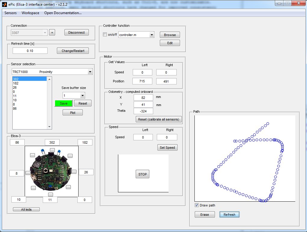
The ePic2 Matlab interface was adapted to work with the Elisa-3 robot. The communication is handled with the radio module. Both Matlab 32 bits and 64 bits are supported (tested on Matlab R2010a). Follow these steps to start playing with the interface:
- program the robot with the advanced demo
- place the selector in position 15 (to pilot the robot through the interface with no obstacle and no cliff avoidance)
- connect the radio base-station to the computer
- download the ePic2 for Elisa-3 from the repository https://github.com/gctronic/elisa3_epic.git: either from github site clicking on
Code=>Download ZIPor by issueing the commandgit clone https://github.com/gctronic/elisa3_epic.git - open (double click) the file main.m; once Matlab is ready type main+ENTER and the GUI should start
- click on the + sign (top left) and insert the robot address (e.g 3307), then click on Connect
Webots simulator
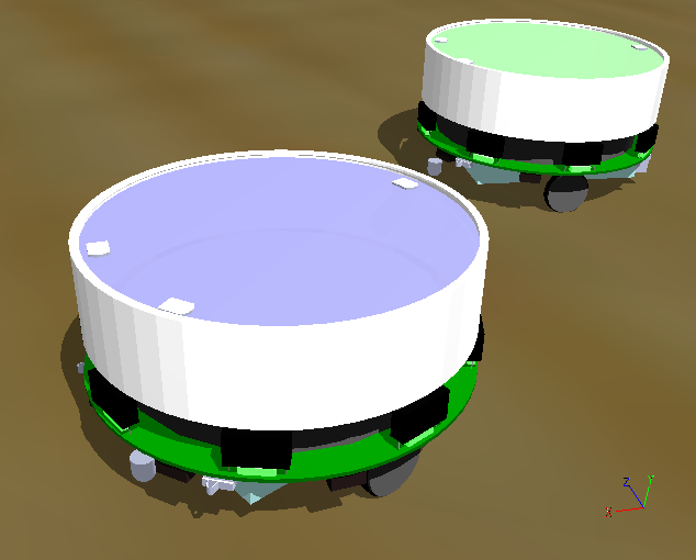
The following features have been included in the Elisa-3 model for the Webots simulator:
- proximity sensors
- ground sensors
- accelerometer
- motors
- green leds around the robot
- RGB led
- radio communication
You can donwload the Webots project containig the Elisa-3 model (proto) and a demonstration world in the following link Elisa-3-webots.zip.
You can download a Webots project containing a demonstration world illustrating the usage of the radio communication between 10 Elisa-3 robots and a supervisor in the following link Elisa-3-webots-radio.zip. Here is a video of this demo:
Onboard behaviors
The released firmware contains two basic onboard behaviors: obstacle and cliff avoidance. Both can be enabled and disabled from the computer through the radio (seventh bit of flags byte for obstacle avoidance, eight bit of flags byte for cliff avoidance).
The following videos show three robots that have their obstacle avoidance enabled:
Programming
The robot is pre-programmed with a serial bootloader. In order to upload a new program to the robot a micro USB cable is required. The connection with the robot is shown below:
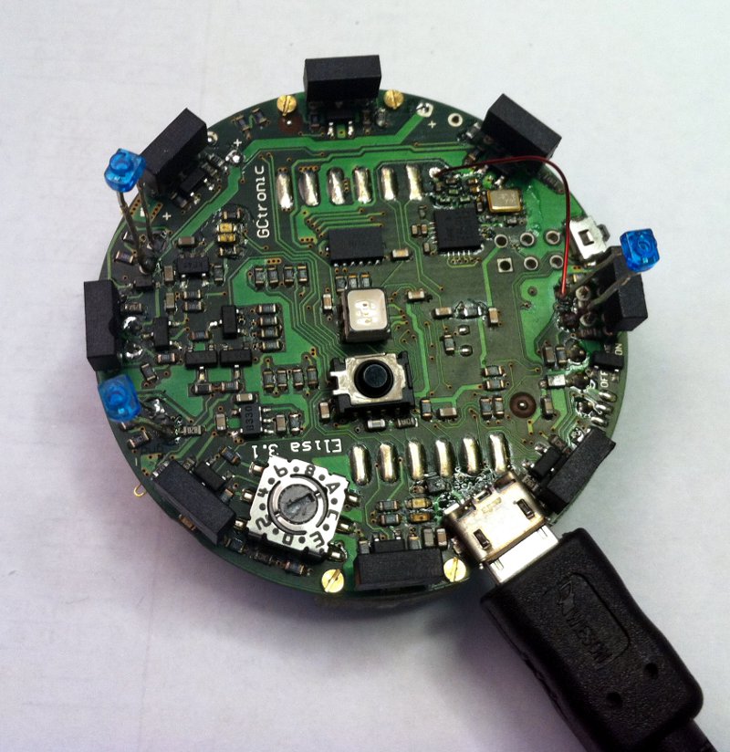
If you are working with the Arduino IDE you don't need to follow this procedure, refer instead to section Arduino IDE project.
If you encounter some problem during programming (e.g. timeout problems) you can try following this sequence: turn on the robot, unplug the robot from the computer, plug the robot into the computer, it will make some blinks; when the blinks terminate execute the programming command again.
Beware that every time you need to re-program the robot you need to unplug and plug again the cable to the computer.
Windows 7
- Download the Windows 7 package and extract it. The package contains also the FTDI driver.
- Execute the script
config.batand follow the installation; beware that this need to be done only once. The script will ask you to modify the registry, this is fine (used to save application preferences). - Connect the robot to the computer; the COM port will be created.
- Run the application
AVR Burn-O-Mat.exe; you need to configure the port to communicate with the robot:- click on
Settings => AVRDUDE - in the
AVRDUDE Options, onPortenter the name of the port just created when the robot was connected to the computer (e.g. COM10); then clickOk
- click on
- In the
Flashsection search the hex file you want to upload on the robot. - Turn on the robot, wait the blinks terminate and then click on
Writein theFlashsection. - During the programming the robot will blink; at the end you'll receive a message saying
Flash succesfully written.
Mac OS X
The following procedure is tested in Max OS X 10.10, but should work from Mac OS X 10.9 onwards; in these versions there is built-in support for the FTDI devices.
- Download the Mac OS X package and extract it.
- Execute the script
config.shin the terminal, it will ask you to install the Java Runtime Environment; in case there is a problem executing the script try withchmod +x config.shand try again. Beware that this need to be done only once. - Connect the robot to the computer; the serial device will be created (something like
/dev/tty.usbserial-AJ03296J). - Run the application
AVR Burn-O-Mat; you need to configure the port to communicate with the robot:- click on
Settings => AVRDUDE - in the
AVRDUDE Options, onPortenter the name of the port just created when the robot was connected to the computer; then clickOk
- click on
- In the
Flashsection search the hex file you want to upload on the robot. - Turn on the robot, wait the blinks terminate and then click on
Writein theFlashsection. - During the programming the robot will blink; at the end you'll receive a message saying
Flash succesfully written.
Linux
The following procedure was tested in Ubunut 12.04, but a similar procedure can be followed in newer systems and other Linux versions.
You can find a nice GUI for avrdude in the following link http://burn-o-mat.net/avr8_burn_o_mat_avrdude_gui_en.php; you can download directly the application for Ubuntu from the following link avr8-burn-o-mat-2.1.2-all.deb.
Double click the package and install it; the executable will be avr8-burn-o-mat.
Beware that the application requires the Java SE Runtime Environment (JRE) that you can download from the official page http://www.oracle.com/technetwork/java/javase/downloads/index.html, alternatively you can issue the command sudo apt-get install openjdk-8-jre in the terminal.
The application need a bit of configuration, follow these steps:
- 1. connect the robot to the computer, the serial device will be created (something like /dev/USB0)
- 2. to use the USB port the permissions need to be set to read and write issueing the command
sudo chmod a+rw /dev/ttyUSB0 - 3. start the application and click on
Settings => AVRDUDE - 4. set the location of
avrdudeand the related configuration file (refer to the previous section whenavrdudewas installed to know the exact location); the configuration file is in/etc/avrdude.conf - 3. click
OK, close the application and open it again (this is needed to load the configuration file information); click onSettings => AVRDUDE - 4. select
stk500v2as theProgrammer - 5. set the serial port connected to the robot (
/dev/ttyUSB0) - 6. in
additional optionsinsert-b 57600, you will end up with a window like the following one:
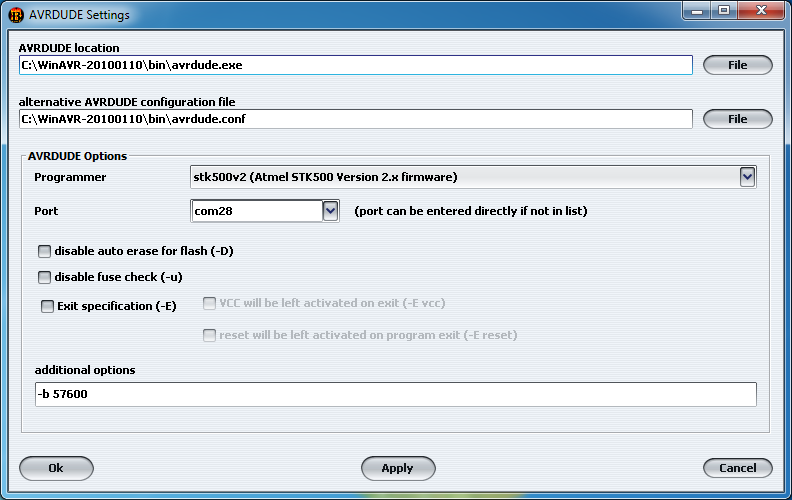
- 7. click
OK; selectATmega2560in theAVR type - 8. in the
Flashsection search the hex file you want to upload on the robot; selectIntel Hexon the right - 9. connect the robot to the computer, turn on the robot, wait the blinks terminate and then click on
Writein theFlashsection - 10. during the programming the robot will blink; at the end you'll receive a message saying
Flash succesfully written.
Command line
The avrdude utility is used to do the upload, you can download it directly from the following links depending on your system:
- Windows;
avrdudewill be installed in the pathC:\WinAVR-20100110\bin\avrdude; avrdude version 5.10 - Mac OS X;
avrdudewill be installed in the path/usr/local/CrossPack-AVR/bin/avrdude; to check the path issue the commmandwhich avrdudein the terminal; avrdude version 6.0.1 - Ubuntu (12.04 32-bit): issue the command
sudo apt-get install avrdudein the terminal;avrdudewill be installed in the path/usr/bin/avrdude; to check the path issue the commmandwhich avrdudein the terminal; avrdude version 5.11.1
Open a terminal and issue the command avrdude -p m2560 -P COM10 -b 57600 -c stk500v2 -D -Uflash:w:Elisa3-avr-studio.hex:i -v
where COM10 must be replaced with your com port and Elisa3-avr-studio.hex must be replaced with your application name; in Mac OS X the port will be something like /dev/tty.usbserial-..., in Ubuntu will be /dev/ttyUSB0.
The Basic demo and Advanced demo have this command contained in the file program.bat in the default directory within the project, this can be useful for Windows users.
Internal EEPROM
The internal 4 KB EEPROM that resides in the microcontroller is pre-programmed with the robot ID in the last two bytes (e.g. if ID=3200 (0x0C80), then address 4094=0x80 and address 4095=0x0C). The ID represents also the RF address that the robot uses to communicate with the computer and is automatically read at startup (have a look a the firmware for more details).
Moreover the address 4093 is used to save the clock calibration value that is found during production/testing of the robots; this value hasn't to be modified otherwise some functionalities such as tv remote control could not work anymore. For more information on clock calibration refers to the applicaiton note AVR053: Calibration of the internal RC oscillator.
The Elisa-3 robot supports an autonomous calibration process and the result of this calibration is saved in EEPROM starting at address 3946 to 4092.
The size of usable EEPROM is thus 3946 bytes (0-3945) and the remaining memory must not be modified/erased.
In order to program the eeprom an AVR programmer is required, we utilize the Pocket AVR Programmer from Sparkfun (recognized as USBtiny device); then with the avrdude utility the following command has to be issued:
avrdude -p m2560 -c usbtiny -v -U eeprom:w:Elisa3-eeprom.hex:i -v -B 1
where Elisa3-eeprom.hex is the EEPROM memory saved as Intel Hex format (eeprom example); a possible tool to read and write Intel Hex format is Galep32 from Conitec Datensysteme.
Alternatively a program designed to writing to these EEPROM locations can be uploaded to the robot, in case an AVR programmer isn't available. The project source is available in the repository https://github.com/gctronic/elisa3_eeprom.git; it is simply needed to modify the address, rebuild and upload to the robot.
Bootloader
In case the bootloader of the Elisa-3 is erased by mistake, then you can restore it by using an AVR programmer. You can download the bootloader from here stk500v2.hex; the source code is available from the repository https://github.com/gctronic/elisa3_bootloader.git.
Avrdude can be used to actually write the bootloader to the robot with a command similar to the following one:
avrdude -p m2560 -c stk500v2 -P COM348 -v -U lfuse:w:0xE2:m -U hfuse:w:0xD8:m -U efuse:w:0xFF:m -V -U flash:w:stk500v2.hex:i -v -B 2
Here we used a programmer recognized as a serial device (port COM348) that utilizes the stk500v2 protocol.
Base-station
This chapter explains informations that aren't needed for most of the users since the radio module is ready to be used and don't need to be reprogrammed. Only if you are interested in the firmware running in the radio module and on how to reprogram it then refer to section http://www.gctronic.com/doc/index.php/Elisa#Base-station (chapter 4.2) of the Elisa robot wiki.
PC side
This section gives informations related to the radio module connected to the computer; if you don't have a radio module you can skip this section.
Elisa-3 library
This library simplify the implementation of applications on the pc side (where the radio base-station is connected) that will take control of the robots and receive data from them. Some basic examples will be provided in the following sections to show how to use this library.
The source code of the library is available in the repository https://github.com/gctronic/elisa3_remote_library.
Multiplatform monitor
The demo is a command line monitor that shows all the sensors information (e.g. proximity, ground, acceleromter, battery, ...) and let the user move the robot and change its colors and behavior with the keyboard. The data are sent using the protocol described in the previous section.
The following figures show the monitor on the left and the available commands on the right.
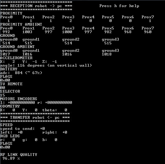
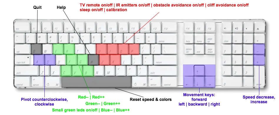
The source can be downloaded from the repository https://github.com/gctronic/elisa3_remote_monitor.
Windows
Execution:
- install the driver contained in the nRFgo Studio tool if not already done; this let the base-station be recognized as a WinUSB device (bootloader), independently of whether the libusb library is installed or not
- once the driver is installed, the pre-compiled "exe" (under
\bin\Releasedir) should run without problems; the program will prompt you the address of the robot you want to control
Compilation:
the Code::Blocks project should already be setup to reference the Elisa-3 library headers and lib files, anyway you need to put this project within the same directory of the Elisa-3 library, e.g. you should have a tree similar to the following one:
- Elisa-3 demo (parent dir)
elisa3_remote_library(Elisa-3 library project)elisa3_remote_monitor(current project)
Linux / Mac OS X
The project was tested to work also in Ubuntu and Mac OS X (no driver required).
Compilation:
- you need to put this project within the same directory of the Elisa-3 library
- build command: go under "linux" dir and type
make clean && make
Execution:
sudo ./main
Communicate with 4 robots simultaneously
This example shows how to interact with 4 robots simlutaneously, basically it shows the sensors information (proximity and ground) coming from 4 robots and let control one robot at a time through the keyboard (you can change the robot you want to control). The source can be downloaded from the repository https://github.com/gctronic/elisa3_remote_multiple. For building refer to the section Multiplatform monitor.
Obstacle avoidance
This demo implements the obstacle avoidance behavior controlling the robot from the pc through the radio; this means that the robot reacts only to the commands received using the basic communication protocol and has no "intelligence" onboard. The demo uses the information gathered from the 3 front proximity sensors and set the motors speed accordingly; moreover the RGB LED is updated with a random color at fixed intervals.
The source can be downloaded from the repository https://github.com/gctronic/elisa3_remote_oa. For building refer to the section Multiplatform monitor.
The following video shows the result:
It is available also the same example but with 4 robots controlled simultaneously; the source can be downloaded from the branch 4robots of the repository https://github.com/gctronic/elisa3_remote_oa
It is easy to extend the previous example in order to control many robots, the code that controls 8 robots simultaneously can be downloaded from the branch 8robots of the repository https://github.com/gctronic/elisa3_remote_oa.
Cliff avoidance
This demo implements the cliff avoidance behavior controlling the robot from the pc through the radio; as with the obstacle avoidance demo, the robot reacts only to the commands received from the radio. The demo uses the information gathered from the 4 ground sensors to stop the robot when a cliff is detected (threshold tuned to run in a white surface); moreover the RGB LED is updated with a random color at fixed intervals.
The source can be downloaded from the repository https://github.com/gctronic/elisa3_remote_cliff. For building refer to the section Multiplatform monitor.
The following video shows the result:
Set robots state from file
This project show how to send data to robots for which we will know the address only at runtime, in particular the content of the packets to be transmitted is parsed from a csv file and the interpreted commands are sent to the robots one time. The source can be downloaded from the repository https://github.com/gctronic/elisa3_remote_file. For building refer to the section Multiplatform monitor.
Odometry
The odometry of Elisa-3 is quite good even if the speed is only measured by back-emf. On vertical surfaces the absolute angle is given by the accelerometer measuring g... quite a fix reference without drifting ;-)
A fine calibration of the right and left wheel speed parameters might give better results.
However the current odometry is a good estimate of the absolute position from a starting point.
The experiments are performed on a square labyrinth and the robot advances doing obstacle avoidance. The on-board calculated (x,y,theta) position is sent to a PC via radio and logged for further display.
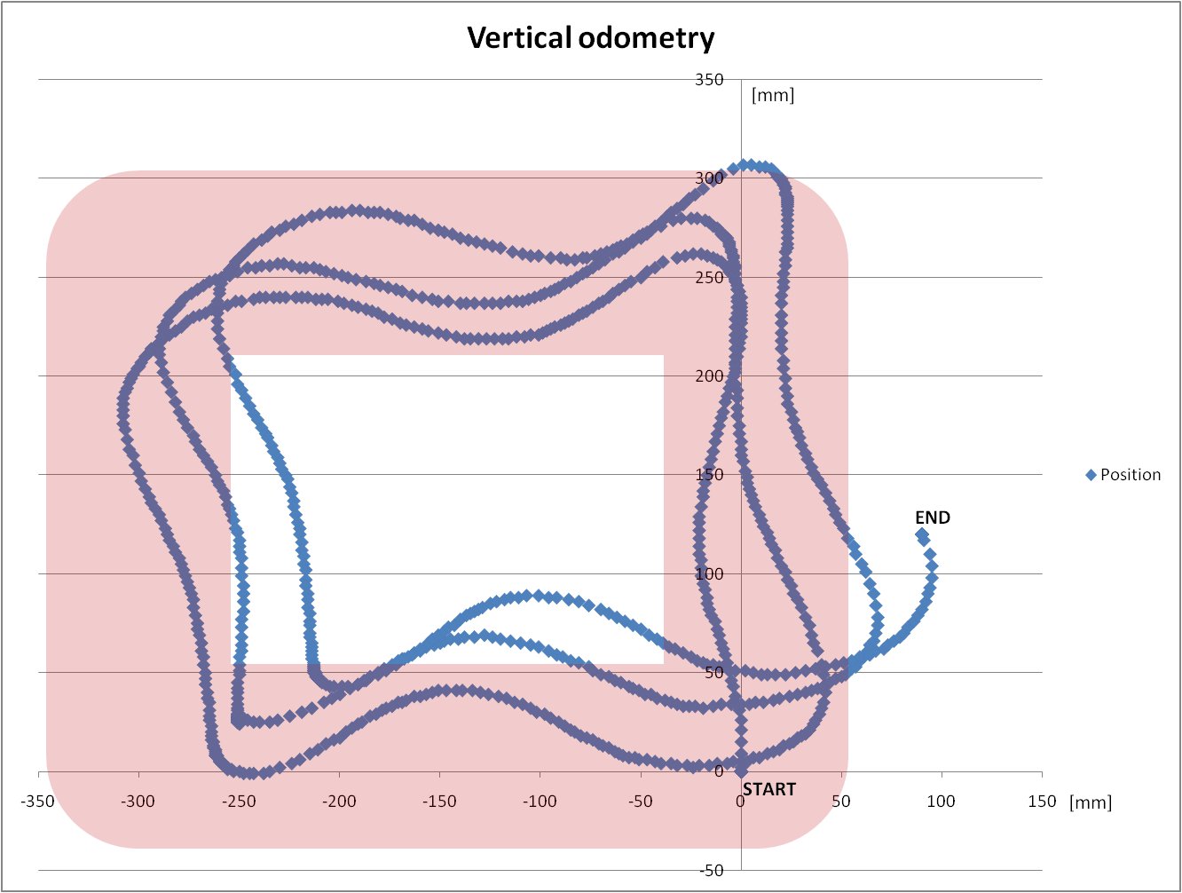
Details about the code can be found in the advanced-demo project, in particular the motors.c source file. The PC application used for logging data is the monitor.
Autonomous calibration
Since the motors can be slightly different a calibration can improve the behavior of the robot in terms of maneuverability and odometry accuracy.
An autonomous calibration process is implemented onboard: basically a calibration is performed for both the right and left wheels in two modes that are forward and backward with speed control enabled. In order to let the robot calibrate istelf a white sheet in which a black line is drawed is needed; the robot will measure the time between detection of the line at various speeds. The calibration sheet can be downloaded from the following link calibration-sheet.pdf.
In order to accomplish the calibration the robot need to be programmed with the advanced firmare and a specific command has to be sent to the robot through the radio module or the TV remote; if you are using the radio module you can use the monitor application in which the letter l (el) is reserved to launch the calibration, otherwise if you have a TV remote control you can press the button 5.
The sequence is the following:
1. put the selector in position 8
2. place the robot near the black line as shown below; the left motor is the first to be calibrated. Pay attention to place the right wheel as precise as possible with the black line
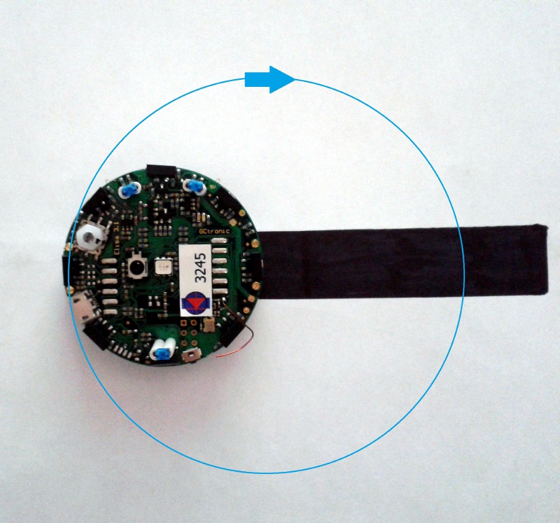
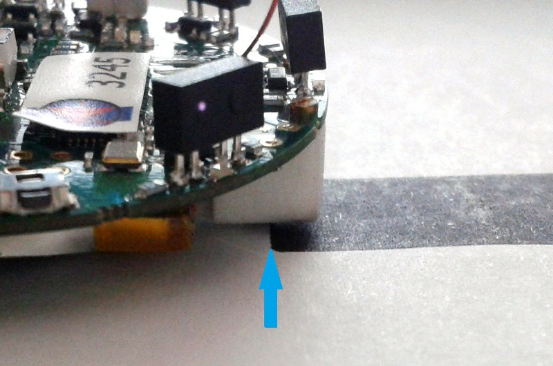
3. once the robot is placed you can type the l (el) command (or press the button 5); wait a couple of minutes during which the robot will do various turns at various speed in the forward direction and then in the backward direction
4. when the robot terminated (robot is stopped after going backward at high speed) you need to place it in the opposite direction in order to calibrate the right motor, as shown below.
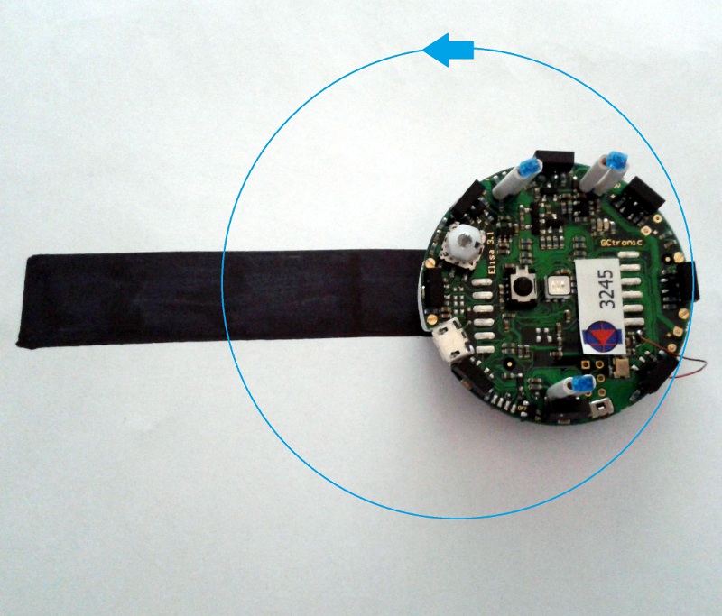
5. once the robot is placed you can type again the l (el) command (or press the button 5)
6. when the robot finish, the calibration process is also terminated.
The previous figures show a robot without the top diffuser, anyway you don't need to remove it!
Tracking
Assembly documentation
You can download the documentation from here tracking-doc.pdf.
Have a look also at the video:
SwisTrack
Some experiments are done with the SwisTrack software in order to be able to track the Elisa-3 robots through the back IR emitter, here is a resulting image with 2 robots:
![]()
The pre-compiled SwisTrack software (Windows) can be downloaded from the following link SwisTrack-compiled.
The following video shows the tracking of 5 robots:
The SwisTrack software lets you easily log also the resulting data that you can then elaborate, here is an example taken from the experiment using 5 robots:
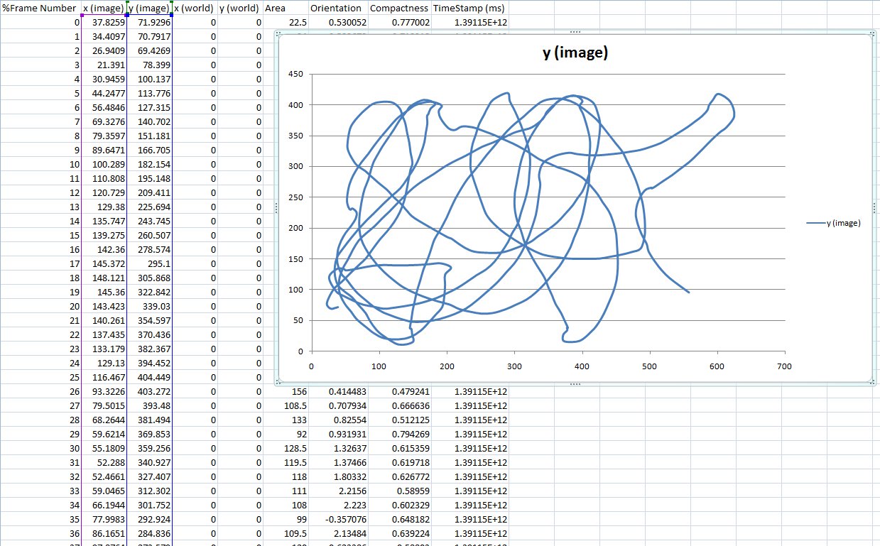
The following video shows the test done with 20, 30 and 38 Elisa-3 robots, the tracking is still good; it's important to notice that we stopped to 38 Elisa-3 robots because are the ones we have in our lab.
Position control
We developed a simple position control example that interacts with Swistrack through a TCP connection and control 4 robots simultaneously; the orientation of the robots is estimated only with the Swistrack information (delta position), future improvements will integrate odometry information. The following video shows the control of 4 robots that are driven in a 8-shape.
![]()
All the following projects require the Elisa-3 library, for building refer to the section Multiplatform monitor.
- Horizontal position control (4 robots): the source code can be downloaded from position-control-pattern-horizontal-4-robots.zip (Code::Blocks project).
One of the characteristics of the Elisa-3 robot is that it can move in vertical thanks to its magnetic wheels, thus we developed also a vertical position control that use accelerometer data coming from the robot to get the orientation of the robot (more precise) instead of estimating it with the Swistrack information, you can download the source code from the following link:
- Vertical position control (4 robots): position-control-pattern-vertical-4-robots.zip (Code::Blocks project).
We developed also an example of position control that control a single robot (code adapted from previous example) that can be useful during the initial environment installation/testing; you can download the source code from the following link:
- Horizontal position control (1 robot): position-control-pattern-horizontal-1-robot.zip (Code::Blocks project).
Another good example to start playing with the tracking is an application that lets you specify interactively the target point that the robot should reach; you can download the source code of this application from the following link:
- Go to target point: position-control-goto-pos-horizontal-1-robot.zip (Code::Blocks project).
Utilities
In order to adjust the IR camera position it is useful to have an application that turn on the back IR of the robots. The following application back-IR-on-4-robots-rev245-15.01.21.zip is an example that turn on the back IR of 4 robots, their addresses are asked to the user at the execution.
Local communication
The advanced firmware is needed in order to use the local communication. You can find some examples on how to use this module in the main, refers to demos in selector position from 11 to 14.
Here are some details about the current implementation of the communication module:
- use the infrared sensors to exchange data, thus during reception/transmission the proximity sensors cannot be used to avoid obstacles; in the worst case (continuous receive and transmit) the sensor update frequency is about 3 Hz
- bidirectional communication
- id and angle of the proximity sensor that received the data are available
- the throughput is about 1 bytes/sec
- maximum communication distance is about 5 cm
- no reception/transmission queue (only one byte at a time)
- the data are sent using all the sensors, cannot select a single sensor from which to send the data. The data isn't sent contemporaneously from all the sensors, but the sensors used are divided in two groups of 4 alternating sensors (to reduce consumption)
ROS
This chapter explains how to use ROS with the elisa-3 robots; the radio module is needed here. Basically all the sensors are exposed to ROS and you can also send commands back to the robot through ROS. The ROS node is implemented in cpp. Here is a general schema:
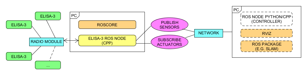 Click to enlarge
First of all you need to install and configure ROS, refer to http://wiki.ros.org/Distributions for more informations. Alternatively you can download directly a virtual machine pre-installed with everything you need, refer to section virtual machine; this is the preferred way.
- This tutorial is based on ROS Hydro. The same instructions are working with ROS Noetic, beware to use
noeticinstead ofhydrowhen installing the packages. - If you downloaded the pre-installed VM you can go directly to section Running the ROS node.
- This tutorial is based on ROS Hydro. The same instructions are working with ROS Noetic, beware to use
The ROS elisa-3 node based on roscpp can be found in the following repository https://github.com/gctronic/elisa3_node_cpp.
Initial configuration
The following steps need to be done only once after installing ROS:
- 1. If not already done, create a catkin workspace, refer to http://wiki.ros.org/catkin/Tutorials/create_a_workspace. Basically you need to issue the following commands:
  mkdir -p ~/catkin_ws/src
  cd ~/catkin_ws/src
  catkin_init_workspace
  cd ~/catkin_ws/
  catkin_make
  source devel/setup.bash
- 2. You will need to add the line
source ~/catkin_ws/devel/setup.bashto your .bashrc in order to automatically have access to the ROS commands when the system is started - 3. Clone the elisa-3 ROS node repo from https://github.com/gctronic/elisa3_node_cpp inside the catkin workspace source folder (~/catkin_ws/src):
git clone https://github.com/gctronic/elisa3_node_cpp.git - 4. Install the dependencies:
- ROS:
sudo apt-get install ros-hydro-slam-gmappingsudo apt-get install ros-hydro-imu-tools
- If you are using a newer version of ROS, replace
hydrowith your distribution name.
- cpp:
- install OpenCV:
sudo apt-get install libopencv-dev
- install OpenCV:
- If you are working with OpenCV 4, then you need to change the header include from
#include <opencv/cv.h>to#include <opencv2/opencv.hpp>
- 5. Rebuild the
elisa-3 library: go to~/catkin_ws/src/elisa3_node_cpp/src/pc-side-elisa3-library/linux, then issuemake cleanandmake - 6. Open a terminal and go to the catkin workspace directory (~/catkin_ws) and issue the command
catkin_make, there shouldn't be errors - 7. The USB radio module by default requires root priviliges to be accessed; to let the current user have access to the radio we use udev rules:
- in the udev rules file you can find in /etc/udev/rules.d/name.rules add the following string changing the GROUP field with your current user group:
- SUBSYSTEMS=="usb", ATTRS{product}=="nRF24LU1P-F32 BOOT LDR", GROUP="viki"
- To know which groups your user belongs to issue the command id
- disconnect and reconnect the radio module
- 8. Program the elisa-3 robot with the last advanced firmware (>= rev.221) and put the selector in position 15
Running the ROS node
First of all get the last version of the elisa-3 ROS node from github:
- clone the repo https://github.com/gctronic/elisa3_node_cpp and copy the elisa3_node_cpp directory inside the catkin workspace source folder (e.g. ~/catkin_ws/src)
- build the driver by opening a terminal and issueing the command
catkin_makefrom within the catkin workspace directory (e.g. ~/catkin_ws).
Now you can start the ROS node, for this purposes there is a launch script (based on roslaunch), as explained in the following section. Before starting the ROS node you need to start roscore, open another terminal tab and issue the command roscore.
Single robot
Open a terminal and issue the following command: roslaunch elisa3_node_cpp elisa3_single.launch elisa3_address:='1234' where 1234 is the robot id (number on the bottom).
If all is going well rviz will be opened showing the informations gathered from the topics published by the elisa ROS node as shown in the following figure:
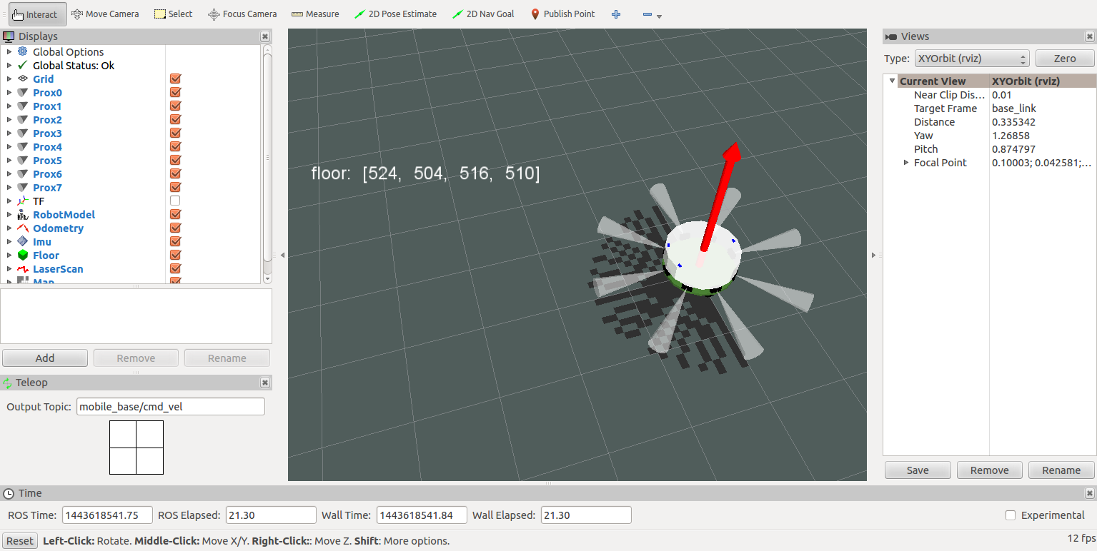 Click to enlarge
The launch script is configured also to run the gmapping (SLAM) node that let the robot construct a map of the environment; the map is visualized in real-time directly in the rviz window. Here is a video:
Troubleshooting
Robot state publisher
If you get an error similar to the following when you start a node with roslaunch:
ERROR: cannot launch node of type [robot_state_publisher/state_publisher]: Cannot locate node of type [state_publisher] in package [robot_state_publisher]. Make sure file exists in package path and permission is set to executable (chmod +x)
Then you need to change the launch file from:
<node name="elisa3_state_publisher" pkg="robot_state_publisher" type="state_publisher" />
To:
<node name="elisa3_state_publisher" pkg="robot_state_publisher" type="robot_state_publisher" />
This is due to the fact that state_publisher was a deprecated alias for the node named robot_state_publisher (see https://github.com/ros/robot_state_publisher/pull/87).
Virtual machine
To avoid the tedious work of installing and configuring all the system we provide a virtual machine which includes all the system requirements you need to start playing with ROS and elisa. You can download the image as open virtualization format from the following link ROS-Hydro-12.04.ova (based on the VM from http://nootrix.com/2014/04/virtualized-ros-hydro/); you can then use VirtualBox to import the file and automatically create the virtual machine. Some details about the system:
- user: gctronic, pw: gctronic
- Ubuntu 12.04.4 LTS (32 bits)
- ROS Hydro installed
- Webots 8.0.5 is installed (last version available for 32 bits linux)
- git-cola (git interface) is installed
- the catkin workspace is placed in the desktop
Videos
Autonomous charge
The following videos show 3 Elisa-3 robots moving around in the environment avoiding obstacles thanks to their proximity sensors and then going to the charging station autonomously; some black tape is placed in the charging positions to help the robots place themselves thanks to their ground sensors. The movement and charging is indipendent of the gravity. It works also vertically and up-side-down.
Remote control
The following video shows 38 Elisa-3 robots moving around with onboard obstacle avoidance enabled; 15 of them are running autonmously, the remaining 23 are controlled from one computer with the radio module.