Ring and Ultra Wide Band Extension: Difference between pages
No edit summary |
No edit summary |
||
| Line 1: | Line 1: | ||
= | =Development= | ||
The following figure shows the architecture details during the development phase:<br/> | |||
<span class="plainlinks">[https://projects.gctronic.com/elisa3/uwb/architecture-development.jpg <img width=600 src="https://projects.gctronic.com/elisa3/uwb/architecture-development.jpg">]</span><br/> | |||
On the nRF52832 the firmware is developed using the C API based on the PANS stack released by Decawave. The communication with the Elisa-3 robot is accomplished through I2C (the robot is the slave). The nRF52 is programmed/debugged through the SWD interface using an external nRF dev kit attached to the computer via USB. An additional UART is attached to the UWB module in order to get logging info. | |||
[ | ==Cabling== | ||
Power taken from the regulated 3V3 digital of Elisa.<br/> | |||
[ | On Elisa need to be added 2 simple female connectors, 2 and 3 pins. Painted in white on one side to help not crossing the cabling.<br/> | ||
<span class="plainlinks">[https://projects.gctronic.com/elisa3/uwb/DWM1001cabling_1.jpg <img width=600 src="https://projects.gctronic.com/elisa3/uwb/DWM1001cabling_1.jpg">]</span><br/> | |||
<span class="plainlinks">[https://projects.gctronic.com/elisa3/uwb/ElisaUWB_1.jpg <img width=600 src="https://projects.gctronic.com/elisa3/uwb/ElisaUWB_1.jpg">]</span><br/> | |||
<span class="plainlinks">[https://projects.gctronic.com/elisa3/uwb/ElisaUWB_2.jpg <img width=600 src="https://projects.gctronic.com/elisa3/uwb/ElisaUWB_2.jpg">]</span><br/> | |||
<span class="plainlinks">[https://projects.gctronic.com/elisa3/uwb/ElisaUWBdebugger.jpg <img width=300 src="https://projects.gctronic.com/elisa3/uwb/ElisaUWBdebugger.jpg">]</span> | |||
<span class="plainlinks">[https://projects.gctronic.com/elisa3/uwb/ElisaUwbDevkitUart.jpg <img width=300 src="https://projects.gctronic.com/elisa3/uwb/ElisaUwbDevkitUart.jpg">]</span><br/> | |||
=I2C protocol= | |||
The nRF52 (master) writes all the actuators at once and read all the sensors data at once.<br/> | |||
<span class="plainlinks">[https://projects.gctronic.com/elisa3/uwb/protocol-elisa-to-nrf52.jpg <img width=900 src="https://projects.gctronic.com/elisa3/uwb/protocol-elisa-to-nrf52.jpg">]</span><br/> | |||
<span class="plainlinks">[https://projects.gctronic.com/elisa3/uwb/protocol-nrf52-to-elisa.jpg <img width=600 src="https://projects.gctronic.com/elisa3/uwb/protocol-nrf52-to-elisa.jpg">]</span><br/> | |||
=Implementation= | |||
At the moment there are two firmwares for nRF52: one configures the module as a TAG node and the other one as an ANCHOR node. | |||
Once the two modules are programmed, the [https://projects.gctronic.com/elisa3/uwb/DRTLS_Manager_R2.apk Android application] is used to put the two nodes in the same network. | |||
Once configured, the TAG node will receive distances information and reflects the distance to the RGB led (intensity proportional to distance) while printing also this information to the UART.<br/> | |||
The nRF52 poll the Elisa-3 robot at about 20 Hz in a separate thread. | |||
<span class="plainlinks">[https://projects.gctronic.com/elisa3/uwb/architecture-implementation.jpg <img width=600 src="https://projects.gctronic.com/elisa3/uwb/architecture-implementation.jpg">]</span><br/> | |||
=Source code= | |||
Both the examples (<code>dwm-simple-anchor</code> and <code>dwm-simple-tag</code>) are based on the <code>dwm-simple</code> example that can be found in the [https://www.decawave.com/wp-content/uploads/2019/03/DWM1001_DWM1001-DEV_MDEK1001_Sources_and_Docs_v9.zip Decawave source code package]. | |||
To build the examples, clone the repo ([https://github.com/gctronic/dwm1001_anchor https://github.com/gctronic/dwm1001_anchor] and [https://github.com/gctronic/dwm1001_tag https://github.com/gctronic/dwm1001_tag]) inside the <code>DWM1001_DWM1001-DEV_MDEK1001_Sources_and_Docs_v9\DWM1001\Source_Code\DWM1001_on_board_package\dwm\examples</code> directory. Then use the [https://www.segger.com/downloads/embedded-studio Segger Embedded Studio for ARM] to build the project. | |||
The Elisa-3 firmware can be cloned from the repo [https://github.com/gctronic/elisa3_firmware_advanced https://github.com/gctronic/elisa3_firmware_advanced], <code>uwb</code> branch. The project can be built with [https://microchipdeveloper.com/atstudio:start Atmel Studio]. The selector must placed in position 15. | |||
=DFU= | |||
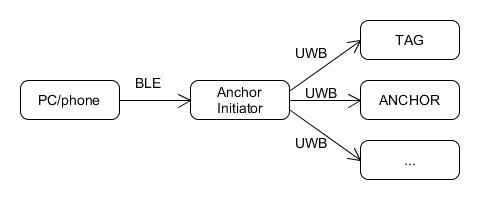
There is the possibility to update the firmware of the nodes via OTA (Over The Air).<br/> | |||
First the initiator anchor is updated via BLE, then this anchor will automatically update the remaining network nodes via UWB.<br/> | |||
<span class="plainlinks">[https://projects.gctronic.com/elisa3/uwb/architecture-dfu.jpg <img width=600 src="https://projects.gctronic.com/elisa3/uwb/architecture-dfu.jpg">]</span><br/> | |||
For more information refer to <code>DWM1001 Firmware API Guide</code>, chapter 4.3.<br/> | |||
<b>Not tested yet</b>. | |||
=Documentation= | |||
# [https://projects.gctronic.com/elisa3/uwb/DWM1001_Datasheet.pdf DWM1001_Datasheet.pdf] | |||
# [https://projects.gctronic.com/elisa3/uwb/DWM1001_Firmware_User_Guide.pdf DWM1001_Firmware_User_Guide.pdf] | |||
# [https://projects.gctronic.com/elisa3/uwb/DWM1001_Firmware_API_Guide.pdf DWM1001_Firmware_API_Guide.pdf] | |||
# [https://projects.gctronic.com/elisa3/uwb/DWM1001_Gateway_Quick_Deployment_Guide.pdf DWM1001_Gateway_Quick_Deployment_Guide.pdf] | |||
# [https://projects.gctronic.com/elisa3/uwb/System_Overview_and_Performance_for_DWM1001.pdf System_Overview_and_Performance_for_DWM1001.pdf] | |||
Latest revision as of 07:54, 29 September 2021
Development
The following figure shows the architecture details during the development phase:
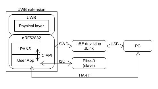
On the nRF52832 the firmware is developed using the C API based on the PANS stack released by Decawave. The communication with the Elisa-3 robot is accomplished through I2C (the robot is the slave). The nRF52 is programmed/debugged through the SWD interface using an external nRF dev kit attached to the computer via USB. An additional UART is attached to the UWB module in order to get logging info.
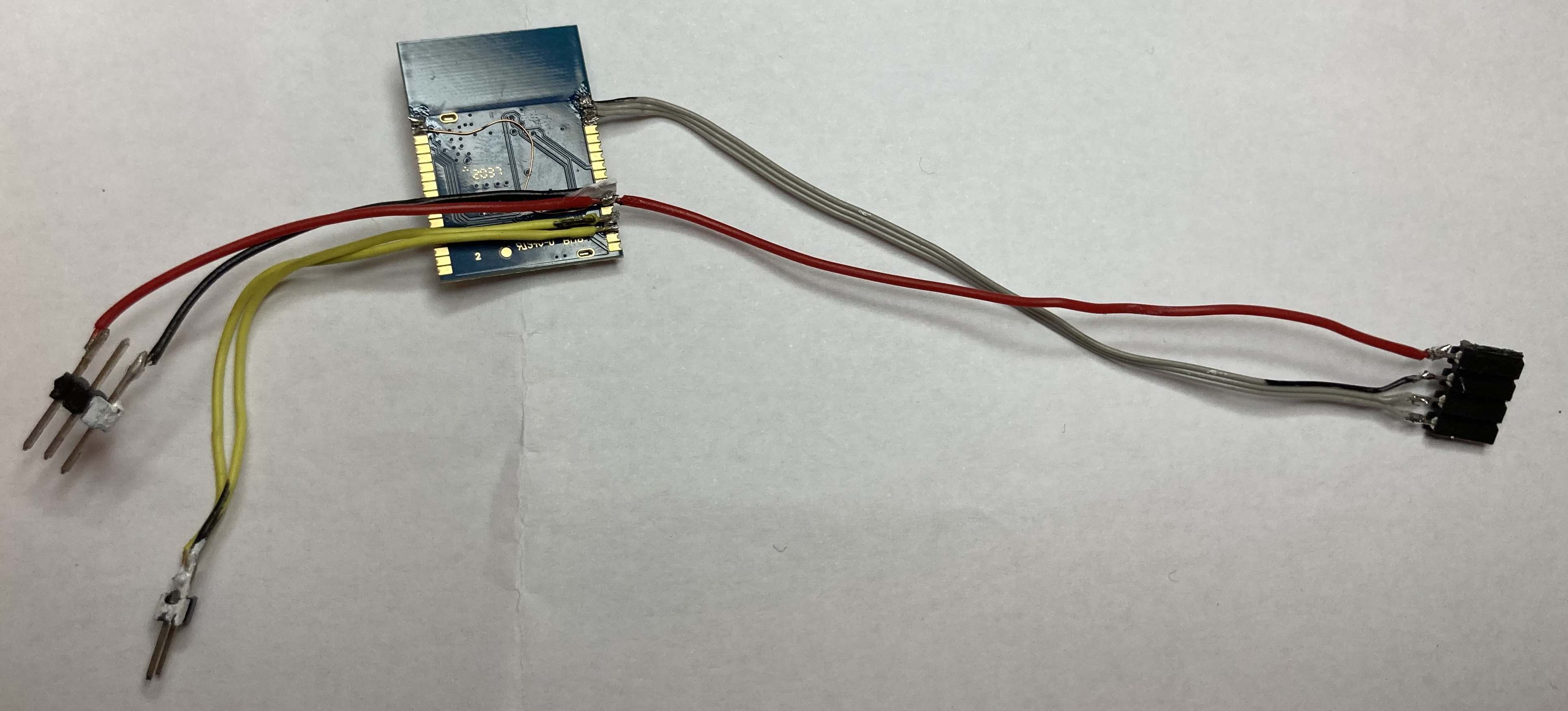
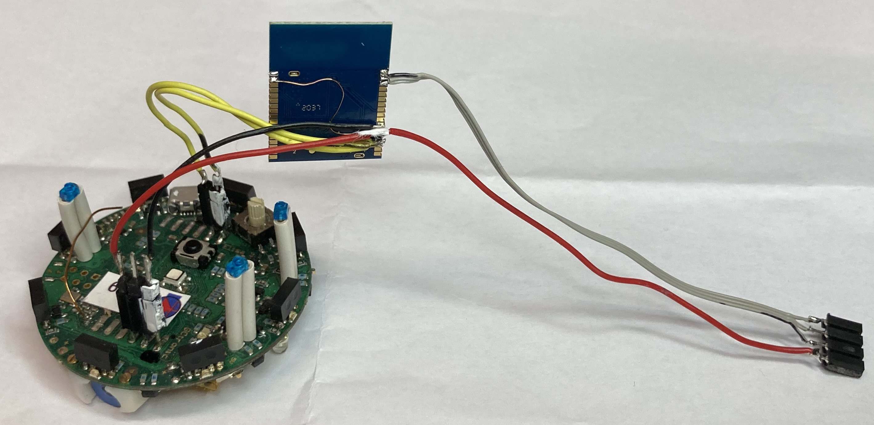
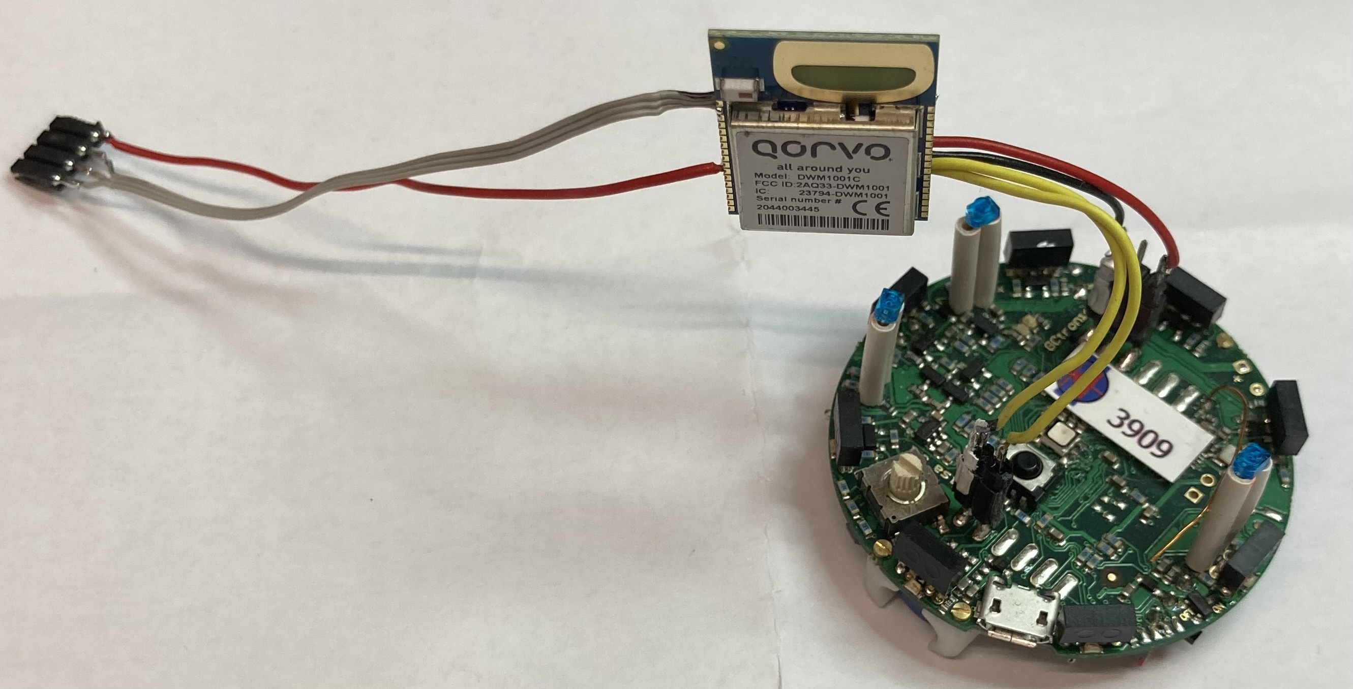
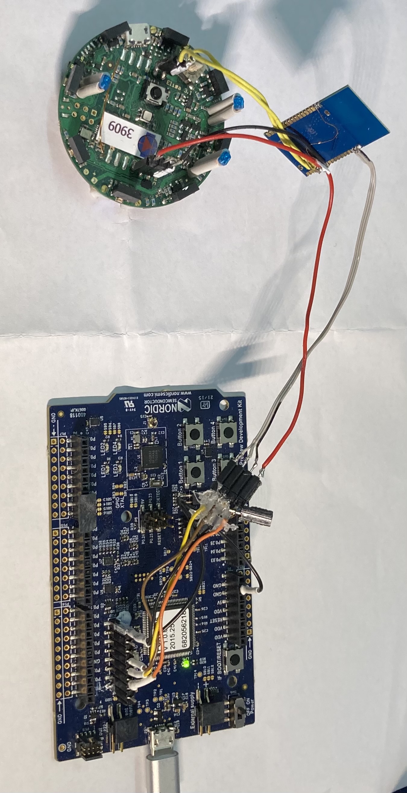
Cabling
Power taken from the regulated 3V3 digital of Elisa.
On Elisa need to be added 2 simple female connectors, 2 and 3 pins. Painted in white on one side to help not crossing the cabling.

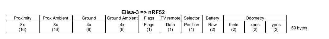
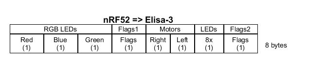
I2C protocol
The nRF52 (master) writes all the actuators at once and read all the sensors data at once.
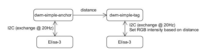
Implementation
At the moment there are two firmwares for nRF52: one configures the module as a TAG node and the other one as an ANCHOR node.
Once the two modules are programmed, the Android application is used to put the two nodes in the same network.
Once configured, the TAG node will receive distances information and reflects the distance to the RGB led (intensity proportional to distance) while printing also this information to the UART.
The nRF52 poll the Elisa-3 robot at about 20 Hz in a separate thread.
Source code
Both the examples (dwm-simple-anchor and dwm-simple-tag) are based on the dwm-simple example that can be found in the Decawave source code package.
To build the examples, clone the repo (https://github.com/gctronic/dwm1001_anchor and https://github.com/gctronic/dwm1001_tag) inside the DWM1001_DWM1001-DEV_MDEK1001_Sources_and_Docs_v9\DWM1001\Source_Code\DWM1001_on_board_package\dwm\examples directory. Then use the Segger Embedded Studio for ARM to build the project.
The Elisa-3 firmware can be cloned from the repo https://github.com/gctronic/elisa3_firmware_advanced, uwb branch. The project can be built with Atmel Studio. The selector must placed in position 15.
DFU
There is the possibility to update the firmware of the nodes via OTA (Over The Air).
First the initiator anchor is updated via BLE, then this anchor will automatically update the remaining network nodes via UWB.
For more information refer to DWM1001 Firmware API Guide, chapter 4.3.
Not tested yet.