|
|
| Line 1: |
Line 1: |
| =Overview=
| |
| The RGB panel is a new module designed to be suitable for the e-puck robot. It is comprised of:
| |
| * 9 RGB LEDs
| |
| * 8 infrareds
| |
| * [http://www.microchip.com/wwwproducts/Devices.aspx?dDocName=en010316 PIC18F6722 microcontroller] ([http://ww1.microchip.com/downloads/en/DeviceDoc/39646c.pdf datasheet])
| |
| Every LED is independent from each other, so it's possible to turn on the LEDs with different colors in the RGB color space (additive color mixing), as shown in the following figures.<br/>
| |
| <span class="plainlinks">[http://www.gctronic.com/doc/images/RGBpanel1.png <img height=200 src="http://www.gctronic.com/doc/images/RGBpanel1.png">]</span>
| |
| <span class="plainlinks">[http://www.gctronic.com/doc/images/RGBpanel2.png <img height=200 src="http://www.gctronic.com/doc/images/RGBpanel2.png">]</span>
| |
| <span class="plainlinks">[http://www.gctronic.com/doc/images/Rgb-panel1.jpg <img height=200 src="http://www.gctronic.com/doc/images/Rgb-panel1.jpg">]</span>
| |
| <span class="plainlinks">[http://www.gctronic.com/doc/images/Rgb-panel2.jpg <img height=200 src="http://www.gctronic.com/doc/images/Rgb-panel2.jpg">]</span>
| |
|
| |
| The infrareds are thought as identification sensors, this means that the robots can be recognized by an external device such as a camera observing their combination of infrareds turned on and off; for instance using 8 IRs it's possible to identify 256 different robots.
| |
|
| |
| The communication between the e-puck and the module is via the I2C bus. Color commands are sent from the robot to the RGB panel (nothing is sent in the opposite way); this let us, for example, program the robot with a pre-fixed sequence of commands to send to the panel, resulting in a color animation. Other more elaborate demos could be implemented, reacting for example to the environment and nearby robots.<br/>
| |
| Another possibility is to develop a demo running on a computer and connecting the computer to the e-puck through Bluetooth (the e-puck and the module are connected through I2C as before); in practice the robot receives commands from the PC and forwards them to the RGB panel. This forwarding is implemented in the e-puck firmware, presented afterwards.
| |
|
| |
| =Electrical schema=
| |
| The circuit diagram of the rgb panel e-puck extension is available to the community on the following link [https://projects.gctronic.com/rgb-panel/rgb-ext-electrical-schema.pdf electrical schema].
| |
|
| |
| =Software= | | =Software= |
| ==E-puck firmware==
| | * [https://projects.gctronic.com/bracelet/antusb-gethistory-rev350-15.04.13.zip get history] (to be used with ant usb stick); just start the executable named ''antusb-gethistory.exe'' and follows the instructions; the transfer lasts about 90 seconds and produces a csv file ''history.csv''; the zip file contains also the driver needed to install the ant usb stick in Windows (look for ''ANT_USB_Stick_2.inf''). |
| In order to play with the RGB extension for the e-puck robot you need to load the official e-puck firmware and set the selector on position 3 (advanced sercom protocol), refer to section [http://www.gctronic.com/doc/index.php/E-Puck#Standard_firmware E-Puck Standard firmware]. Basically the firmware contains a command to setup the color of each led and the state of each infrared sensor; in particular there are two commands (binary mode): 'W' and 'w'; the first one is used to set a single led or infrared sensor, the second is used to set all actuators at once.
| | ** [https://projects.gctronic.com/bracelet/History-format.doc history format]; beware that the current firmware version of the ring save also the data related to the accelerometer, this means that when two hearth rate values are saved in memory, also two values for the movement representation and two values for the energy representation are saved; thus in total 6 values in this sequence: ''HR HR MOVEMENT MOVEMENT ENERGY ENERGY'' |
| | | ** the file ''history.xls'' can be used to parse the history |
| ==RGB panel firmware==
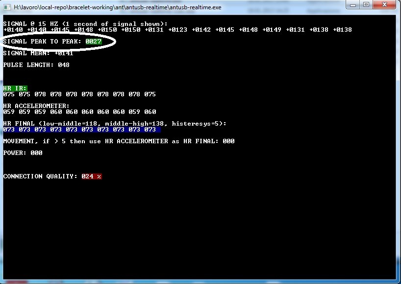
| | * [https://projects.gctronic.com/bracelet/antusb-realtime-rev355-13.06.13.zip get realtime data] (to be used with ant usb stick); just start the exceutable ''antusb-realtime.exe'' and follows the instructions. The file saves the data every about 60 millisecond into the file ''data.csv''. |
| Also the module requires a firmware running on it in order to handle the I2C communication and interpret the commands needed to turn on and off the sensors and color leds. The firmware can be downloaded from the following links ([https://projects.gctronic.com/rgb-panel/panel-firmware.zip panel-MPLAB], [https://projects.gctronic.com/rgb-panel/panel-firmware.hex panel-hex]).
| | The ''peak to peak'' indicates whether the signal is good enough for the algorithm, the following image shows an example of a good signal (green):<br/> |
| | | [http://www.gctronic.com/doc/images/antusb-realtime-good.jpg <img size=250>http://www.gctronic.com/doc/images/antusb-realtime-good.jpg</img>] <br/> |
| ==Demo - PC side==
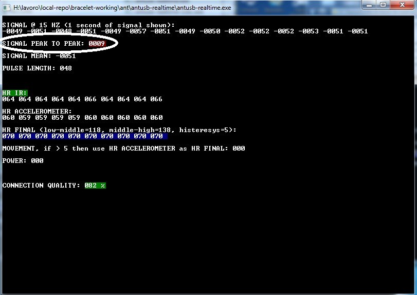
| | The following image instead shows a bad signal (red):<br/> |
| A basic demo running on a computer was developed to control manually all the LEDs color and IRs state through a Bluetooth connection. The application is implemented with [https://www.qt.io/download Qt]. A snapshot of this demo is shown hereafter:<br/>
| | [http://www.gctronic.com/doc/images/antusb-realtime-bad.jpg <img size=250>http://www.gctronic.com/doc/images/antusb-realtime-bad.jpg</img>] |
| <span class="plainlinks">[http://www.gctronic.com/doc/images/LEDTurretDemo.png <img width=400 src="http://www.gctronic.com/doc/images/LEDTurretDemo.png">]</span>
| |
| | |
| [http://www.gctronic.com/doc/images/LEDsTurret1.7.zip Download RGB Panel Basic Demo (Multiplatform)], built with Qt-5.10.1. | |
| | |
| ==e-puck2==
| |
| To play with the e-puck2 robot and RGB extension you can run the same [https://www.gctronic.com/doc/index.php?title=RGB_Panel#Demo_-_PC_side PC side application] that is used with the e-puck1. In this case the e-puck2 robot must be programmed with the [https://www.gctronic.com/doc/index.php?title=e-puck2#Factory_firmware factory firmware] and the selector must be placed in position 3.
| |
| | |
| Beware that in order to change the selector postion, <b>both the e-puck2 and RGB panel must have the selector in the same position</b>, this means that if you want the position 3 selected, then both the selector of the robot and the selector of the RGB panel must be placed in position 3.
| |
| | |
| If you want to control the RGB extension directly from the e-puck2, then you can do it by using the I2C bus (see chapter [https://www.gctronic.com/doc/index.php?title=RGB_Panel#Registers Registers]). An example is provided to help you getting started, have a look at the following repository [https://github.com/e-puck2/e-puck2_rgb_panel https://github.com/e-puck2/e-puck2_rgb_panel].
| |
| | |
| =Programming=
| |
| ==Registers==
| |
| The LEDs and IRs are controlled by writing appropriate registers; the value within the registers represents the duty cycle that a LED/IR will reach, that is its brightness. The following table shows the registers used to configure the various LEDs and IRs.
| |
| <blockquote>
| |
| {| border="1" cellpadding="10" cellspacing="0"
| |
| !X !! RedX !! BlueX !! GreenX !! IRX
| |
| |+ align="bottom" style="color:#e76700;" |''Parameter registers''
| |
| |-
| |
| |0 || 0x00 || 0x08 || 0x10 || 0xA4
| |
| |-
| |
| |1 || 0x01 || 0x09 || 0x11 || 0xA5
| |
| |-
| |
| |2 || 0x02 || 0x0A || 0x12 || 0xA6
| |
| |-
| |
| |3 || 0x03 || 0x0B || 0x13 || 0xA7
| |
| |-
| |
| |4 || 0x04 || 0x0C || 0x14 || 0xA8
| |
| |-
| |
| |5 || 0x05 || 0x0D || 0x15 || 0xA9
| |
| |-
| |
| |6 || 0x06 || 0x0E || 0x16 || 0xAA
| |
| |-
| |
| |7 || 0x07 || 0x0F || 0x17 || 0xAB
| |
| |-
| |
| |8 || 0x92 || 0x93 || 0x94 || -
| |
| |}
| |
| </blockquote> | |
| | |
| ==Example==
| |
| | |
| The RGB panel can be controlled through either ASCII or binary commands. The following example illustrates the sequence of commands that must be
| |
| issued to turn on the LED0 at maximum brightness (all 3 R,G and B at maximum) using a terminal and the e-puck programmed with the standard firmware: <br/>
| |
| <pre>
| |
| W, 176, 0, 128 [set red led0 max]
| |
| W, 176, 8, 128 [set blue led0 max ]
| |
| W, 176, 16, 128 [set green led0 max]
| |
| W, 176, 145, 1 [set command register (command terminator)]
| |
| </pre>
| |
| where in the first line ''W'' is the command (I2C write), ''176'' is the I2C address of the RGB panel (fixed), ''0'' is the register address and ''128'' the brightness value. The last line contains a special command that is sent to the module when it's required to update the LEDs and IRs with the new values; this means that even if the first command is sent to the RGB panel, nothing will change until the last command is sent.
| |
| | |
| The binary version (a bit faster), using the ''-w'' command, of the previous sequence is:
| |
| <pre>
| |
| ... init communication ...
| |
| | |
| sprintf(buffer, 5, "%c%c%c%c",-‘w’, 176, 0, 128);
| |
| sprintf(&buffer[5], 5, "%c%c%c%c",-‘w’, 176, 8, 128);
| |
| sprintf(&buffer[10], 5, "%c%c%c%c",-‘w’, 176, 16, 128);
| |
| sprintf(&buffer[15], 5, "%c%c%c%c",-‘w’, 176, 145, 1);
| |
| | |
| ... send buffer ...
| |
| </pre>
| |
| | |
| =Videos=
| |
| {{#ev:youtube|7S3qxfLEKTg}}
| |
| | |
| The robot changes color basing itself on what his small camera sees, just like a real chameloen. This system is based on the standard e-puck on the bottom, the new 3x3 RGB display on top and a proper demo.<br/>
| |
| You can download the source code of this demo in the following link [https://projects.gctronic.com/rgb-panel/epuck-demo4.zip epuck-demo-chamaleon].
| |
| | |
| {{#ev:youtube|pJVS-9sMiVY}}
| |
| | |
| Artistic pattern formation with multiple robots.
| |