E-Puck: Difference between revisions
(Created page with "<!--<div style="float:right;">__TOC__</div>--> =Hardware= ==Revisions== There are three hardware revisions: * HWRev 1.1: models from 0 to 1499 * HWRev 1.2: models from 1500...") |
(→Links) |
||
| Line 634: | Line 634: | ||
=Links= | =Links= | ||
[http://www.e-puck.org/ http://www.e-puck.org/] <br/> | [http://www.e-puck.org/ http://www.e-puck.org/] <br/> | ||
[ | [https://www.cyberbotics.com/doc/guide/epuck https://www.cyberbotics.com/doc/guide/epuck] <br/> | ||
[http://mobots.epfl.ch/e-puck.html http://mobots.epfl.ch/e-puck.html] <br/> | [http://mobots.epfl.ch/e-puck.html http://mobots.epfl.ch/e-puck.html] <br/> | ||
[https://github.com/gctronic/e-puck-library https://github.com/gctronic/e-puck-library] <br/> | [https://github.com/gctronic/e-puck-library https://github.com/gctronic/e-puck-library] <br/> | ||
Revision as of 10:59, 24 May 2018
Hardware
Revisions
There are three hardware revisions:
- HWRev 1.1: models from 0 to 1499
- HWRev 1.2: models from 1500 on, production of June 2008
- HWRev 1.3: models from 3320 on, production August 2014
The following table summarizes the differences between revisions:
| Camera | Bluetooth | Accelerometer | Microphone | |
|---|---|---|---|---|
| HWRev 1.1 | PixelPlus PO3030 (VGA) | LMX9820 Bluetooth 1.1 | MMA7260 3-axes analog acclerometer | SiSonic SP0103NC3-3 |
| HWRev 1.2 | PixelPlus PO6030 (VGA) | LMX9838 Bluetooth 2.0 | MMA7260 3-axes analog acclerometer | SiSonic SPM0208HD5 |
| HWRev 1.3 | PixelPlus PO8030 (VGA) | LMX9838 Bluetooth 2.0 | LSM330 3-axes digital (I2C) acclerometer + 3-axes gyroscope | SiSonic SPU0414HR5H-SB |
The updated e-puck library handles automatically the various hardware revisions in order to be compatible with the existing standard software.
Camera
The orientation of the camera is different in each hardware revision and also in the case of HWRev 1.1 the same camera model can be oriented differently, here is an image that shows the different cameras and related orientation:

The e-puck library configures the camera in order to get the right orientation for all situations except when it is rotated by 90 degrees.
In order to let the user distinguish the current camera mounted on the robot and in case it is rotated by 90 degrees apply the related processing, the EEPROM is modified based on the camera model mounted on the robot and its orientation. This modification follow these rules: the modification apply only to the last word of the EEPROM, at address 0x7FFFFE; bits 14 and 15 are used to indicate the rotation (11=no rotation, 01=90 degrees, 10=-90 degrees, 00=180 degrees), bits 12 and 13 are used to indicate the camera model (11=PO3030, 10=PO6030, 01=PO8030). The possible values for the EEPROM are thus:
- 0xFFFF (0xFFF1111): PO3030 with no rotation
- 0xFFFE (0xFFF1110): PO3030 turned by -90 degrees
- 0xFFF9 (0xFFF1000): PO6030 turned by 180 degrees
- 0xFFF7 (0xFFF0111): PO8030 with no rotation
The following example illustrates how to read this word:
#include <DataEEPROM.h>

/*read HW version from the eeprom (last word)*/

int HWversion=0xFFFF;

int temp = 0;

temp = ReadEE(0x7F,0xFFFE,&HWversion, 1);
This project (src) is an example on how to write the last word of the EEPROM.
Beware that not all robots are shipped with the EEPROM programmed as specified previously. It is up to the user to check this modification by simply using the advanced sercom demo (selector in position 3) and requesting the version (command v); the hardware version returned by the command corresponds to the value of the last word of the EEPROM.
Accelerometer
The actual accelerometer mounted on the robot is automatically detected by the library at startup. The values ranges of the digital accelerometer are different from the analog accelerometer, but the library scale them to be similar in order to be compatible with the existing demos. The orientation of the accelerometer is shown below, the x axis points left, the y axis points forward and z points upward:
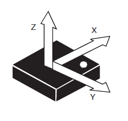
For users playing with e-puck HWRev1.3 and gumstix extension refer to section Accelerometer and gyroscope (e-puck_HWRev_1.3).
Microphone
From HWRev 1.3 the microphone sensitivity resulted a little bit different from the previous hardware revision; some empirical tests show that the difference is about ±15% so beware to adapt the thresholds in your applications if you need.
Gyroscope
The gyroscope is available from HWRev 1.3. The orientation of the gyro is shown below, the x axis points forward, the y axis points left and the z axis points upward:
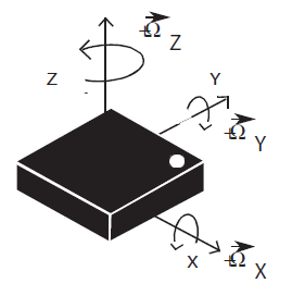
For users playing with e-puck HWRev1.3 and gumstix extension refer to section Accelerometer and gyroscope (e-puck_HWRev_1.3).
Specifications
The hardware specifications are valid for all e-puck models, except when explicitly specified with an hardware revision.
- Microcontroller: Microchip dsPIC30F6014A
- Camera: details
- HWRev 1.1: PixelPlus PO3030K CMOS image sensor, Data Sheet, no IR cut filter
- HWRev 1.2: PixelPlus PO6030K CMOS image sensor, Data Sheet, no IR cut filter
- HWRev 1.3: PixelPlus PO8030D CMOS image sensor, Data Sheet, no IR cut filter
- Bluetooth:
- HWRev 1.1: National Semiconductor LMX9820A Bluetooth Serial Port Module, Data Sheet, Software User Guide
- HWRev 1.2 and 1.3: Texas Instruments LMX9838 Bluetooth Serial Port Module, Data Sheet, Software User Guide
- Microphone: details
- Optical sensors: details
- Accelerometer: details
- HWRev 1.1 and 1.2: Freescale Semiconductor MMA7260Q three axis accelerometer, Data Sheet
- HWRev 1.3: STMicroelectronics LSM330 3D accelerometer and 3D gyroscope, Data Sheet
- Motors: details
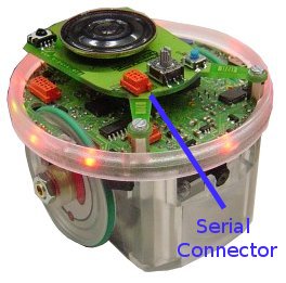
Serial communication
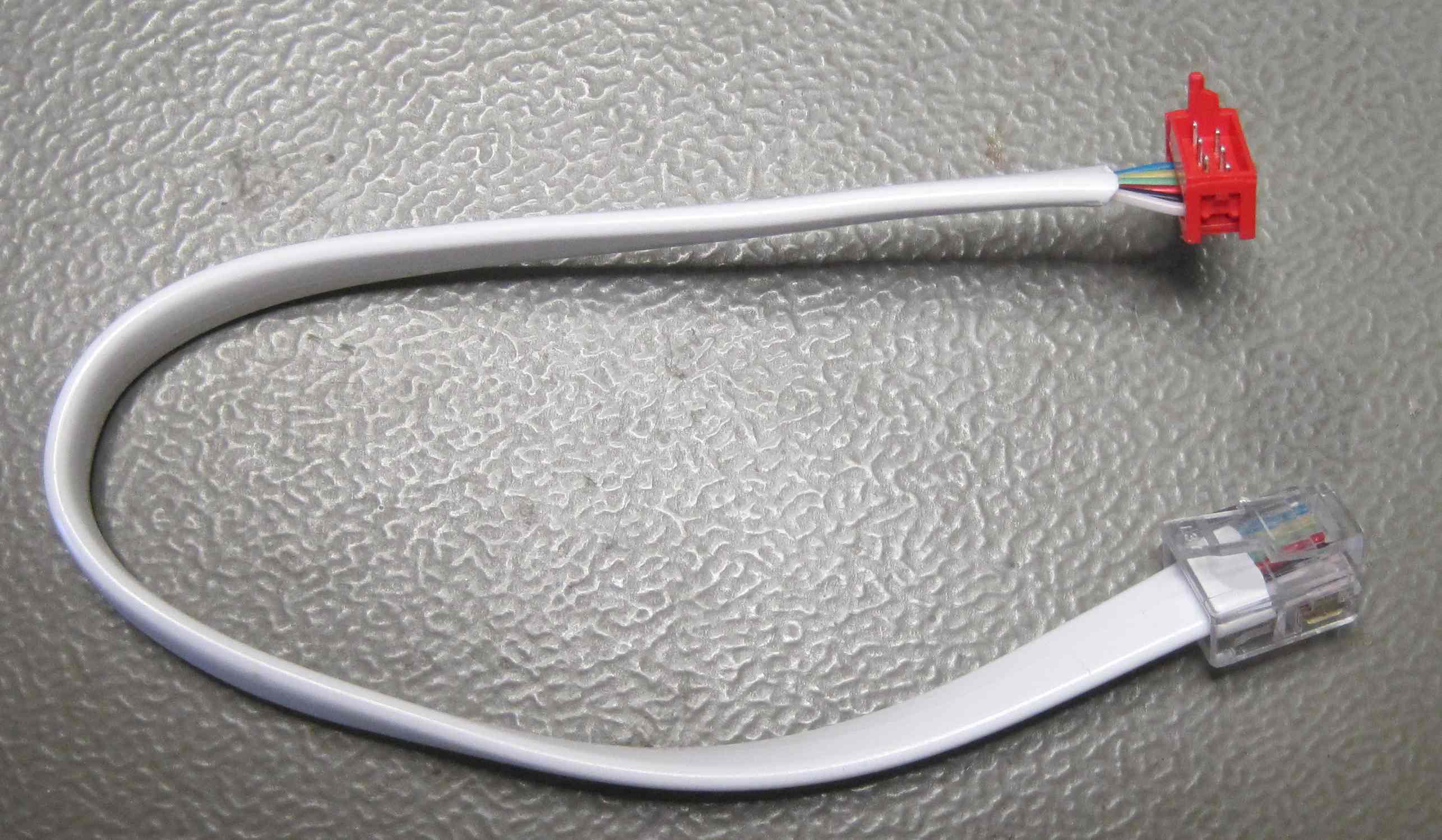
The communication between the robot and the computer can be also handled with a serial cable; the serial connector position on the robot, the related cable and the electric schema are shown on the following figures.

In order to communicate with the robot through a serial line, the robot firmware must be implemented using the functions of the UART2 instead the one of UART1 (BT). All the functions implemented for the UART1 are also available for the UART2, so it's only a matter of changing the function call names.
Anyway the standard firmware contains already a mode that communicates over serial line selecting position 11; in this mode you can configure the BT.
I2C communication
The camera, the ground sensors extension, the accelerometer (e-puck HWRev 1.3 only) and the gyro (e-puck HWRev 1.3 only) are connected to the I2C bus as slave devices (the microcontroller is the master).
The y command of the Advanced sercom protocol. can be used to read the registers values of these sensors.
For instance you can read the camera id with the following commands: y,220,0 and y,220,1 that return respectively -128=0x80 and 48=0x30 (id=8030). In the same way you can read any register with the general command y,220,REG_ADDR.
For the accelerometer you must use 60 as device address (y,60,REG_ADDR) and for the gyro you must use 212 (y,212,REG_ADDR).
The device address value to be used with the y is obtained by shifting by one position left the I2C 7-bit address of the device, for example the camera 7-bit address is 0x6E, by shifting one position left we get 0xDC=220.
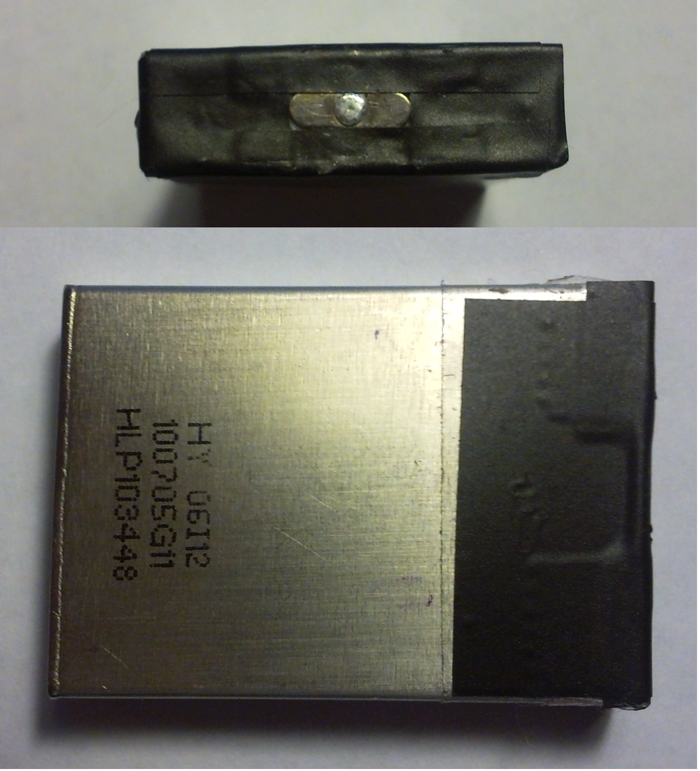
Batteries
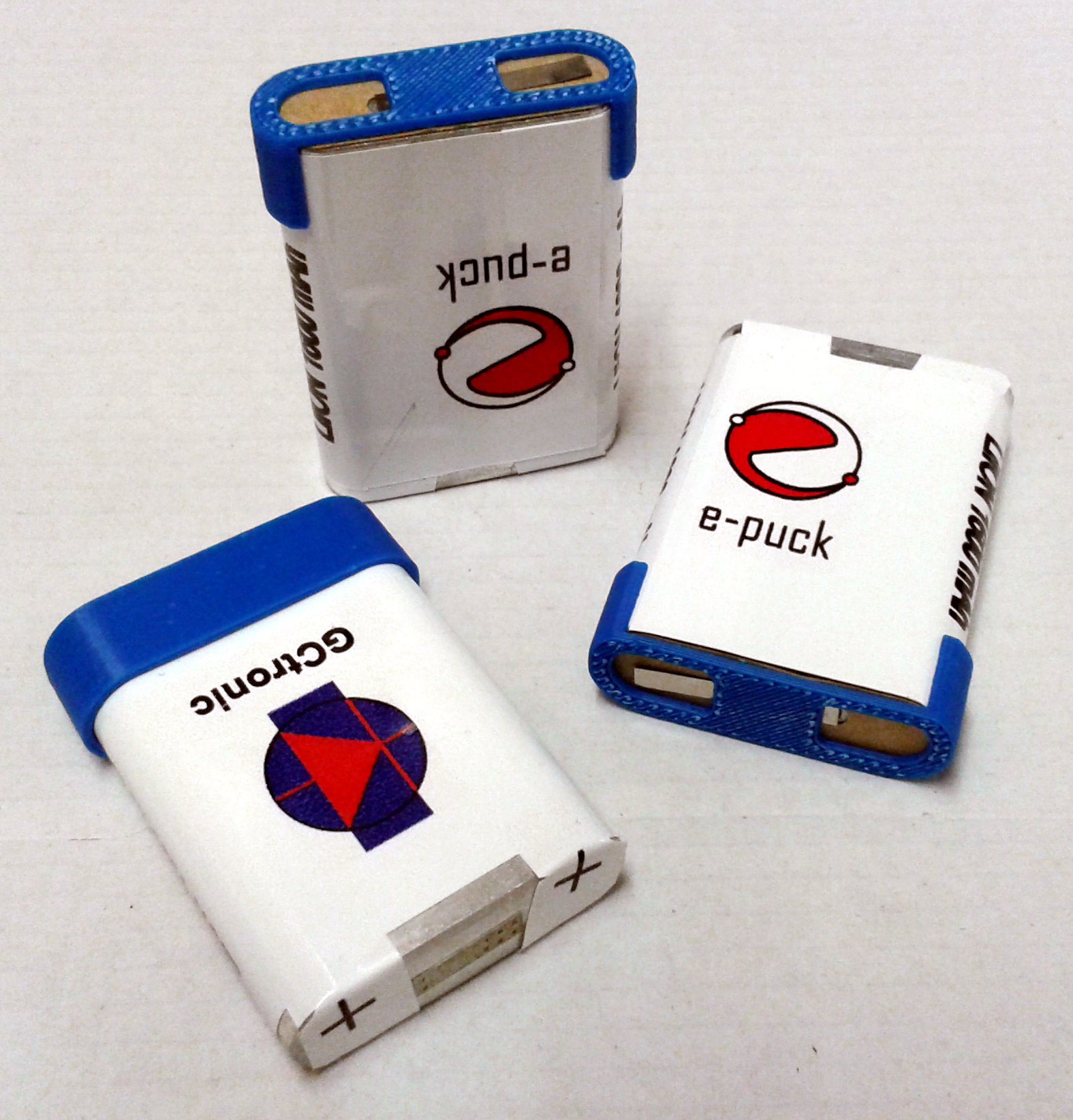
Battery from 2016 (last quarter) on
The new batteries of 2016 are bit heavier (38g) but a bit more powerful (1800 mAh). The look is similar to the previous batteries and they are of course compatible with the robot and the charger.
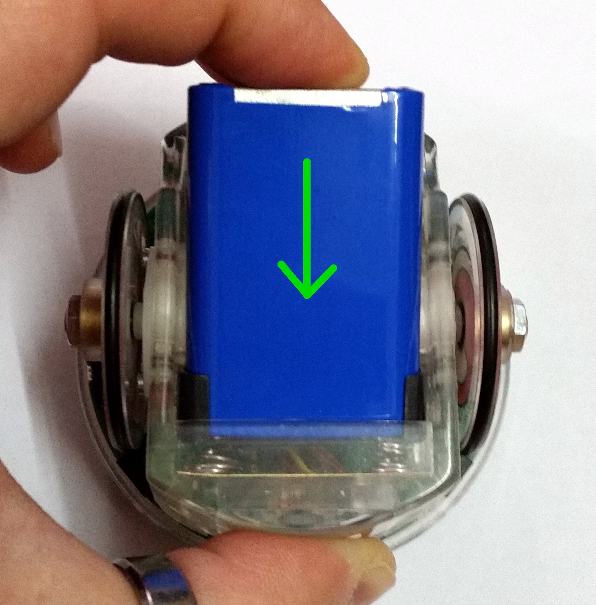
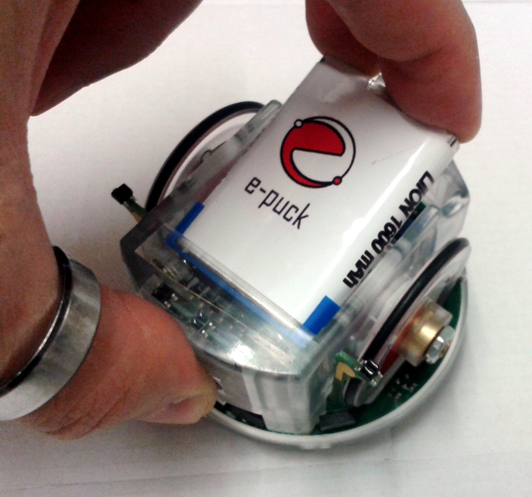
Take care when inserting the battery in the robot to not scratch the plastic sticker. You would need to apply a bit more force than before when inserting and removing the battery.
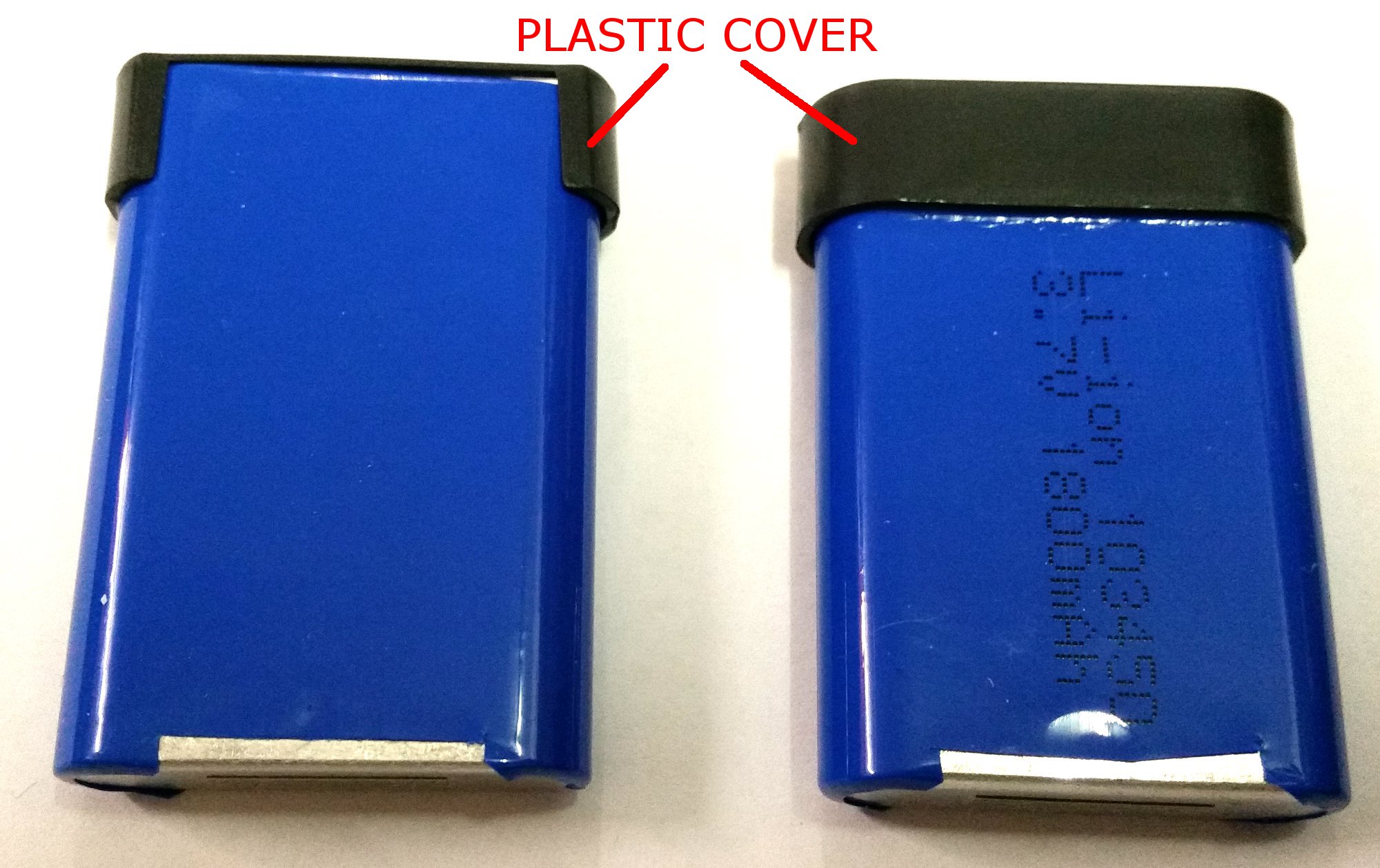
The battery is covered with a plastic protection in order to avoid any possible short circuit during inserting/removing of the battery.
The battery can be inserted only in one way: the side where the plastic protection do not cover completely the battery "top" must be towards the ground.
DO NOT REMOVE THE BLACK PLASTIC PROTECTION!
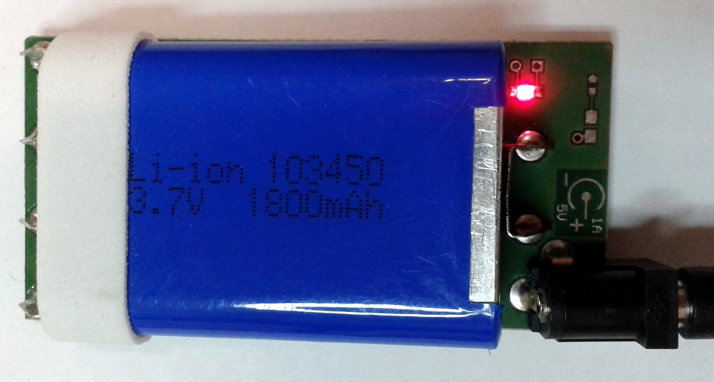
This battery doesn't fit perfectly in older chargers, but it can be inserted anyway in the charger in order to make a good contact and charge it; when the contact is ok you will see the led turned on.

Battery from 2013 to 2016
The new batteries of 2013 are lighter (33g) and a bit more powerful (1600 mAh). The look is different but they are of course compatible with the robot and the charger. Take care when inserting the battery in the robot to not scratch the plastic sticker. Is not a safety issue but keep them nice as in the beginning ;-).
The battery is covered with a plastic protection in order to avoid any possible short circuit during inserting/removing of the battery.
DO NOT REMOVE THE PLASTIC PROTECTION!
Battery up to 2012
The robots delivered in 2012 had a small difference regarding the battery; the type of battery is always the same but the mechanics of the positive pin is slightly different from one version to the other. The version with the black plastic cover comes out a bit more then the version with the brown cardboard cover.

The e-puck contact has been slightly modified to have a better contact with both versions as shown in the following figure; see the Contact-modification.pdf document to get more information on how to apply this modification.
The charger makes contact with both versions, as illustrated below.
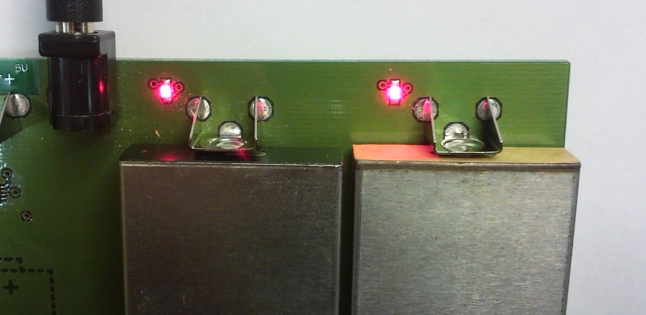
The positive pin has the tendency to get a bit oxidated and might need to be scratched a bit for a perfect connection.
Charger circuit diagram
The circuit diagram of the e-puck charger is available on the following link charger-circuit-diagram.png.
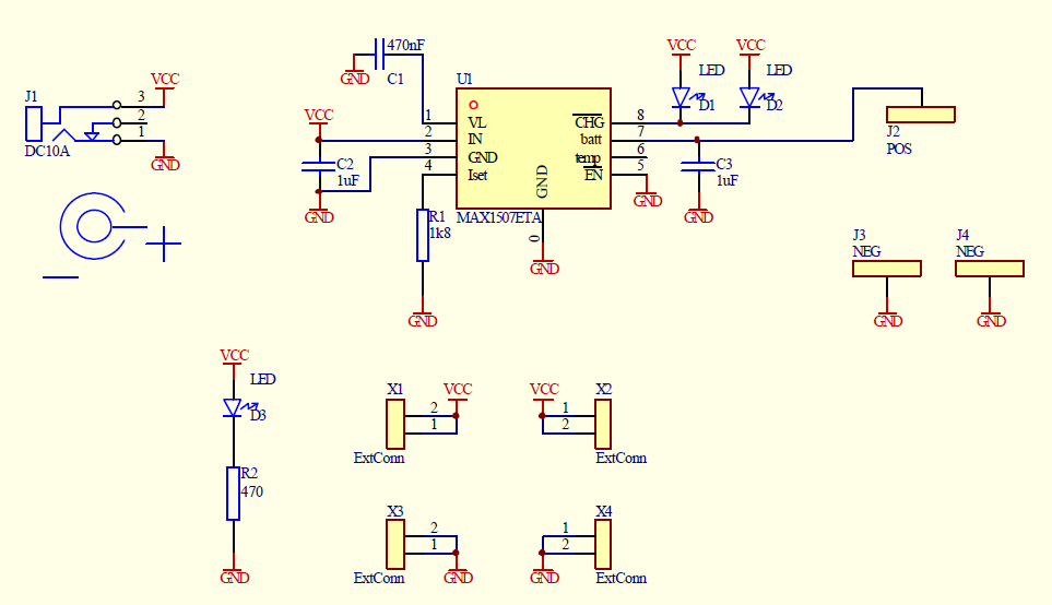
Software
The embedded software running on the e-puck is continuously extended and managed in the following git repo https://github.com/gctronic/e-puck-library. The repo comprises a complete library to work with all the sensors mounted on the e-puck and is the basis for many demos. You can download the library documentation form the following link e-puck-library.pdf.
The content of the repo is the following:
- library: this is the low level library of the e-puck
- program:
- "Bluetooth mirror": interact with the Bluetooth chip through serial cable
- "BTCom": basically it is the "asercom" implementation, refer to Advanced sercom protocol
- EPFL demo project: some nice demos bundled in one project, such as sound source location, obstacle avoidance and color blob detection (red and green). Some of these demos are included in the GCtronic standard firmware.
- GCtronic standard firmware project, refer to section Standard firmware
- tool:
- computer-side and e-puck side bootloader
- matlab interface/monitor for e-puck
- C++ interface/monitor for e-puck
Getting started
The robot is shipped with a standard firmware that let you immediately interact with the robot, follow these steps:
1) put the robot selector in position 3
2) turn on the robot and pair it with the computer:
- if you're running Linux use the system bluetooth manager to pair the robot with the computer and then issue the command sudo rfcomm bind /dev/rfcomm0 10:00:E8:C5:61:C9, where 10:00:E8:C5:61:C9 is the BT mac address of the robot
- if you're running Windows there is a detailed guide from the e-puck.org tutorials, here is a direct link to the guide BTboot epuck gettingstarted (refer to chapter 2.3, page 6)
3) execute a terminal program (e.g. minicom) and configure the connection with 115200-8N1. The serial device path should be typically something like "/dev/rfcomm0". Make sure that the flow control parameter of minicom called "Hardware" is set to "No"
4) type h+ENTER and you'll be prompted with a menu that contains all the commands you can issue to the robot, for instance you can retrieve the sensors values or turn on the leds
Standard firmware
The robot is initially programmed with a firmware that includes many demos that could be started based on the selector position. The full code is available as MPLAB project in the git repo https://github.com/gctronic/e-puck-library/tree/master/program/DemoGCtronic-complete, otherwise if only the hex file is needed it is available from DemoGCtronic-complete.hex. The project can be built with either MPLAB 8 if you're working in Windows (open the project file demoGCtronic.mcp) or MPLAB X if you're working in Windows, Mac or Linux (open the project file demoGCtronic.X from within the IDE).
Afterwards are listed all the demos and related selector position available in the standard firmware:
- Selector position 0: Shock detection. Look at runaccelerometer.h for more information.
- Selector position 1: Detect the sound source. Look at rundetectsound.h for more information.
- Selector position 2: Follow the wall. Look at runwallfollow.h for more information.
- Selector position 3: Advanced sercom protocol.
- Selector positoin 4: Let the robot move in a square path (using either odometry or gyroscope).
- Selector position 5: Sensor "feedback display".
- Selector position 6: Camera points to light.
- Selector position 7: Act like the ASL RS232 - I2C translator.
- Selector position 8: Show the ground direction. Look at rungrounddirection.h for more information.
- Selector position 9: Show the rotation rates of the gyroscope axes. Look at the rungyroscope.h for more information.
- Selector position 10: This position is used to work with the gumstix extension.
- Selector position 11: Bluetooth configuration (serial communication).
- Selector position 12: Global test (serial communication).
- Selector position 13: Uart1 to uart2 transponder.
- Selector position 14: Follow what is detected by the two front proximities detectors. Look at runbreitenberg_adv.h for more information.
- Selector position 15: Simple dust cleaner behaviour.
Project building
The standard firmware project is based on the e-puck library (refer to Software section). The library folder and the project folder must be placed at the correct positions; since the project has relative references to the library, this is the only way to build the project without missing files problems, thus:
- 1) download and extract the git repository, let say in the folder e-puck-library; you should have the following situation:
- e-puck-library
- library
- program
- tool
- 2) download and extract the project in the folder program; you should end up with the following situation:
- e-puck-library
- library
- program
- DemoGCtronic-complete
- tool
- 3) now it's possible to build the project, so open the project with MPLAB and build it; if you experience problems check the memory model for the code is set to "Large code model" (Project => Build Options => Project => MPLAB C30 tab => Memory Model) and/or try reducing the heap size (e.g. 50 bytes, Project => Build Options => Project => MPLAB LINK30 tab).
If you are working in Linux or Mac you need to download the MPLAB XC16 free compiler from Microchip and install it. After installation you need to change the project property from MPLAB X (right click on project name on the left side and then select property) in order to use the "XC16" compiler instead of the "C30" used in Windows.
For more information on the programming environment (IDE, compiler, ...) refers to section Programming.
Library
As previously mentioned the git repository includes a library to which many demos are linked. Only updates to this library that will be useful to others people and/or correct errors should be commited; some demos of this wiki makes changes to the library for the solely purpose of running the demo and thus they aren't commited to the repo.
In order to separate the original e-puck library from what is modified in the library for the current demo, all the projects (created with MPLAB) share the same structure, that is they have to be placed within the program folder of the repository and must contain only the files of the library (and their dependencies) that have been modified. An example of this structure is shown afterwards:
- e-puck-library
- library
- a_d
- bluetooth
- ...
- program
- project1
- a_d
- e_prox.c
- a_d
- project2
- ...
- project1
- tool
- library
The library folder basically never change (unless bug fixes or new features for all users are developed). All the projects have a reference to this library folder in their build options.
If some library files are modified for the current project, they are inlcuded in the project folder following the same structure of the original library, as shown for project1.
In order to build the project you then need to add all the modified library files from the project directory and all the others files from the main library folder. Not all files are always needed, it depends on the features that are used; for instance if the camera isn't used, the related library file could be omitted from the project saving memory space.
Programming
If you are interested in development of embedded applications, you should firstly choose an adequate development environment. One of the most known IDE for Windows is MPLAB Integrated Development Environment that you could download for free from the Microchip site. If you prefer to work under Linux, you can choose to use Piklab.
Writing applications in C language, instead of assembly, is much more easier; for this reason you will need a C compiler for the dsPIC30F6014A, that is the e-puck's microcontroller. For Windows there is the MPLAB C Compiler for PIC24 MCUs and dsPIC DSCs (also known as MPLAB C30) for which there are special free versions for academic use and that integrates perfectly with MPLAB IDE (you can download an old but working version directly from here); under Linux you can use the PIC30 toolchain.
Useful information for programming the e-puck can be found in the following documents:
- MPLAB C30 C COMPILER USER'S GUIDE
- MPLAB ASM30 MPLAB LINK30 AND UTILITIES USER'S GUIDE
- dsPIC30F Language Tools Quick Reference Card
MPLAB X
Recently Microchip released a new version of his IDE that is MPLAB X. This new version is multiplatform (Windows, Linux, Mac) and also the compilers can be downloaded for each platform.
Aseba
Aseba is a set of tools which allow novices to program robots easily and efficiently, refere to https://www.thymio.org/en:start for more information.
Here is the page with the basic information needed to start working with Aseba and the e-puck robot https://www.thymio.org/en:e-puck.
You can download an MPLAB X project based on the git repo https://github.com/aseba-community/aseba-target-epuck in the following link aseba.zip; place it in the "e-puck-library/program" folder (refer to section http://www.gctronic.com/doc/index.php/E-Puck#Library for more information on how to build).
You can download the last aseba firmware for the e-puck from the following link aseba-target-epuck.hex.
Beware that at the moment the only bootloader capable of uploading the aseba-target-epuck.hex to the robot is the Linux version.
Python
Python is a widely used programming language supported by a large and comprehensive standard library. A Python library is available enabling the remote control of the e-puck robot, read the sensors values, control the motors while running the heavy processes on a computer. You can start playing with the e-puck and Python by downloading the e-puck python package, it contains:
- Python 2.6.6
- Python setup tools
- e-puck Python library: source
- e-puck Python library dependencies: pybluez, Python imaging library
- some examples (refers to examples)
Follow these steps to install Python and run your first Python example (this instructions are for Windows but the procedure should be similar also for Linux and Mac OS):
- Install Python (the executable python-2.6.6.msi is in the Python2.6 directory)
- Install the Python setup tools by running the script ez_setup.py you find in the Python2.6 directory:
- issue the command python ez_setup.py in a terminal
- alternatively you can download an IDE that will help you in programming, run and debug your code; a valid IDE is called PyCharm
- Install e-puck Python library dependencies:
- install pybluez by issueing the command python setup.py install in a terminal (be sure to be in the dependencies\pybluez-master directory)
- install the PIL library by executing PIL-1.1.7.win32-py2.6.exe you find in the dependencies directory
- Program the e-puck with the last standard firmware and put the selector in position 3
- Configure the Bluetooth connection with the e-puck in the computer (add Bluetooth device and insert its pin)
- when you add the e-puck robot as Bluetooth device, right click on the device and choose property; in the "Bluetooth" tab you'll find the mac address (something like 10:00:e8:c5:61:c9). Copy this address since you'll need it to connect to the robot when running the Python scripts
- In the examples directory you'll find the e-puck library ePuck.py and 3 examples braitenberg.py, line_follower.py, photo_taker.py
- the ePuck.py file must be placed in the same directory as your script
- to run an example issue the command python script_name.py mac_address, where script_name is either braitenberg or line_follower or photo_taker and mac_address is the address that you previously annotate (e.g. 10:00:e8:c5:61:c9)
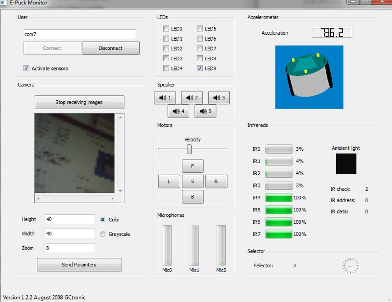
PC interface
An interface running on a computer and connecting to the e-puck through bluetooth based on the advanced sercom protocol (selector 3) was developed; from this interface it's possible to have information about all the sensors, receive camera images and control the leds and motors. The source code is available from the following links:
- Multiplatform version 3.0 (Monitor3.0 source code); the application is a Qt project, so the compilation may be handled easily with Qt Creator; alternatively qmake can be used. The following executables are compiled dynamically, so the Qt library (4.5.0 or higher) must be installed in the system in order to run them:
- Linux executable: before running the executable, type "chmod +x file"
- MacOS executable
- Windows executable (+ dlls); tested on Windows XP, Windows Vista, Windows 7, Windows 10
Since the last version comprises a basic OpenGL representation of the e-puck you will need also the OpenGL extension libraries in order to compile the project; these should be included in the Qt SDK, but if you encounter problems refers to http://doc.trolltech.com/4.6/qtopengl.html#details; basically you need to download manually the OpenGL libraries: GLX (Linux), CGL (MacOS), WGL (Windows).
Once the project is built dynamically, some errors about missing dll may be thrown; one of these missing libraries could be the mingwm10.dll. Others could be related to Qt. To solve the problem you need either to build the project statically, or to register the libraries on the system, or to manually include all the dll with the executable.
Examples
Basic demos
The following set of simple programs for the e-puck has an increasing degree of complexity, from very basic LED blinking up to motor control depending on sensor input; it's a good starting point for beginner users. The first demos do not use interrupts and keep to a minimum the use of the library.
You can download the set of these demos from this link BasicDemos.zip.
A list of these basic programs is listed below:
- demo0: very simple LEDs blinking
- demo1: LEDs blinking (pause with timer)
- demo2: selector reading + LEDs
- demo3: send selector position via Bluetooth (simplified method)
- demo4: proximity reading with interrupts + LEDs
- demo5: proximity reading with interrupts + LEDs + send values via BT (assembler version with interrupt and buffer)
- demo6: motor speed controlled depending on front proximity sensor values
Compilation: the demos can be edited and compiled using MPLAB IDE (windows), clicking directly on the project file. The demos should be compiled with MPLAB-C30 on all operating systems. The compiled .hex file is downloaded to the e-puck robot via Bluetooth using for example tinyBootloader.
Audio recording
This demo program (hex file, MPLAB project) let the e-puck recording for about two seconds whatever you like and then reproduces it infinitely.
The program starts with a led animation (flow) and then turns all leds on for about two seconds, this is the moment for recording; note that only the right micro (mic0) is used.
It's possible also to choose the volume/amplification of the reproduction using the selector (from 1 to 16).
Still images
This demo program is optimized to let the robot handle images with resolution up to 640x480 pixels (the maximum reachable by the camera); after acquisition, the robot sends the images to a computer through bluetooth. This zip ImageReceiverBT.zip contains both the program for the robot (hex file) and the application for the computer (Windows platform). The selector of the robot must be in position 3.
You can find the sources for the application running on the computer side from this link ImageReceiverBTsrc.rar.
You can find the MPLAB project for the application running on the robot from this link DemoGCtronic-vga-images.zip.
Bootloader
- Windows: Tiny Bootloader v1.10.6 or Tiny Multi Bootloader+
- Linux: epuck-bootloader-linux.zip
- requirements:
sudo apt-get install libbluetooth-dev
- requirements:
- Mac OS: https://github.com/gctronic/e-puck-library/tree/master/tool/bootloader/computer_side/multi_platform
- actually it is a Perl script, thus in principle it could be used also in Linux and Windows
- after pairing with the robot, you should issuing a command similar to
./epuckupload -f firmware.hex /dev/tty.e-puck_3675-COM1and then press the reset button on the robot
Others tools
From the official e-puck site you can find information about others software tools available for the e-puck robot in the following link http://www.e-puck.org/index.php?option=com_content&view=article&id=18&Itemid=24.
Local communication
An example of such tools is the libIrcom, a local communication library exploiting the proximity sensors placed around the robot to modulate infrareds.
If an higher throughput and longer communication distance are required, there is the range and bearing extension designed for this purpose.
ROS
This chapter explains how to use ROS with the e-puck robots; basically all the sensors are exposed to ROS and you can also send commands back to the robot through ROS. Both Pyhton and cpp versions are implemented to give the user the possibility to choose its preferred programming language. Here is a general schema:
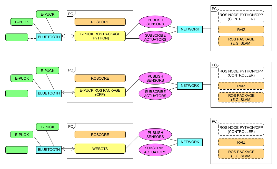 Click to enlarge
First of all you need to install and configure ROS, refer to http://wiki.ros.org/Distributions for more informations. Alternatively you can download directly a virtual machine pre-installed with everything you need, refer to section virtual machine; this is the preferred way.
- This tutorial is based on ROS Hydro.
- If you downloaded the pre-installed VM you can go directly to section Running the ROS node.
The ROS epuck driver was initially developed by the Verlab Laboratory at Universidade Federal de Minas Gerais, the related code can be found in the following repository https://github.com/verlab-ros-pkg/epuck_driver. It is based on rospy (Python). We extended the initial driver to support all the e-puck sensors, the code can be found in the following repository https://github.com/gctronic/epuck_driver.
Starting from the work done with the ROS epuck driver for python, we developed another ROS node based on roscpp that has the same functionalities; the code can be found in the following repository https://github.com/gctronic/epuck_driver_cpp.
Initial configuration
The following steps need to be done only once after installing ROS:
- 1. If not already done, create a catkin workspace, refer to http://wiki.ros.org/catkin/Tutorials/create_a_workspace. Basically you need to issue the following commands:
  mkdir -p ~/catkin_ws/src
  cd ~/catkin_ws/src
  catkin_init_workspace
  cd ~/catkin_ws/
  catkin_make
  source devel/setup.bash
- 2. You will need to add the line
source ~/catkin_ws/devel/setup.bashto your .bashrc in order to automatically have access to the ROS commands when the system is started - 3. Clone the ROS epuck driver repo:
- if you are working with Python: from https://github.com/gctronic/epuck_driver; you'll have a directory named epuck_driver that is the repo local copy
- if you are working with cpp: from https://github.com/gctronic/epuck_driver_cpp; you'll have a directory named epuck_driver_cpp that is the repo local copy
- 4. Copy the repo directory epuck_driver or epuck_driver_cpp (this is the actual ros package) inside the catkin workspace source folder (~/catkin_ws/src)
- 5. Install the dependencies:
- Python:
- The ROS epuck driver is based on the e-puck Python library that requires some dependencies:
- install the Python setup tools:
sudo apt-get install python-setuptools - install the Python image library:
sudo apt-get install python-imaging - install pybluez:
- download pybluez and extract it
- install pybluez dependencies:
sudo apt-get install libbluetooth-dev - go to the pybluez directory and issue the command
python setup.py install
- install the Python setup tools:
- The ROS epuck driver is based on the e-puck Python library that requires some dependencies:
- cpp:
- install the library used to communicate with Bluetooth:
sudo apt-get install libbluetooth-dev
- install the library used to communicate with Bluetooth:
- Python:
- 6. Open a terminal and go to the catkin workspace directory (~/catkin_ws) and issue the command
catkin_make, there shouldn't be errors - 7. Program the e-puck with the last standard firmware and put the selector in position 3
Running the ROS node
First of all get the last version of the ROS epuck driver from github:
- Python: clone the repo https://github.com/gctronic/epuck_driver and copy the epuck_driver directory inside the catkin workspace source folder (e.g. ~/catkin_ws/src)
- cpp: clone the repo https://github.com/gctronic/epuck_driver_cpp and copy the epuck_driver_cpp directory inside the catkin workspace source folder (e.g. ~/catkin_ws/src)
Finally build the driver by opening a terminal and issueing the command catkin_make from within the catkin workspace directory (e.g. ~/catkin_ws).
If you're using Pyhton make sure the node is marked as executable by opening a terminal and issueing the following command from within the catkin workspace directory (e.g. ~/catkin_ws): chmod +x ./src/epuck_driver/scripts/epuck_driver.py.
Now you can finally start the ROS node, for this purposes there are two launch scripts (based on roslaunch), one for working with a single robot and the other to work with multiple robots. Before actually starting the node you need to configure the e-puck robot as Bluetooth device in the system and copy its mac address (this will be needed when launching the ROS node); if you want to work with multiple robots you need to add all of them as Bluetooth devices in the system and copy all the mac addresses. The procedure to add a Bluetooth device is:
- Go to System Settings (left panel has a link)
- Click on Bluetooth
- Click on the + sign in the bottom left of the window to start the procedure
- Turn on the robot and click continue, now the search is started and after a little while the robot should appear on the list of found devices
- Click on PIN Options..., select Cutom PIN, enter the correct robot PIN (robot id) and click Close
- Now click Continue and the robot will be paired
- To know the mac address of a paired robot, go to System Settings, Bluetooth and select the robot; once selected you'll see in the right side the related mac address
The ROS e-puck driver based on roscpp has the possibility to automatically search for the robots, so you don't need to specify the mac address but you need to pass only the robot id; pay attention that you still need to pair the robot to the computer as explained in the previous steps. Anyway is recommended to specify the mac address to speed up and facilitate the connection (especially with multiple robots).
First thing to do before launching the script file is running the roscore, open another terminal tab and issue the command roscore.
Single robot
Open a terminal and issue the following command:
- Python:
roslaunch epuck_driver epuck_controller.launch epuck_address:='10:00:E8:C5:61:C9'. - cpp:
roslaunch epuck_driver_cpp epuck_controller.launch epuck_id:='3000' epuck_address:='10:00:E8:C5:61:C9'.
10:00:E8:C5:61:C9 is the e-puck Bluetooth mac address and 3000 is the e-puck id (number on the case).
If all is going well you'll see the robot make a blink meaning it is connected and ready to exchange data (the blink is done only when using the Python ROS driver) and rviz will be opened showing the informations gathered from the topics published by the epuck driver node. The following graph shows all the topics published by the epuck driver node (Pyhton):
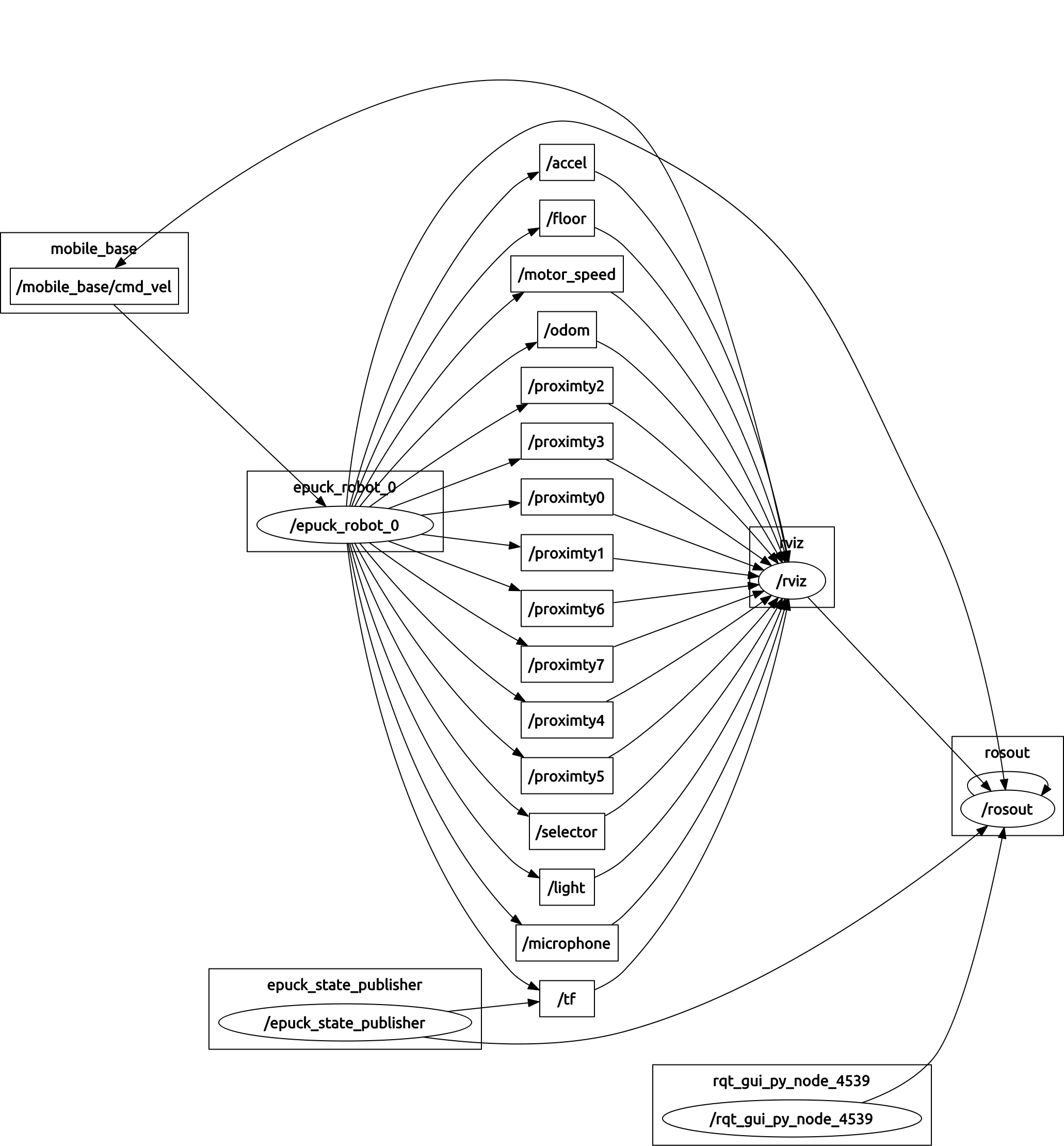 Click to enlarge (Python)
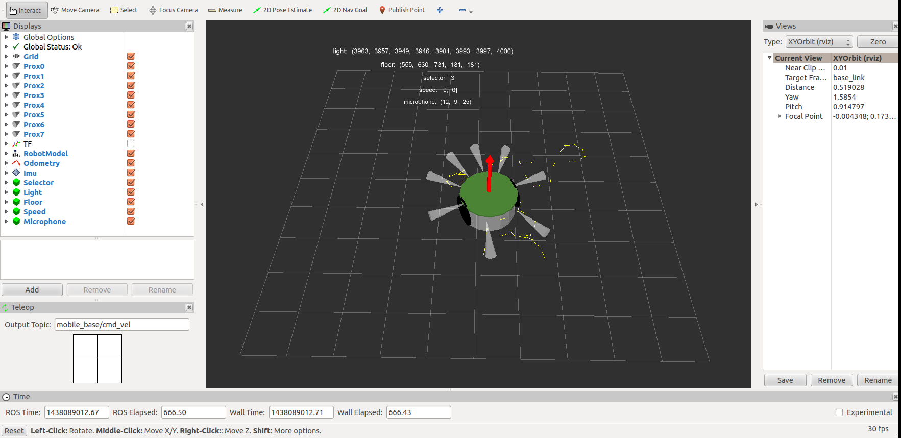 Click to enlarge
Cpp ROS driver
The cpp ROS driver launch script is configured also to run the gmapping (SLAM) node that let the robot construct a map of the environment; the map is visualized in real-time directly in the rviz window. Here is a video:
Multiple robots
The script is designed to work with 4 e-puck robots and you need to modify the script in order to use the correct Bluetooth mac addresses:
- open the file ~/catkin_ws/src/epuck_driver/launch/multi_epuck.launch (Python) or ~/catkin_ws/src/epuck_driver_cpp/launch/multi_epuck.launch (cpp)
- on top of the file you'll see a list of 4 e-puck addresses, change their values accordingly
Now you can start the node by issueing the following command in a terminal:
- Python:
roslaunch epuck_driver multi_epuck.launch - cpp:
roslaunch epuck_driver_cpp multi_epuck.launch
If all is going well you'll see the robots make a blink meaning they are connected and ready to exchange data (the blink is done only when using the Python ROS driver) and rviz will be opened showing the proximity and odometry of all the 4 robots; it is assumed that the robots are placed in a square (each robot in each corner) of 20 cm.
In order to move the robots you can either use a TV remote or you can directly use ROS by publishing velocities commands by issueing the following command:
rostopic pub -1 /epuck_robot_0/mobile_base/cmd_vel geometry_msgs/Twist -- '[4.0, 0.0, 0.0]' '[0.0, 0.0, 0.0]'
- this command will move the first e-puck with a linear velocity of 1 rotation per second (robot moves straight)
- only the x component of the linear velocity and the z component of the angular velocity are used
- for more information on the Twist message refer to http://docs.ros.org/api/geometry_msgs/html/msg/Twist.html
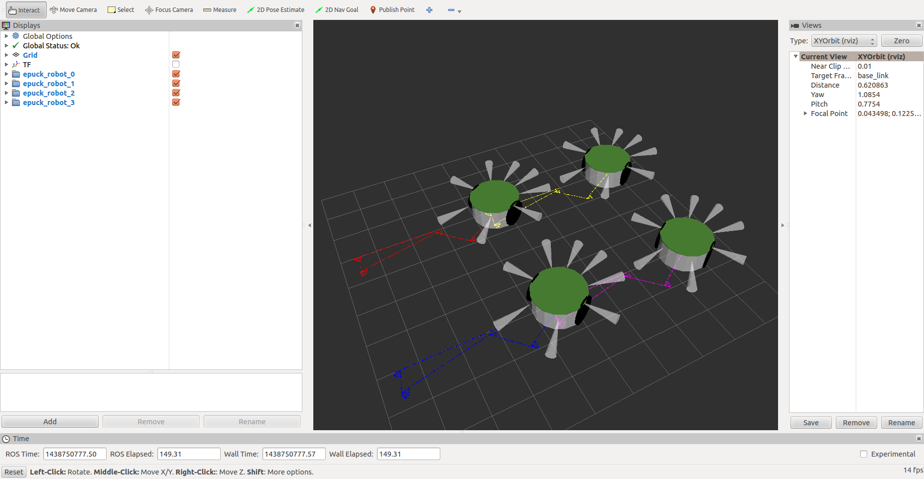 Click to enlarge
Visualize the camera image
In order to visualize the image through ROS you need to use the launch script for a single robot with an additional parameter cam_en as follows:
- Python:
roslaunch epuck_driver epuck_controller.launch epuck_address:='10:00:E8:C5:61:C9' cam_en:='true' - cpp:
roslaunch epuck_driver_cpp epuck_controller.launch epuck_id:='3000' epuck_address:='10:00:E8:C5:61:C9' cam_en:='true'
Then with the Python ROS driver you need to open another terminal and issue the command rosrun image_view image_view image:=/camera that will open a window wiht the e-puck camera image.
With the cpp ROS driver the image is visualized directly in the rviz window (on the right), as shown in the following image:
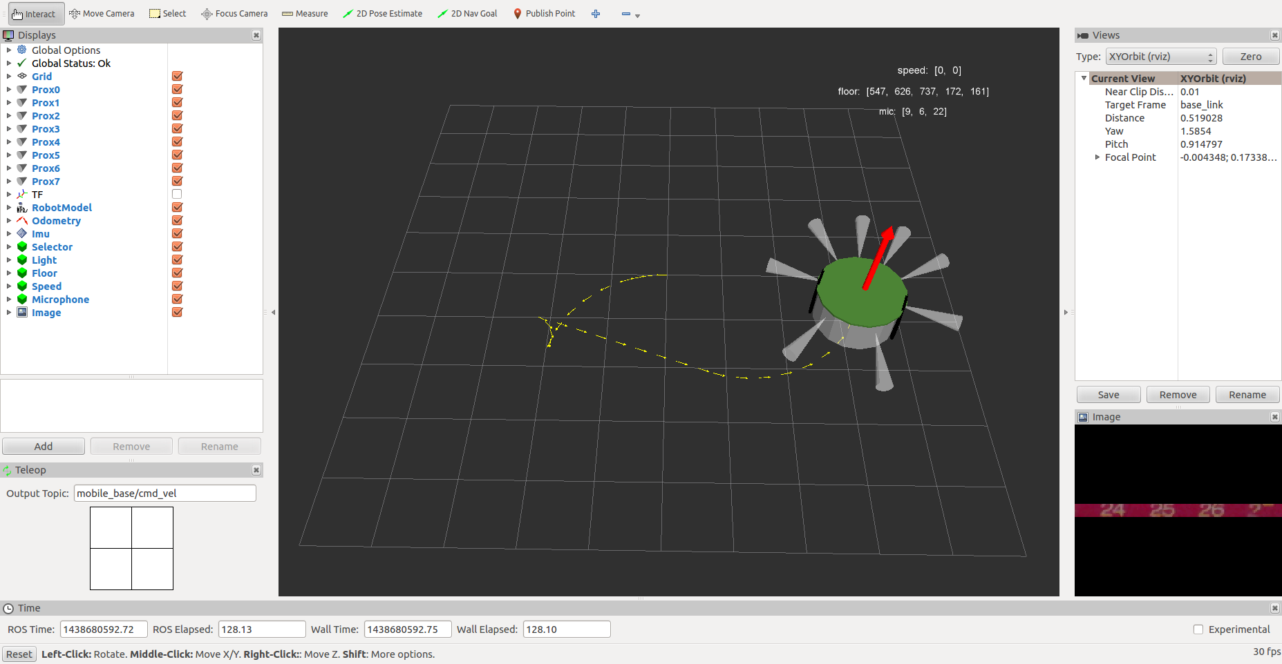 Click to enlarge
Virtual machine
To avoid the tedious work of installing and configuring all the system we provide a virtual machine which includes all the system requirements you need to start playing with ROS and e-puck. You can download the image as open virtualization format from the following link ROS-Hydro-12.04.ova (based on the VM from http://nootrix.com/2014/04/virtualized-ros-hydro/); you can then use VirtualBox to import the file and automatically create the virtual machine. Some details about the system:
- user: gctronic, pw: gctronic
- Ubuntu 12.04.4 LTS (32 bits)
- ROS Hydro installed
- PyCharm: Python IDE used to extend the rospy e-puck driver; when you open the IDE it will open a project pointing to the ROS e-puck driver so you can immediately start diving into the code
- Webots 8.0.5 is installed (last version available for 32 bits linux)
- git-cola (git interface) is installed
- the catkin workspace is placed in the desktop
If you encounter problems related to network adapters not recognized when booting the imported virtual machine then you need to follow these steps:
- close VirtualBox
- go to the directory C:\Users\YOUR_USER\VirtualBox VMs\ROS Hydro - 12.04
- open the file ROS Hydro - 12.04.vbox with a text editor, remove all the content of the <Network tag and save
- open VirtualBox, select "ROS Hydro - 12.04" and under settings enable the network card (if you need it)
- start the virtual machine
Webots
The Webots simulator integrates a ROS controller that publishes the sensor data of the e-puck robot in ROS, then we can exploit the multitude of packages available in ROS to process the sensors data and simulate the behavior of the e-puck by issueing commands through ROS.
Once we're satisfied with the results in the simulator, we can test our algorithms in the real world by remote controlling the e-puck through Webots.
The following steps shows how to run the example included in Webots that let the e-puck follow a line using ROS:
- Install the last version of Webots following the instructions; pay attention that starting from Webots 8.1.0 the support to linux 32 bit was dropped. The following instructions are based on Webots 8.2.1 and Ubuntu 14.0.4 64 bits (you can download a pre-installed virtual machine with ROS and Ubuntu from http://nootrix.com/downloads/#RosVM.
- Create a catkin workspace as explained in section Initial configuration if you didn't already done
- Copy the directory nodes from WEBOTS_MODULES_PATH/projects/languages/ros/ (e.g. /home/viki/.local/share/Cyberbotics/Webots/8.2/projects/languages/ros/) to the catkin workspace source folder (e.g. ~/catkin_ws/src)
- Copy the directory srv from WEBOTS_MODULES_PATH/projects/default/controllers/ros/include (e.g. /home/viki/.local/share/Cyberbotics/Webots/8.2/projects/default/controllers/ros/include) to the nodes package just copied (e.g. ~/catkin_ws/src/nodes)
- Open a terminal and go to the catkin workspace directory (~/catkin_ws) and issue the command
catkin_make - Open another terminal and start ROS by typing
roscore - Start Webots and open the ROS e-puck example: File => Open Sample World => languages => ros => e-puck_line.wbt and play it
- Now from the terminal positioned to the catkin workspace issue the command
rosrun nodes e-puck_line 60, where 60 is the duration in seconds; you should see the e-puck follow the line in the simulator
For more information have a look at the Readme you can find in WEBOTS_MODULES_PATH/projects/languages/ros/nodes (e.g. /home/viki/.local/share/Cyberbotics/Webots/8.2/projects/languages/ros/nodes) or refer to the Webots user guide chapter Using ROS.
The EDU license is valid to play with Webots and ROS (PRO license not required).
Webots ROS SLAM with e-puck
This example shows how to use the gmapping (SLAM) package of ROS to let the e-puck robot construct a map of the simulated environment; the map is visualized in real-time directly in the rviz window. Here are the steps to run the demo:
- download the code from the following link webots-ros-slam.zip and extract the zip
- copy the source file nodes/src/e-puck_line_slam.cpp to the catkin workspace folder of the Webots nodes (e.g. ~/catkin_ws/src/nodes/src)
- copy the folders nodes/config, nodes/launch and nodes/urdf to the catkin workspace folder of the Webots nodes (e.g. ~/catkin_ws/src/nodes/)
- copy the files nodes/CMakeLists.txt and package.xml to the catkin workspace folder of the Webots nodes (e.g. ~/catkin_ws/src/nodes/) by substituting the current ones
- Open a terminal and go to the catkin workspace directory (~/catkin_ws) and issue the command
catkin_make - Open another terminal and start ROS by typing
roscore - Start Webots and open worlds/e-puck_line_slam.wbt: File => Open World => look for the directory containing e-puck_line_slam.wbt and play it
- Now from the terminal positioned to the catkin workspace issue the command
roslaunch nodes epuck_controller.launch
Here is a video:
Webots ROS and OpenCV with e-puck
This example shows how to integrate OpenCV with ROS to let the e-puck robot detect and follow a ball in the simulated environment. Here are the steps to run the demo:
- download the code from the following link webots-ros-opencv.zip and extract the zip
- copy the source file nodes/src/e-puck_opencv.cpp to the catkin workspace folder of the Webots nodes (e.g. ~/catkin_ws/src/nodes/src)
- copy the files nodes/CMakeLists.txt and package.xml to the catkin workspace folder of the Webots nodes (e.g. ~/catkin_ws/src/nodes/) by substituting the current ones
- Open a terminal and go to the catkin workspace directory (~/catkin_ws) and issue the command
catkin_make - Open another terminal and start ROS by typing
roscore - Start Webots and open worlds/e-puck_opencv.wbt: File => Open World => look for the directory containing e-puck_opencv.wbt and play it
- Now from the terminal positioned to the catkin workspace issue the command
rosrun nodes e-puck_opencv 20 140 0 0 150 255 255, where
- 20 is the duration in seconds
- 140, 0, 0 are the min H, S and V respectively of the blob to detect
- 150, 255, 255 are the max H, S and V respectively of the blob to detect
E-puck gumstix extension
For more information on how to use ROS with the e-puck gumstix extension refer to section http://www.gctronic.com/doc/index.php/Overo_Extension#ROS.
Test and Results
Bluetooth Communication Testing - PC to robot
Some tests were performed in order to analyze the bluetooth speed between a computer and the e-puck; the following three experiments were executed sending the same total amount of data but differently subdivided:
- 19200 packets of 6 bytes each sent from computer to e-puck: about 65 seconds (BTspeed.zip)
- 2560 packets of 45 bytes each sent from computer to e-puck: about 20 seconds (BTspeedPackets.zip)
- 1 packet of 115200 bytes sent from computer to e-puck: about 10 seconds (BTspeedFile.zip)
Explanation: dividing a packet in small chunk of data (such as a single command) introduces pauses generated by the Bluetooth device of the PC. The mean measured delay time between a packet and the other is about 3 ms, but could be as high as 20 ms. Sending the packet in one single block like in the third experiment, has no pauses and thus needs exactly the theoretical time of 10 seconds for the channel at 115'200 Baud.
Bluetooth Communication Testing - robot to robot
Some tests were performed also to analyze the maximum speed reachable between two robots using direct communication, that is one acting as the master and the other as the slave. The Bluetooth 2.0 specification asserts 1 Mbit/s air data rate, but in practice with the Bluetooth protocol overhead the usable bandwidth is lower; moreover in our case there are others two facts to take in consideration:
- the communication between the robot and the BT chip is configured to be at 115200 bps
- the buffer handling system of the BT chip is capable of receive at maximum 200 packets per second (refers to UART buffer AN.pdf)
From the tests the resulting throughput is 18 Kb/s, sending a total of 41000 bytes with 41 bytes for each packet and waiting the response from the chip before sending the next packet; moving the slave device several meters away from the master influences the communication speed, that slows down.
The sources (MPLAB project) of the firmware used for this test can be downloaded from the following link DemoGCtronic-BT.zip (master=selector position 9, slave=selector position 4).
There is an additional example that shows how to establish a direct Bluetooth link between two e-pucks. This firmware is intended to be programmed on the master robot (selector 0); the master will send commands using the "asercom protocol" to a slave robot, that is the first robot found during the search, in order to turn on its leds in sequence. The slave robot is intended to be programmed with the standard firmware (selector position 3).
You can download the MPLAB X project from here DemoGCtronic-BT-asercom.zip; in order to build refer to section Project_building. The Bluetooth library was extended to build this demo, you can download it from here bluetooth.zip; this library must replace the one included in the e-puck library in order to build the project.
e-puck balancing
The users can transform the e-puck in a self balancing robot by applying some mechanical modifications as shown in the following figure. Here are the 3d models of the wheel tyre extension and spacer. For more information on the assembly please contact us.
 Click to enlarge
Here is a video of the e-puck trying to self balance; this is only a starting point to demonstrate the feasiblity, so you can take the code (MPLAB X project) and improve it.
e-puck and Arduino
The Arduino boards are used widely in the hobby community and you can extend the functionalities of a board by using the so called shields; there are tons of shields like WiFi, SD reader/writer, battery, XBee, GSM, speech recognition, rfid, ... there is a shield for everything (almost). For these reasons we decided to connect an Arduino to the e-puck robot.
I2C is used to communicate between the e-puck (master) and the Arduino (slave), this is the easiest way to get both a communication channel and the power from the e-puck thanks to an already available connector on the robot. The connector is placed on the bottom side of the e-puck main pcb as shown in the following figures:

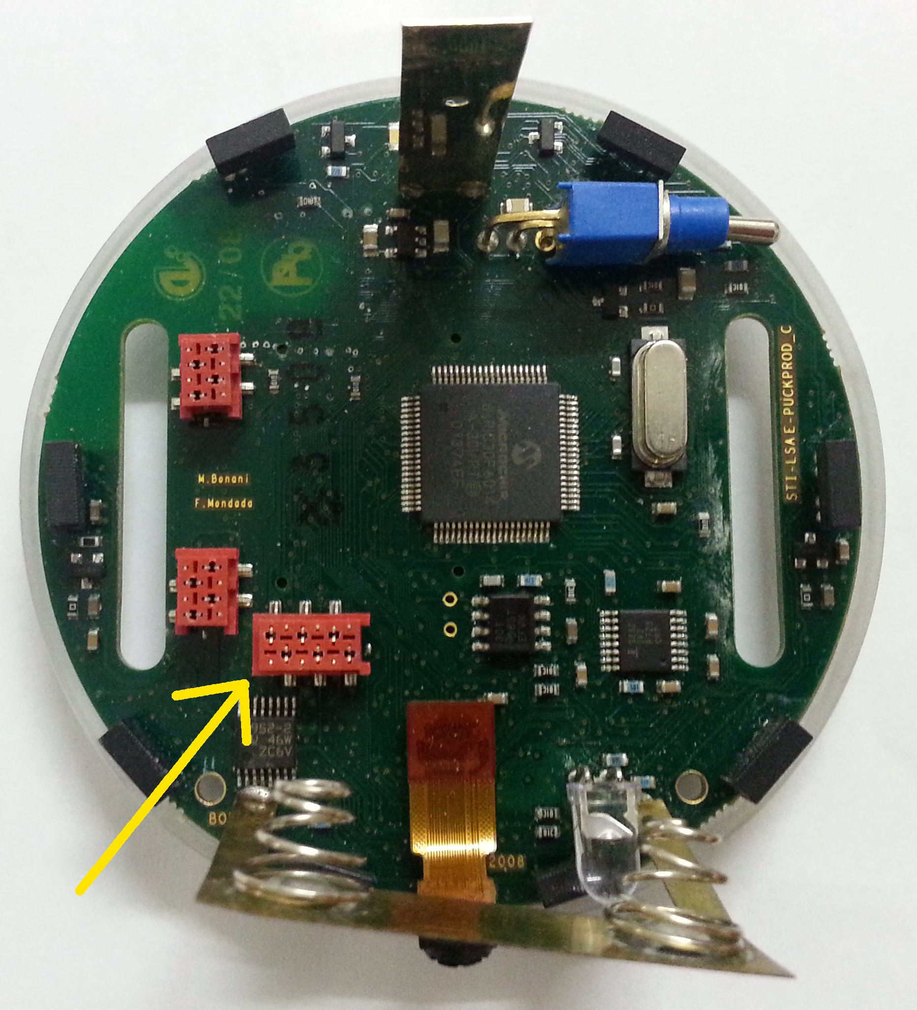 Click to enlarge
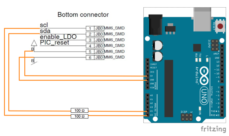
The following figure shows the schema to connect the e-puck to the Arduino Uno board; you can follow the same schema to connect to other Arduino boards paying attention to the related pinout.
Power and voltage considerations: in this configuration, the e-puck battery (LiPo 3.7Volt) powers directly also the Arduino board to its 5 Volt line. This is ok for the tested demos but it might be limiting in some rare cases. Let us know your goals and experiments to get support. The I2C lines are simply protected with 2 series resistors in order to limit any excessive current into the PIC.
 Click to enlarge
Here is a video of a demo in which you can control the e-puck with your voice; the e-puck is connected to an Arduino Uno that is extended with an Easy VR shield for speech recognition.
The source code of the demo is available in the following links: MPLAB project for the e-puck, Arduino IDE (1.6.6) project for the Arduino Uno board (you'll need the Easy VR Arduino library to build the project).
A test project that works without any shield is available in the following link Arduino IDE (1.6.6) test project, this demo rotates continuously the robot right and left. It works with the same robot firmware as the previous demo.
We designed a support in order to mechanically attaching the Arduino board on top of the e-puck robot as shown in the following figure.
 Click to enlarge
Here is the support 3D model that you can print with your 3d printer. Alternatively you can purchase an "e-puck arduino set" from the shop.
Known problems
Re-flashing the bootloader on e-puck
In some cases it was reported that the internal bootloader on e-puck was corrupted due to a malfunction of the last code upload.
In those cases the bootloader (demoGCtronic-rev117+bootloader.hex) has to be re-flashed on the robot via cable (see figure) with ICD2 and MPLAB IDE or compatible HW and SW.
See the procedure (Instruction re-program bootloader.pdf) and in case of need contact info[at]gctronic.com.

Uncorrect/unknown bluetooth PIN code
In a couple of rare cases it was reported that the PIN code of the Bluetooth chip was not anymore the usual one (same as e-puck number). It seems that
the issue is linked to trials of robot to robot direct communication. One robot could have picked up the PIN of the other one, so you could try that PIN to get access to the robot. Another possibility is to try the default pin number 0000.
In order to restore the name and pin number of the robot you can either make a program specifically for this purpose (1) or use the standard firmware but you would need the serial cable (2):
- the e-puck library contains the functions to interact with the BT chip and change all its configurations including pin number and friendly name; for a code example refer to the example DemoBTConfiguration.zip, that simply rewrite the pin and friendly name (change only the pin number in the code, the friendly name will be changed accordingly). Another source of insipiration is the Standard_firmware, the part of the code related to selector 11. In case the chip isn't responding be sure it is in command mode (use the function
e_bt_exit_tranparent_mode). - program the robot with the Standard_firmware and put the selector in position 11. Connect the serial cable to the robot as shown in section Serial_communication and to the computer (you would need an USB to serial adapter); open the port using this configuration 115200n8. Once the communication channel is opened type the command
H+enterto get the help. You can get the serial cable from the shop.
Battery isolation (for battery up to 2012)
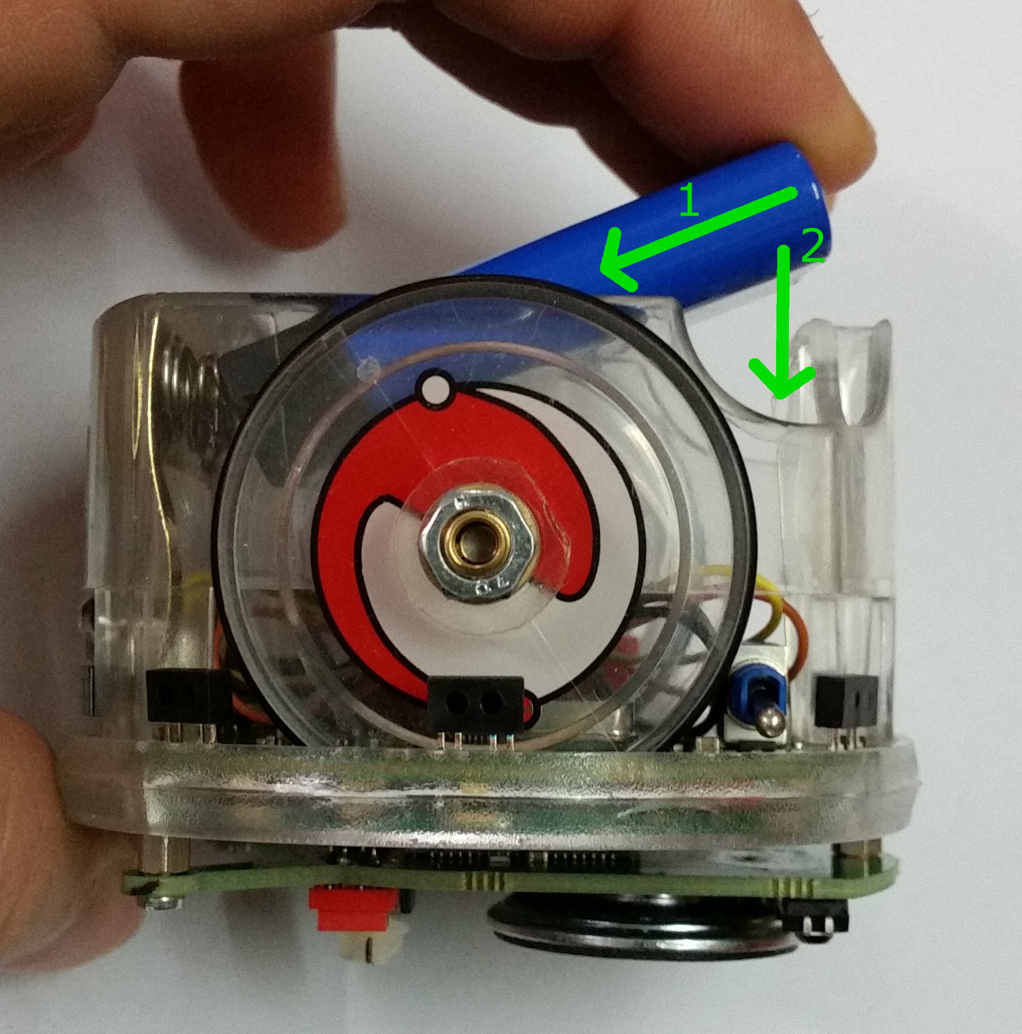
You should be careful when inserting and removing the battery of the e-puck in the robot or in the charger. Otherwise in the long run your battery will eventually lose its front isolator (plastic of cardboard), causing a possible short circuit. If you are already in this situation, you could try placing some isolation tape on the battery, as illustrated in the following figure. The correct procedure to insert and remove the batteries can be found in the following document Change-batteries.pdf. Basically you need to fully push in the battery compressing the springs before tilting the battery in the final position.
Bluetooth and MacBook
Some users experienced problems in connecting to the robot via Bluetooth using MacBook; using an usb BT dongle solved the problem most of the time. Some users instead experienced distance problems with the internal BT chip of the MacBook, that is the robot should be kept within 1.5 meters otherwise the connection is lost/slows down.
Memory protection
The dsPIC processor has the possibility to protect the program memory at various levels through the configuration bits; in principle these protections can be eliminated erasing completely the memory, anyway in some cases it was reported that this procedure fails, leading to a situation in which the "memory protection" still blocks and the robot cannot be programmed anymore. Thus it is advisable to avoid playing with code protection unless strictly necessary.
In principle the procedure to reset the configuration bits eliminating the protection is:
- Open the MPLAB project and connect the programming cable to the robot
- Select "Programmer => Select Programmer => MPLAB ICD3"
- Select "Programmer => Settings": in the "Program Memory" tab select "Manually select memories and ranges" and check all options, click also on full program memory range
- In the "Power" tab set the voltage to 5.5 V and check the option "Power target circuit from MPLAB ICD 3"
- Select "Programmer => Erase Flash Device"; erase should give no errors
- Power cycle the robot (unplug and plug again the programming cable); now the configuration bits are reset and program memory is cleared completely; it's possible to upload a new program selecting "Programmer => Program"
Note that this procedure works only with the ICD3 that is capable of supplying 5V to the processor.
Proximity noise
It was noticed that the proximity 0 and proximity 7 are subject to noise, in particular the value returned from these two sensors can vary up to 30 (the variation of the others is in the range of 2-3). This noise is coming from the camera clock, thus as a workaround the camera can be turned off if this noise causes problems.
ICD2 programmer
The Microchip ICD2 programmer P/N 10-00319 isn't supported on 64-bit OS.
Upload failed
If the robot was programmed with a firmware in which the Bluetooth is used to write continuously data to the computer, then you can experience problems in uploading a new firmware to the robot. To solve the problem you should try resetting the robot continuously during the connection to the robot when you are uploading a new firmware, basically you should reset the robot (press and release the button continuously) until the connection led turn on, then stop resetting; with a bit of luck you should be able to upload it.
Speed precision at very low speed
The e-puck motors are step motors. To save energy, the motor phases/steps at low speed are not energized all the time but just partially. This might affect the speed precision at speed below 200. If one has specific needs at that low speed and want the single steps to be more energetic, then the TRESHV and MAXV constants in the file \motor_led\advance_one_timer\e_motors.c within the e-puck library need to be adapted (decrease their value). Alternatively the power save feature can be completely disabled by commenting the POWERSAVE constant.
Mail archive
You can have a look at a mail archive (February 2007 - December 2016) regarding the e-puck robot from the following link https://www.mail-archive.com/e-puck-user@gna.org/index.html. In this archive you can find problems encountered by users and related solutions.
Bluetooth slowdown in Ubuntu
If you experience a slowdown using the Bluetooth in Ubuntu try removing the package modemmanager with the following command: sudo apt-get remove modemmanager
Links
http://www.e-puck.org/
https://www.cyberbotics.com/doc/guide/epuck
http://mobots.epfl.ch/e-puck.html
https://github.com/gctronic/e-puck-library
http://en.wikipedia.org/wiki/E-puck_mobile_robot