Elisa
|
The Elisa robot is no more produced. It's subsituted by Elisa-3, its more powerful successor! |
1 Overview
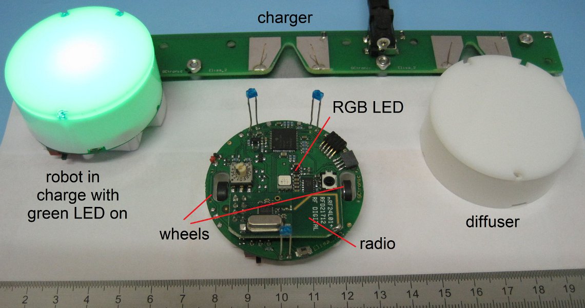
Elisa it's a small size robot with 5 cm of diamater, capable of moving also vertically thanks to its magnetic wheels. It includes:
- pic microcontroller (PIC24FJ64GA104)
- RGB led
- IRs emitters
- accelerometer
- RF radio for communication
- IR receiver
- DC motors
- diffuser
The robot is equipped with two batteries for a duration of up to 4 hours, about 2 hours at normal usage (motors run continuously, IRs and RGB leds turned on).
2 Getting started
2.1 1. Install the radio base-station driver
The base-station requires a driver in order to be correctly recognized, the driver is contained in the nRFgo-Studio utility (direct link for version 1.21.2 32bits and 64bits); once the utility is installed the radio will be automatically recognized.
2.2 2. Software
The Elisa robot has to be charged with either the official released firmware or with a custom firmware; pay attention that the custom firmware must configure the radio in the same way as the official firmware otherwise the communication with the base-station will not work. For more information and source code refer to the Elisa software section.
2.3 3. Demo
Once the radio is connected to the pc through usb and the robot is turned on, it's possible to execute a demo; this demo continuously sends new RGB and motors values to the robots. If all is working well the robot should turn on all the three RGB leds, or one of them depending on the robot address, in increasing level of intensitiy. For more information and source code refer to PC-side software section.
3 Communication
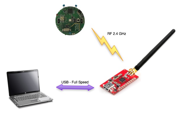
The radio base-station is connected to the PC through USB and transfers data to and from the robot wirelessly. In the same way the radio chip (nRF24L01+) mounted on the robot communicates through SPI with the microcontroller and transfers data to and from the PC wirelessly.
3.1 Packet format - PC to robot
The 7 bytes payload packet format is shown below:
| Command | Red led | Blue led | Green led | IR + Flags | Right motor | Left motor |
- Command: 0x27 = change state; 0x28 = goto bootloader (base-station)
- Red, Blue, Green leds: values from 0 (OFF) to 100 (ON max power)
- IR + flags:
- first two bits are dedicated to the IRs:
- 0x00 => all IRs off
- 0x01 => back IR on
- 0x02 => front IRs on
- 0x03 => all IRs on
- third bit is reserved for enabling/disablng IR remote control (0=>diabled, 1=>enabled)
- fourth bit is reserved for sleep (1 => go to sleep for 1 minute)
- first two bits are dedicated to the IRs:
- Right, Left motors: speed (in percentage); MSBit indicate direction: 1=forward, 0=backward; values from 0 to 100
Once the robot receives a new packet it returns its battery level to the base-station (one byte ack payload).
Both the packet format and the content of the feedback returned by the robot can be easily modified in the software.
4 Software
4.1 Elisa
The project is built with Microchip MPLAB IDE; the code to configure the radio is in "nrf.c"
The project source can be downloaded from Elisa firmware.
Selector position:
- 0: no controller activated (free running)
- 2: speed controller activated
4.2 Base-station
The project is built with Keil uVision for 8051 processor and then you'll need another tool for flashing a custom firmware to the radio base-station, that is the nRFgo-Studio. The source can be downloaded from base-station firmware.
In order to build the project you need the nRFgo SDK; once installed, you should find the SDK environment under C:\Nordic Semiconductor\nRFgo SDK 2.2.0.270.
The ptx example you can find in the directory C:\Nordic Semiconductor\nRFgo SDK 2.2.0.270\source_code\projects\nrfgo_sdk\enhanced_shockburst_examples was taken as the starting point for the base-station firmware. To build the projcet you need to put the firmware project directory within the C:\Nordic Semiconductor\nRFgo SDK 2.2.0.270\source_code\projects\nrfgo_sdk\enhanced_shockburst_examples directory to satisfy the references and then you can simply open the uVision project file enhanced_shockburst_ptx_nrf24lu1p.uvproj you find under \base-station\Keil\nRF24lu1p.
4.2.1 Bootloader
The base-station firmware contains a bootloader that can be used to update the functionalities of the module; in order to upload a new firmware follow these steps:
- plug the base-station to the pc through the usb; it will be recognized as a WinUSB device
- download the application goto-bootloader and run it; once executed you should see a message saying that the bootloader is entered
- now start the nRFgo Studio utility; on the left side you should find the base-station module recognized as a bootloader device, select it; on the right side you should be able to select your firmware and click Program; after a few seconds you should receive a message saying the upload was successfull
- once the upload is finished you need to unplug and plug again the usb cable (power-off and on) in order to enter your main program
.
4.3 PC side
4.3.1 Windows
The project is built with Code::Blocks (mingw) and sends data to 100 robots address 3010 to 3110) printing statistical information at the end of the transmission; in this demo it's suppposed that the robots return only one byte as response/ack payload.
The project requires libusb-1.0 since it is used to communicate with the radio base-station: libusb_2011.07.06.7z.
The source can be downloaded from windows demo.
Execution:
- install the driver contained in the nRFgo Studio tool if not already done; this let the base-station be recognized as a WinUSB device (bootloader), independently of whether the libusb library is installed or not
- once the driver is installed, the pre-compiled "exe" (under \bin\Debug dir) should run without problems
Compilation-windows:
- within the libusb-1.0 package you'll find the header "libusb.h" (under /include/libusb-1.0/) and the library "libusb-1.0.a" (in this case under /MinGW32/static/ since we use MinGW) that should be copied or referenced in the compiler headers/libraries
- add the linker flag "-lusb-1.0" in the project in order to build successfully (the Code::Blocks project has already set it)
4.3.2 Linux
The linux pc-side application "main_linux.c" send data to four robots and print the related battery level; in this demo it's suppposed that the robot returns only one byte as response/ack payload.
The libusb-1.0 library required for compilation can be downloaded from libusb-1.0.27.tar.bz2; alternatively you can simply type sudo apt-get install libusb-1.0 depending on your system.
The souce code can be downloaded from linux demo.
Compilation: gcc -o main_linux main_linux.c -lusb-1.0
Execution: sudo ./main_linux